 Collapsible soils in Argentina: experiences and case histories
Abstract
Argentinean loessial soils are the main deposits of this kind of soil in South America, and cover an area of more than 600,000 km2. They are eolic soils that can preserve their original structure generated when they were deposited (primary loess) or being transported or altered in place (secondary loess or loessoid). Recent deposits are mainly primary, ML and CL-ML, whereas the older ones are similar to other unsaturated clayed and silty soils, CL and CH. Geotechnical behavior varies from collapsing soils, for primary loess, to overconsolidated by desiccation for the secondary loessoid deposits. Advances have been made in the knowledge of the cementation processes, the dielectric properties and the mechanical variations with different levels of strains, in the use of new nondestructive methods, in-situ tests and spatial variations of the most significant parameters. It has been progressed in the modeling of foundations and different infiltration processes. The engineering design is conditioned by the type of collapsibility. The criteria used in constructions try to annul the entrance of water into the ground; to eliminate the collapsibility by means of the improvement of its unstable structure or to avoid using direct foundations. In hydraulic works predominates the use of the hydro-compaction combined with methods to accelerate the collapse. Loessic soils are apt for using in embankments and fillings, because compaction destroys their macroporous structure and they behave like other types of silty soils. In order to clarify the engineering problems and its solution two history cases are explained.
Keywords:
Collapsing soils; Foundations; Unsaturated soils
1. Introduction
Loess soils are predominantly silty soils whose name is indicative of the state of their internal structure. They were first studied in Germany in formations of the Rhine basin, where their name originated. This word has the same root as loose in English and means loose. Although there has been some controversy regarding their genesis, it is accepted that they are soils formed by wind action (primary loess) that can be retransported and redeposited by other means (secondary loess or loessoids).
In South America, there are several loessic or loessoid soils from the Upper Quaternary, genetically related by five types of eolian silt transport and sedimentation (Iriondo, 1997). Of these, the Pampean and Chaco types affect Argentina. They have been generically classified under the Pampean or Pampian Formation, although this name is sometimes restricted to older Cenozoic deposits.
In the field of engineering, the presence of these soils in Argentina was recognized in the 1930s, and they are already mentioned in the classic book by Scheidig (1934). However, clarification of ideas about their behavior occurred several decades later (Bolognesi & Moretto, 1957; Reginatto & Ferrero, 1973; Bolognesi, 1975). In the central area, loess constitutes the main regional soil and for this reason there are numerous publications (Moll, 1975; Moll et al., 1988; Moll & Rocca, 1991). The main geotechnical characteristic is its collapsibility, or the metastable state of its internal structure, which can be destroyed by changes in moisture content or tension. As a result, sudden volumetric changes occur that can affect structures unable to withstand significant distortions and differential settlements.
2. Characterization of loess soils in Argentina
2.1 Location
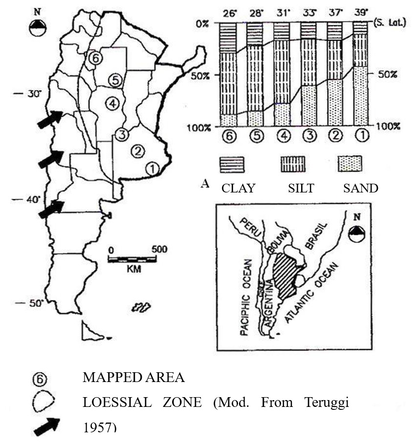
The loess-occupied area extends across the plains located from 23o to 38o S, covering more than 600,000 km2 (Figure 1). To the west, it is contained by several mountain ranges that occupy a strip extending north-south across Argentina. A subdivision between the Pampean loess (south of 30o S) and the subtropical Chaco loess (north of 30o S) has recently been proposed. Other loess deposits occur in mountain valleys and high-altitude plains in the west of the country. In neighboring countries, they have been reported in southern Brazil, Uruguay, and the Paraguayan Chaco.

2.2 Main properties
The characteristics of loess deposits depend on the distance from the particle source region. The transect in Figure 2 shows the spatial variation in particle size from the Pampas to the Chaco. Sandy loess is characteristic of the southern Pampas, while silty clays dominate in the Chaco.

2.2.1 Properties of ancient loess
Analyzing the properties of engineering importance, some traces of geological history can be observed. The deposits of the Pampean Formation date back to the Pleistocene and endured the consequences of the last glaciations. Successive sea level fluctuations were significant, reaching a decrease from the current elevation of approximately 110 m. The most significant effect was overconsolidation due to desiccation as the level dropped. These formations have been extensively studied by Bolognesi, Moretto, and collaborators at the University of Buenos Aires.
The deposits have clayey soils of fluvial origin with abundant montmorillonite, kaolinite, and quartz at their bases (Zone II of Bolognesi, 1975), on which loess with abundant illite and plagioclase have been deposited (Zone I). In a generalized profile near the Paraná River (elevation 0), three subzones can be distinguished in Zone I:
-
Relatively scarce, variable volcanic glass. From the surface to elevation +10.00. With very few exceptions, the soils are clays (CL or CH).
-
Abundant volcanic glass. From elevation +10.00 to elevation -5.00. The predominant soil is ML, which also has calcareous cementation and a structure with abundant cavities and pores.
-
Scarce volcanic glass, except in isolated horizons. Plagioclase is more abundant than in a). From elevation -5.00 to elevation -10.00. Between -5.00 and -8.00, CL clays predominate. Between -8.00 and -10.00, the soil has the same characteristics as subzone b) and constitutes the cinnitic silt layer that separates zones I and II.
Table 1 summarizes the main average index properties of these strata.
2.2.2 Properties of recent loess
Recent deposits are those that constitute loess materials sensu stricto and have as their main property their instability in the face of changes in humidity, causing the structure to collapse. They have been specifically studied at the Geotechnical Laboratory of the National University of Córdoba. There are nodules and microcrystals of insoluble calcium carbonate within the mass (less than 8%), formed by processes of wetting and drying cycles due to the capillary rise of bicarbonate, followed by crystallization (Rinaldi et al., 1998). Table 2 presents some of their most characteristic values.
The particle size distribution consists of sand (5 to 15%), silt (40 to 60%), clay particles (20 to 35%). Meanwhile, the liquid limit varies between 22% and 30%, and the plastic limit between 16% and 20%. Therefore, according to the Unified Classification, they are classified as ML or CL-ML soils.
The dry unit weight of these soils is generally low, ranging between 11 and 14 kN/m3, while the natural moisture content ranges between 8% and 25%. The specific gravity is 2.65 g/cm3. The corresponding porosity ranges around 0.5. The pore size distribution involves submicroscopic voids of 5 to 25% (in terms of void volume) and voids of 1 to 20 microns (30 to 80%).
2.3 Behavior
2.3.1 The role of moisture content in primary loess
Water plays a very important role in the formation and subsequent behavior of loess (Rinaldi et al., 1998). As moisture content decreases, fine particles move toward the meniscus, the ionic concentration in the pore fluids increases, the thickness of bilayer decreases, and Van der Walls forces of attraction prevail over the repulsion forces of the bilayer. The simultaneous increase in suction also increases strength, which is more effective between clay particles in bridges and buttresses than in the menisci between coarse particles. The combined effect of these processes gives loess high cohesive strength, allowing vertical shear and the ability to withstand significant loads.
Increasing moisture content reverses these processes: soluble salts hydrate and weaken, and the ionic concentration in the fluid continues to decrease with increasing moisture content. As the ion concentration decreases, the double layer that forms around the particles increases. The shear stiffness and strength of clay formations decrease as the hydrated layer increases. Repulsive forces become dominant, and clay particles disperse. Also, suction gradually decreases as the degree of saturation increases.
Eventually, the structure weakens and collapses even before reaching saturation. Very little external load is required to achieve final collapse, and sometimes the weight of the soil mass itself is sufficient. Collapsibility is also influenced by the characteristics of the percolating fluid. These interact chemically with the internal bonds, which can accelerate or delay their destruction. Waters with high pH tend to be more harmful (Reginatto & Ferrero, 1973).
2.3.2 The collapsibility of primary loess
Collapsibility can be studied using oedometer tests. The compressibility curve under saturated conditions shows a threshold called the initial collapse pressure or saturated yield pressure (σFSAT), beyond which significant changes occur in the soil's structural bonds (Figure 3).

The relationship between saturated yield pressure, a soil property, and the in situ stress state (σ0), leads to the division into two types of soils:
-
Potentially collapsible loess: when the capping pressure is lower than the yield pressure after wetting, σ0 < σF.SAT. Stability will depend on the magnitude of an external load on the soil.
-
Self-collapsible loess: when the capping pressure is greater than the saturated yield pressure. σ0 > σF.SAT. In this case, the soil mass will collapse spontaneously without the need for external loading.
When these relationships are plotted at depth, collapsibility profiles are generated, in which the in-situ stress (σ0 + Δσ) is compared with the saturated yield pressure (σF.SAT), (Figure 4). During a process of increasing humidity, collapse settlements will occur in those sectors where the acting pressure is greater than the yield pressure. These profiles make it possible to define the foundation elevation of deep foundations and the sectors where negative friction processes are likely. The thickness of these self-collapsing layers depends on regional characteristics. They are generally superficial layers, but they can also be intermediate layers, for example, 5.0 to 7.0 meters deep.

2.3.3 Shear strength
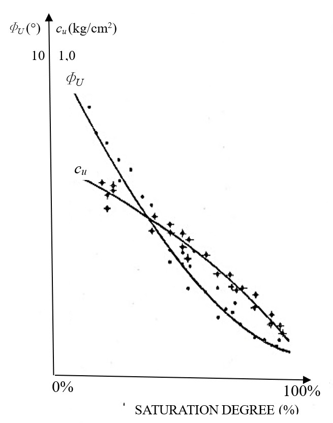
The average shear strength varies substantially with the degree of saturation, due to the collapse of the internal structure. Figure 5 shows the variation in undrained shear parameters obtained from triaxial tests performed at different degrees of saturation. As with compressibility, suction is an important variable. In general, cohesion is the parameter with the greatest variation, but not the angle of internal friction. In drained triaxial tests on saturated samples, the average angle of internal friction is around 24°. In plate-load tests, upon saturation, sharp decreases are observed, with settlement values 10 to 20 times those corresponding to naturally humid conditions (Nuñez et al., 1970).

2.3.4 Hydraulic conductivity
Loess soils exhibit unique hydraulic conductivity anisotropy, with the vertical permeability coefficient (kv) greater than the horizontal permeability coefficient (kh). The upper levels of clayey silts structurally exhibit a network of visible fissures and microfissures. In their natural state, these soils are generally undersaturated, with the intervention of three phases. The model used to interpret various infiltration tests performed on these loess soils analyzes the solution to the continuity equation of one-dimensional unsaturated flow (Terzariol et al., 2003). As a transient flow, and in unsaturated soils, the permeability (kΨ ) of the medium depends on matric suction (s), which is determined by volumetric moisture content (θ).
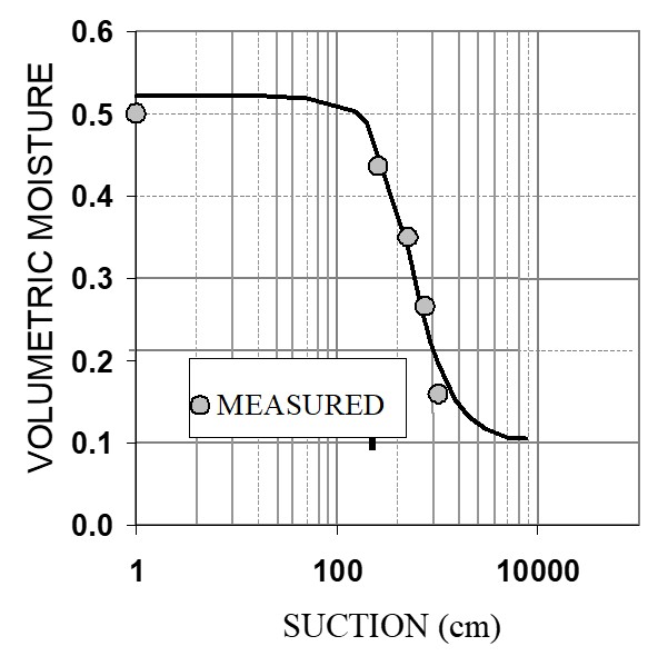
To apply the calculation algorithm, knowledge of the relationship between volumetric soil moisture and matric suction, the so-called soil-water characteristic curves, is required. Figure 6 shows one of these curves obtained from a loess soil in Córdoba (Zeballos et al., 2002).

2.3.5 Wave propagation velocity
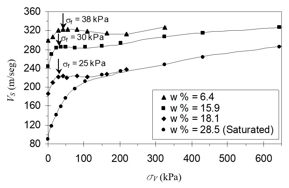
The velocity of shear wave propagation is fundamentally linked to the stiffness of the soil structure, density, and contact stresses between particles. Figure 7 shows how the velocity of shear waves increases with pressure and decreases with moisture content. The curves do not follow hyperbolic behavior as in uncemented soils, of the Vs = k (σ)α type. Instead, they show a break coinciding with the collapse pressure. This break is less pronounced in the case of the saturated sample.

Shear wave propagation velocity measured during an oedometer test for samples at different moisture contents. The yield stress is indicated in the curves (Rinaldi et al., 2001).
From various downhole tests conducted in natural moisture, a law of average variation of the shear wave velocity (VS) as a function of geostatic confining pressures (σo) was determined (Rinaldi et al., 1998).
Where σo is expressed in kPa and Vs in m/s.
2.3.6 Electrical conductivity
In the case of semi-saturated soils, Rinaldi & Cuestas (2002) determined the following expression for the Resistivity Index Fs:
where σw and σs are the conductivities of the fluid and the soil sample; a and m are constants and the parameter p is a function of the dry unit weight γd and is determined by:
3. Recommendations for characterization
3.1 Field tests
Traditional in-situ tests such as the SPT have serious limitations, as the strength and stiffness of primary loess soils are strongly dependent on the moisture content at which the test is performed, and they cannot measure or evaluate the main geotechnical characteristics of these soils (Reginatto, 1971).
In the 1990s, specific in-situ tests (Figure 8) were developed to determine collapsibility. Some of them have been applied to collapsible loess (Terzariol & Abbona, 1999). This allows direct quantification of behavior, with the advantages of in-situ methods over laboratory methods, but with the disadvantage of the costs involved. In general, they are reserved for cases where it is not possible to preserve the structure of the samples for laboratory testing.

There have also been attempts to use indirect methods, such as geophysical methods, using both mechanical waves and GPR (Rinaldi et al., 1998).
3.2 Laboratory tests
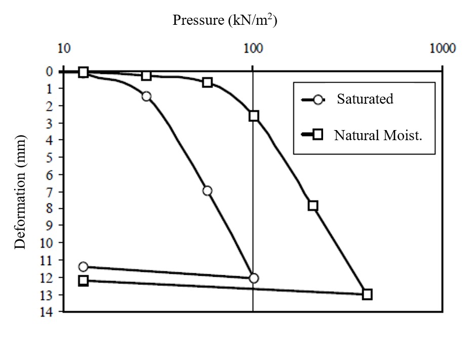
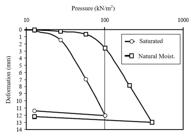
The characterization of loess collapse has been carried out for several decades using oedometric tests on undisturbed samples. The use of index properties produces equivocal results (Redolfi et al. 1986). The classic test is the double oedometric test, performed on twin samples under natural and saturated moisture conditions (Figure 9). In Argentine practice, the oedometric test on a single specimen, performed in a saturated state, is primarily used.
The differentiation between the different types of behavior, self-collapsing and potentially collapsing, can be made by using deformational or tensional criteria. In Argentine practice, the latter predominates (Rocca et al., 1992; Redolfi & Oteo Mazo, 1994).
4. Soil performance for design and construction purposes
4.1 Preconsolidated deposits of ancient loess.
These formations, 30 to 45 m thick, are partially saturated above the water table and saturated below it. They have been generated by various cycles of sea level rise and fall during glaciations. This preconsolidation effect due to desiccation is reduced with depth. (Nuñez, 1975). The foundations of the structures are calculated at failure, using the parameters cu and Φu obtained from undrained triaxial tests.
In preconsolidated silts and clays, it is possible to execute deep excavations with vertical cuts and small temporary support structures. The study of some failures indicates that the soil responds to established theories for cohesive soils, assuming cracking of about half the depth of the cut. For typical formations, the critical height is of the order of 20 meters.
4.2 Recent loess deposits
4.2.1 Shallow foundations of architectural buildings
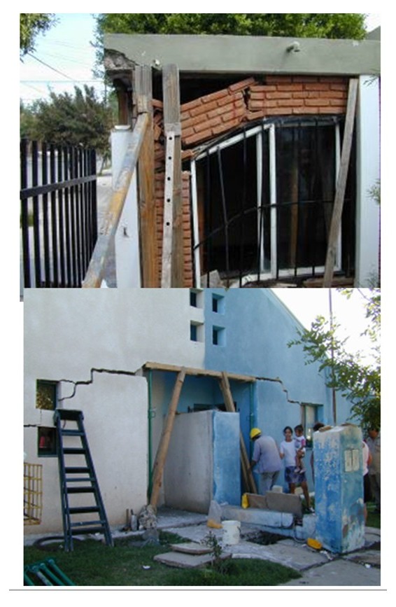
When soils are self-collapsing, no structure founded on them performs satisfactorily. Figure 10 shows the damage caused to shallow-founded houses when water enters the soil.

Various approaches can be taken to construct direct foundations in these types of formations:
-
Reduce the likelihood of collapse by altering or improving the soil. This is achieved by reducing porosity (hydraulic compaction, dynamic compaction, blasting, pile driving, etc.), or by strengthening the bonds between particles (silicatization, firing, jet grouting, etc.).
-
Minimize the conditions that favor soil collapse. This can be achieved by adopting measures to prevent soil wetting (lining of buried pipes, perimeter sidewalks, properly designed storm drains, etc.) or by reducing the pressure acting on the ground.
-
Mitigate the effects of collapse on structures founded on these soils. This involves adopting structural measures (chaining foundations and walls, using structural partitions, isostatic structures, etc.) or reducing the lithostatic load through excavation relief.
The magnitude of the collapse of a collapsible soil stratum, with thickness Ht, wich is moistened in all it thicknesses, can be defined as:
where:
Ht = H1+H2+... = Hj+...Hn
Hj = Stratum thickness j
Wcol.j = Stratum j collapse
δcol.J = Relative collapse of the stratum j under σzj stress.
σzJ = Total stress in stratum j.
dcol the relative collapse, in laboratory, can be defined as:
Where:
hHN = Height of the specimen natural moisture content (before wetting), under any stress σ.
hSAT = Height of the saturated specimen (after the collapse) under a stress σ.
h1 = Height of the specimen at natural moisture under an axial stress equal its self-weight.
In many localities, the rise in the water table brings with it significant settlement of buildings due to collapse, and when the water table drops (or is lowered by pumping), settlements are generated due to variations in effective stresses (Zeballos et al, 1999).
4.2.2 Pile foundations (vertical loads)
Given the background of loessic soils, there is a tendency to base structures on piles. This is done to avoid settlements due to collapse of the soil mass. However, there are numerous cases where this type of solution has not been satisfactory (Abbona et al., 1990).
The most important study on this topic has been conducted considering the variations in the interface between the loessic soil and the pile (Redolfi & Oteo Mazo, 1992).
Experience shows that even structures founded on piles have suffered significant damage due to the collapse of the surrounding soil. This problem is associated with decreased frictional capacity, with the resulting load transfer to the pile base and the phenomenon of negative friction, due to a widespread collapse of self-collapsing soil strata.
The most likely scenario for a pile embedded in a collapsible soil is shown in Figure 11 (Redolfi & Oteo Mazo, 1992). It shows that as the soil around the pile becomes wet, its frictional capacity decreases, and the external load begins to be transmitted to the lower part of the pile.

This load transfer is associated with deformation of the underlying soil and settlement of the pile. If wetting becomes widespread and the soil self-collapses, this change in relative deformations generates reloading of the pile, with a corresponding increase in settlement.
In general, piles have minimum dimensions controlled by construction processes, which are inconsistent with actual load requirements. That is, piles with small external loads are oversized, especially in terms of their frictional capacity, while piles with high external loads have dimensions more in line with their structural needs and, consequently, greater compatibility between frictional and tip capacities.
This situation means that, in the case of localized wetting, low-load structures founded on piles are seriously affected by lateral soil wetting, since they must undergo significant settlements to transmit the load to the lower strata. On the other hand, structures with greater loads, faced with the same situation, may exhibit less compromised behavior because the load is already being carried by the pile base, and the increase in load may be negligible in terms of settlement. In either case, the general wetting of a stratum, with the appearance of negative friction phenomena, leads to significant structural problems.
4.2.3 Pile foundations (horizontal loads)
In many cases, piles are also subjected to significant lateral loads. Horizontal loads can be caused by wind forces, earth pressures, earthquakes, etc. The behavior of piles subjected to horizontal loads in loessic soils is of interest because these soils are the predominant ones in the central-western region of Argentina.
In the particular case of the city of Córdoba, these soils occupy the superior layers (15 to 20m), and the city are included in the Argentine Seismic Zonification as a medium seismic zone, for this reason foundations must be verified under lateral loads. To verify foundations under these conditions, either conventional elastic formulations (Equation 6) or elastoplastic formulations (p-y curves) are used.
Where z is depth below surface and D is the pile diameter
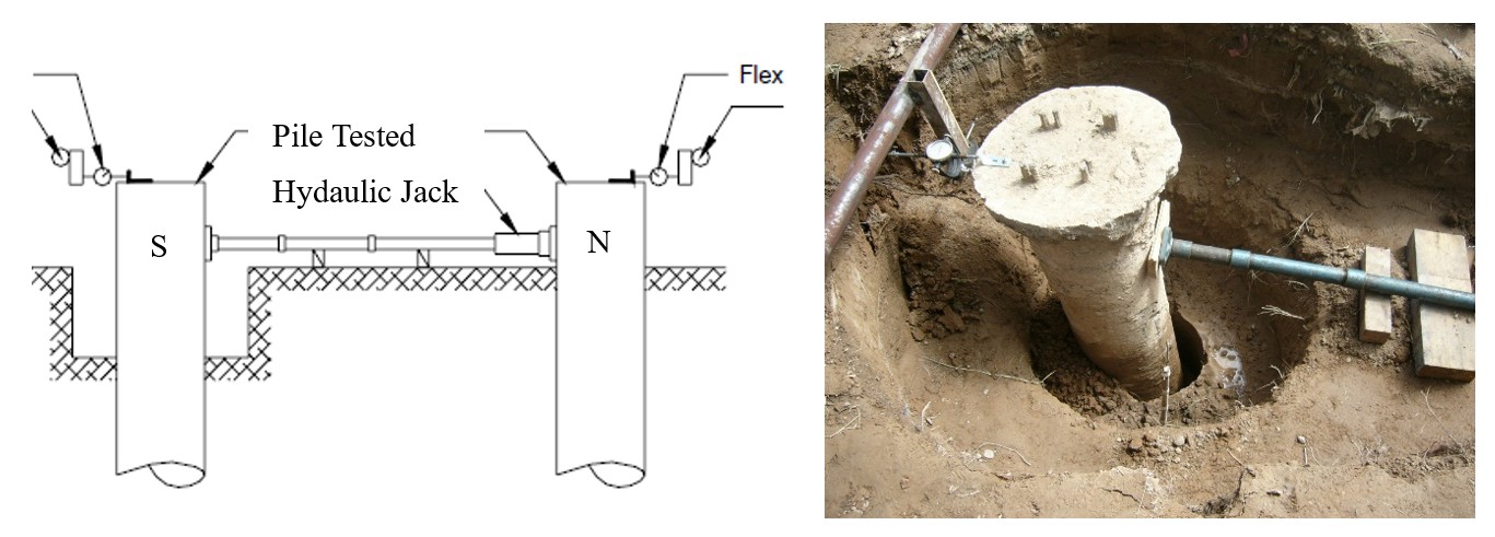
Therefore, many pile tests under lateral loads (Terzariol et al., 2006) over piles in saturated soil were performed to obtain the design parameters. A schematic of one of these tests and a photo of the final displacement are shown in Figure 12.
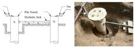
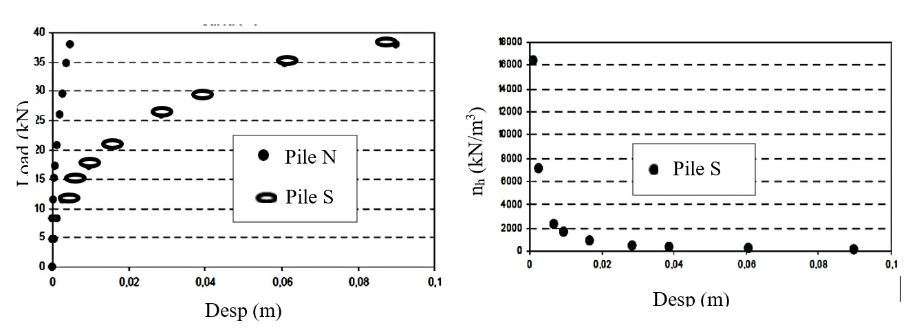
Figure 13 shows a typical lateral load vs displacement curve and the degradation of nh.

In order to take account of that degradation can be used other Equation 7 to define the variation of Kh with the soil condition and the depth analyzed.
Table 3 shows the values of α and β as function of the relative displacement.
4.2.4 Foundations for pipelines, canals, dams, and other hydraulic works
This type of work is particularly dangerous because it transports or stores the agent that causes soil collapse, i.e., water.
On linear surfaces, various types of surface erosion processes occur that affect engineering works, from drains to canals.
In the case of canals or linear works, soil presaturation by flooding can be used. The specific stratigraphic conditions along the route, such as layers of different permeability, etc., must be taken into account to meet the hydro compaction design requirements (Nuñez, 1975).
In the province of Córdoba, there are precedents of canals constructed in this type of soil (Moll et al., 1979). Soil replacement techniques (excavation and compaction with the addition of cementitious agents) were used with relatively good results. The faults were detected by the formation of tube-like erosions below the channel related to the lack of control of the surface flow of water external to it.
Structures built along the canal must be designed so that their foundations are not affected, or requirements must be met to mitigate the problem. For bridges, the use of piles and pre-saturation beneath the approach embankments is common.
Structures built along the canal must be designed so that their foundations are not affected, or requirements must be met to mitigate the problem. For bridges, the use of piles and pre-saturation beneath the approach embankments is common.
In the case of conduits and related works, the structural behavior of the conduits must be added to the observations in the previous section for linear works. Some of them lack resistance to the tensile forces generated at the corners of the change of direction, valve chambers, etc. For this reason, fixed points capable of resisting large lateral forces are established, such as large-diameter piles, or, in certain cases, the replacement or treatment of collapsible soil is considered.
In the city of Córdoba, water supply and stormwater drainage conduits have recently been built in areas affected by collapsible soils. The foundation solutions have included the use of piles in the chambers and junction areas, as well as the placement of highly permeable soil as a drain, surrounding the pipeline within a casing of impermeable geotextile material, with control chambers that allow for early detection of leaks before they affect the natural soil.
For storage structures (cisterns, tanks, etc.), deep foundations have been used successfully, combined with measures that allow monitoring of the structure's condition throughout its useful life.
In the case of reservoir dams and related structures, when they are founded on loessic soil, it is necessary to prevent the settlements that will occur when the reservoir is filled. If the soil thickness is relatively small, the most economical option is to remove it and replace it with compacted soil. If the thickness is considerable, hydro compaction of the foundation is required. The main challenge will be predicting settlements and mobilizing shear strength for dam design.
In Argentina, there are experiences dating back to the 1960s when the Hondo River dam was built, located in the Chaco loessic region, where systematic research was carried out on water supply, application periods, studies of compressibility characteristics and shear strength (Moretto et al., 1963).
4.2.5 Erosion control in loessic soils
Loess soils are characterized by being highly friable, that is, poorly resistant to water erosion. This is inherent to the characteristics of the internal macroporous structure, the columnar disjunction generated by the deep roots of grasses, and the mechanical properties dominated by silts with little cohesion.
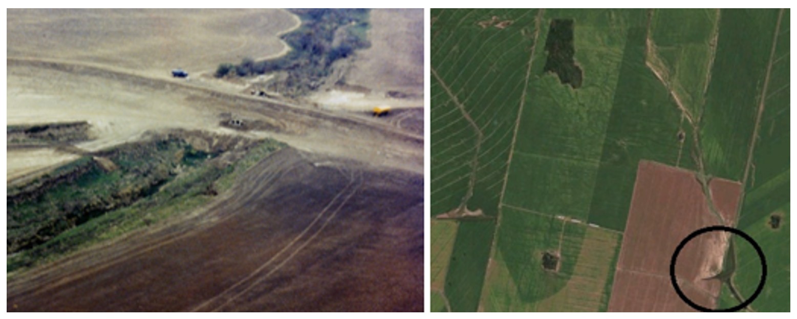
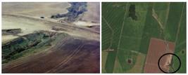
The evolution of loess relief is extensively discussed in the international literature. Gullying processes can have various origins, both through linear erosion and the collapse of intense pipe formation that has led to the formation of tunnels. Once an incipient gully forms, flow is channeled through it, and over time, it becomes a sporadic watercourse. In Figure 14 it can see a gully in formation.

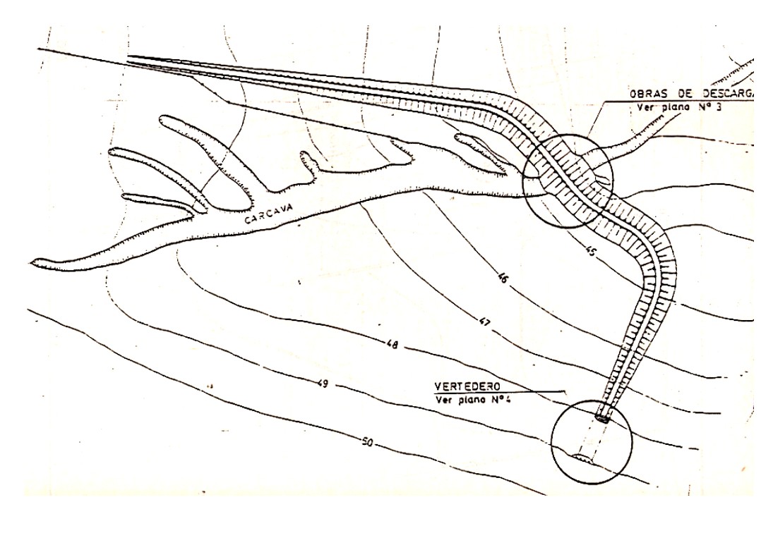
To prevent erosion problems and improve overall agricultural conditions, a Soil Conservation Consortiums was established in the mid-1980s. Among the solutions proposed and implemented were both cultivation practices and those emphasizing water management. These includes cultivation following contour lines, terraces, silted channels, and runoff retardation works. Several retention dams were built.
These dams consist of a homogeneous, curved embankment, with slopes of 1v:3h on both sides. The maximum height is approximately 12 m. To control runoff, pipes were placed, embedded in plastic cement soil at middle height, to allow the sedimentation of fine particles. Figure 15 shows an example of that kind of solutions. Also Figure 16 shows the dam during construction and the gully totally filled and stabilized 10 years after,

4.2.6 Loessic soils as a construction material
When loessic soils are used as a construction material, they lose their structure and behave like silty soils under unsaturated conditions. Their strength in terms of total pressures is a function of the degree of saturation (Nuñez, 1975).
Although the deformation modulus varies with humidity, it does not present problems of collapse.
When compacted, they exhibit good strength characteristics and low deformability. This makes them suitable for use in road embankments, fills, or for the construction of earth dams. One of the limitations is the salt content that can deflocculate the clayey fraction.
5. History cases
5.1. Damage to the los Molinos-Córdoba canal
5.1.1 Main description
During the 60´s and 70´s, the Córdoba Water Agency build a 60 km canal in order to provide water for Córdoba city and irrigation of its neighbor green belt.
The canal begins in a dam located over the Los Molinos River and border it to the East, and then takes the north direction to the San Jose de la Quintana town. Always to the north crosses the Anisacate river and take the south direction. After a few kilometers crosses the Nacional Route Nº 36 nearby the Xanaes river. In this point takes north-east direction to Córdoba´s Water Treatment Plant, through Rafael García town.
The canal has a curve shape (see Figure 17), and its revetement is plain concrete, with a few centimetres thickness. The canal follows the topographic contour, maintaining a safe hydraulic longitudinal acclivity.

This situation implies that intercepts the natural surface water flows along the entire canal route. For this reason, was necessary to construct water passages, canal bridges, siphons, guard little canals, side embankments, with different results in terms of its mission. Also, all the local routes cross the canal mean bridges (Terzariol, 2012).
5.1.2 Soil characterization along the canal
In general, there are collapsible soils (Terzariol, 2012), but in many zones it can be found sand layers and rocks.
The soil settlements produced in the neighbour of the canal, generate singularities like crack sor voids, in the surrounding farmlands. As a semi-arid region, the rainfall is torrential during the summer and is practically zero during the other seasons.
During the rainfall storms, in the absence of main water courses, the water flows as a big carpet affecting the entire area equally.
When the water carpet intercepts the singularities begin the erosion, originally in the surface generating retrogradation gullies that scout the soil to find a cemented layer that interrupt the mechanism. In other points, can be generate tubified erosion that flows under the highways, canals, routes, etc. That tubification has the local name of mallines. Figure 18 shows the singularities, and erosions, near the canal and the neighbour farmlands.

For a clearer description, the canal route was divided in two zones with different construction characteristics. Also, the second zone is divided in two sub-zones with different kind of damages.
-
Zone I (Between the beginning of the canal and the Route 36 crosses)
This section was the first constructed. The soil predominant are sandy silt and sand layers with little thickness, Ander it we can found massive rock, like granite or gneiss, and conglomerates like the Estancia Belgrano Group, conformed by rolling stones, gravel and sands in a silty-clayey cemented matrix.
It can be found the conglomerates near the Route 36 and the granites or gneiss near the beginning of the canal. Silts have low plasticity (IP ~ 4%), the moisture content is under 13% and upper 7%. According laboratory tests these soils are potentially collapsible. The blow account in the SPT test shows values under 10, in natural moisture content condition.
The sand layers have a grain size fine or medium with lenses of gravel. The sands has an average NSPT ~ 30 blows/30 cm. In this zone the canal don´t shows significant damages.
-
Zona II (Between the Route 36 crosses and the Water Treatment Plant)
Here the canal runs through silty aeolian soils. Its are soils with a low plasticity (2%<IP<6%), and lows values for the Atterberg limits (18%<wP<23% and 21%<wL<30%), in the Casagrande Chart its are ML or CL-ML. The voids ratio is near to 1, and the moisture content for a 100% saturation degree is 33%. The natural moisture content is under 11%. The water table is deep (more than 20 meters). Are very erodible soils generating desertification in the surrounding farmlands. The compacity is low (5<NSPT<10).
The moisture content near the damages in the canal was between 18% and 31%, or in other words, a degree of saturation between 60% and 90%. The moisture content is enough to produce soil collapse. The laboratory tests show potentially collapse soils and, in a few zones, there are self-weight collapse soils.
In this zone it can be found the major damages. In general, the most important damages are in the zones where the canal was constructed with lateral embankments or the excavation is very low.
In the construction of the canal there was involved 2 different kinds of Works. We can divide the canal length in 2 sub-zones.
-
Sub Zone II-a (between a few kilometres after the Roue 36 cross and the suburbs of Rafael Garcia town): Here the construction was developed as a simple excavation with no substitution or soil improvement. In this zone the damages occur suddenly without any previous signal. When a concrete slab crack suddenly the other slabs in the vicinity collapse.
-
Sub Zone II-b (between the suburban area of Rafael Garcia and the end of the canal in the suburbs of Cordoba city): Here the canal was constructed after a previous improvement of the natural soil. The methodology was made an excavation, improve the soil adding lime or cement and compact it in the previous hole. After these works the canal section was excavated and construct the slab of revetement. In this zone the cracks do not occur suddenly but progressive in the time. This situation allows a more efficient reparations in the damaged slabs.
5.1.3 Damage description and reparation works
The damages consist in cracks, fissurative patterns, slabs collapse, general settlements in the canal and in the surrounding area. The maximum displacement between slabs was about 30 to 50 cm and the general settlements reaches 1,00 to 1,50 meters.
Terzariol (2012), shows that the more elemental reparations were cover the canal with a plastic membrane and grow up the canal`s sides with little walls or sand bags. When the settlement was generalized it shall be necessary to demolish little bridges.
The settlement along the canal length is shown in Figure 19, also the figure shows the water level, and the borders of the canal.

The major reparation Works consists in refill the tubified erosion and constructs a concrete trench or walls, 4,00 meters depth. In many cases these reparations were satisfactory and not in other cases.
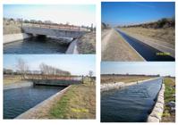
In Figure 20 it can be seeing a bridge after an before repairing works, and a general view of a canal section after and before the repairing works.
5.1.4 Analysis of the problematic involved
A simple description of the damage and the geotechnical profile fail to interpret its magnitude and distribution along the route. In order to do this, it is necessary to understand that the damage is caused by the action of water external to the canal, whose surface runoff, as stated, causes erosion or piping when it encounters peculiarities near the canal, generally caused by its construction and operation, coupled with the lack of surface water collection, which affects the structure.
As indicate, the most significant damage occurred in Zone II and, in particular, in Sub-Zone IIb. Figure 21 shows the supply basins along the canal and their relative influence on the canal's route.

Zone I have a small supply area, and the local soils are non-collapsible, even with outcropping rock layers. Therefore, damage is practically nonexistent and limited to specific problems that are easy to resolve.
Throughout Zone II, the soils found are potentially collapsible.
Sub-Zone IIa has a medium-sized supply basin, and due to the topography of the area, the canal runs through sections excavated in trenches or excavated from the surface, but with almost no embankment sections. The low water supply and the fact that, due to the topography, water tends not to intercept the canal (trench excavation) mean that the damage in the area is of medium intensity and located in short, well-differentiated sections. Finally, sub-zone IIb, for its part, is the one with the largest contribution area, and due to its very flat topography, the canal has areas with a semi-buried or embanked section with very few sections in which guard ditches and lower water passages have been planned.
The soils detected in Zone I are non-collapsible soils or rocky outcrops. This, combined with a limited area of surface water supply, explains the absence of significant damage regardless of the construction method used, as no soil improvement was carried out by concreting the canal lining directly over the excavation.
The soils detected in sub-Zone IIa are potentially collapsible, but with a limited watershed affecting it. This, combined with the local topography that minimizes the interception of this water with the drainage ditch, results in a manageable level of damage. In this zone, the construction method used, identical to that in Zone I, has resulted in localized damage within a short period of time, with fragile crack propagation in the lining slabs.
The soils in sub-Zone IIb are potentially collapsible, and the watershed is the largest in the project. The local topography, meanwhile, requires excavated sections that intercept surface water runoff without adequate catchment structures, resulting in widespread and significant damage. The construction method, which included soil replacement using limestone, has controlled the damage's spread to the lining and allowed for scheduled repairs.
5.2 Damage for self-collapse in an educational center
In year 2000, a school complex was built in the western suburbs of Córdoba, consisting of a kindergarten, a primary school, and a secondary school (Terzariol et al., 2009).
The soil study conducted for the school building project showed that the area has a thickness of over 30 meters of self-collapsing sandy loam soils.
Previous geotechnical data, summarized in collapsibility maps, indicate that the area has a settlement potential of approximately 45 cm if the first twelve meters are saturated.
The buildings were constructed using precast reinforced concrete columns (RCC), beams, and panels, simply supported or joined by welded inserts. Since there was no loamy foundation to support the foundations, the structures were supported by friction piles approximately 15 meters long. The complex's wastewater is discharged into the ground through a borehole at least 30 meters deep after being treated in a compact plant located on the same property as the buildings. The borehole was located near a sports court that serves as the central courtyard for the entire complex.
Throughout 2007 and 2008, movements began to be observed in the prefabricated structures, indicating some type of differential settlement. This caused the construction joints to open and damaged some installations, particularly the gas lines in the kindergarten. This situation led to the preventive closure of the kindergarten and the completion of a geotechnical and structural assessment prior to its reopening.
To study and interpret the phenomena that occurred, a series of experimental and theoretical actions were carried out. The experimental work included surface leveling and drilling in the area of influence. Based on the characterization of the affected profile and its comparison with the situation prior to the filtration process, sufficient information was available to use a numerical model to calculate the settlements produced by the advance of saturation (Terzariol et al., 2003). This model allowed comparisons between field results and those obtained in the simulation, validating its ability to explain the phenomena represented.
The surface topography surveyed confirmed the findings of the initial inspection, as seen in Figure 22. It shows maximum relative settlements between the perimeter and the center of the property, ranging from 40 to 50 cm. These are highest near the drainage borehole. The settlement contour lines show a remarkably symmetrical subsidence of the entire site toward the source of groundwater ingress.

5.2.1 Behavioral modelization
In the specific case of collapsible soils, volumetric change is commonly associated with changes in soil suction and the failure of cemented bonds. Because of this, it is necessary to combine infiltration and stress analysis, either coupled or uncoupled, to solve the problem.
The relative collapse model is an alternative for simplified analysis of the problem, and is especially applicable in cases where the soil undergoes continuous increases in moisture content.
For situations in which stress paths are more complex, developing, for example, variations in moisture content in alternating wetting and drying processes, elastoplastic constitutive models, such as the one proposed by Alonso et al. (1990), are applicable.
The relative collapse method is based on the identification of a collapse function. This function associates the observed settlements in the soil resulting from increases in the applied external pressure and soil moisture content. It allows the construction of a state surface in the space of total pressures (σ), moisture content (w), and the relative collapse settlement (δ). This relative collapse is expressed as:
Where, δi is the relative collapse occurring in element i of the geotechnical profile originally divided into n elements; σi,f and σi,o are the final and initial external pressures to which element i is subjected; α(w) and β(w) are functions dependent on soil moisture.
Finally, the settlement is calculated by summing, along the soil profile, the product of the relative collapse and the stratum height for which said collapse is considered applicable. Consequently, the total settlement (Δ) produced by relative collapses resulting from moisture changes in the geotechnical profile considered is calculated as:
where Δi is the settlement produced in element i; Hi is the thickness of the stratum.
The results of confined compression tests performed on undisturbed samples of clayey silts and sandy silts from the loessic formation of the city of Córdoba were used as a reference.
The set of tests identified an initial moisture content, which was considered a reference moisture content for the purpose of assessing settlements. The initial moisture content was set at 16.0%, yielding the relative vertical deformation curve (ε) as a function of the applied external pressure.
The results obtained show nonlinear behavior between the variables involved. Based on these responses, two distinct sectors can be identified. The first sector shows exponential growth in relative collapse. This condition remains constant up to a certain external pressure value, beyond which the collapses remain constant or tend to decrease slightly. For the first sector, the constants α and β were identified, considering the equations valid up to a mean external pressure of 100 kPa. The results obtained are represented in Figure 23.

In the exponential sector, the parameter β is approximately constant, equal to 1.10. The parameter α has been related to the change in moisture content relative to the reference moisture content. The quadratic relationship equation is as follows:
5.2.2 Analysis carried out
The modelization performed consists of evaluating the expected settlements resulting from the modification in the moisture content of the soil profile.
For this analysis, two distinct moisture states were considered. The initial scenario was characterized through studies conducted prior to construction. During these surveys, the affected soil type, dry unit weight, and natural moisture content were identified. The final scenario was characterized through the results of surveys conducted through investigational boreholes after the settlement phenomena were observed. On this occasion, the new moisture states of the profile were identified at different depths.
The following calculation assumptions were applied to develop the numerical analysis:
-
The observed settlements occur entirely as a result of a change in soil content between the initial and final scenarios.
-
These settlement processes occur over a sufficiently large area to be considered dominant in one-dimensional settlements. Consequently, the effects generated by shear stresses caused by differential settlements are of little importance.
-
The relative collapse equation has a maximum settlement value for states of applied vertical pressure equal to 100 kPa. For values higher than the one considered, it is assumed that the material produces a response similar to that obtained for the aforementioned value.
The modeling steps were as follows:
-
Identification of the variable indicative of the initial scenario, particularly the moisture content of the soil profile, and definition of the initial total pressures.
-
Definition of the moisture conditions observed in the boreholes located 5 and 30 meters from the infiltration zone. In each of these profiles, both the new value of the total pressure, modified by the variation in moisture content, and the increase in moisture content are assessed.
-
Based on this increase, relative to the reference moisture content, the coefficient α applied at each level of the profile considered is evaluated.
The moisture states considered, in the initial condition, as well as in the final state at the two indicated positions, are presented in Figure 24.

Relative collapse is defined based on the total external pressure acting on each level of the profile, as well as the variation in moisture content produced. These collapses are transformed into relative settlements, based on the height of impact at each level, and subsequently integrated for the entire profile considered.
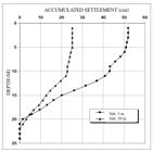
Figure 25 shows the accumulated settlements from the deepest point in the profile to the surface. Absolute settlements of around 0.50 meters are observed near the filtration point, while relative settlements between the boreholes are around 0.25 meters. Very good consistency is observed between the measured values and the numerical modeling results.
6. Conclusion
In conclusion, some final comments can be made.
-
A description of both primary and secondary loessic soils is presented, along with their origin and location in Argentina.
-
Collapsible loessic soils are described, analyzing their regional problems and, in particular, the structures built on them.
-
The most relevant geomechanical parameters for these soils, along with their order of magnitude and most common variations, are provided.
-
Recommendations are made regarding the most commonly used characterization methods in the field and their results.
-
An evaluation is carried out of the foundation systems most commonly used in Argentina and their results over more than 60 years of experience in their use.
-
The design methods for these foundations and the expected behaviors with them are presented.
-
Through two analyses of two local case histories related to foundation and construction problems on collapsible soils, evaluating the construction methodologies employed, the prediction methods commonly used, and the remediation methods used.
-
Finally, this presentation reflects the experiences of more than 50 years of studies and research carried out to date at the Geotechnical Laboratory of the Faculty of Exact, Physical, and Natural Sciences of the National University of Córdoba, Argentina.
List of symbols and abbreviations
a, m, p Conductivity constants
cu Undrained cohesion
eo Void ratio
h Height of laboratory specimen
hHN Height of the specimen natural moisture content (before wetting)
hSAT Height of the saturated specimen (after the collapse)
h1 Height of the specimen at natural moisture under an axial stress equal its self-weight
ks Saturated hydraulic conductivity of soil
k(v;h) Hydraulic conductivity of soil (vertical; horizontal)
kΨ Permeability as a function of matric suction
nh Soil stiffness coefficient for lateral load
s Matric suction
w Moisture content
wL Liquid limit
wP Plastic limit
z Depth
Cc, Cr, Cs Compressibility coefficients
CH Highly plasticity inorganic clays
CL-ML Low plasticity inorganic clays- Low plasticity silt
CL Low plasticity inorganic clays
D Pile diameter
Elev. Elevation
Fs Resistivity Index
Hi Stratum thickness
IP Index Plastic
Kh Coefficient of lateral reaction after Terzaghi
ML Low plasticity silt
NSPT Standard penetration resistance
PT Pass Sieve
QB Bottom load on pile
Qext External load on pile
Qf Shaft load on pile
RCC Reinforced concrete columns
SPT Standard Penetration Test
STD Standard Deviation
Wcol.j Stratum j collapse
VS Wave velocity
Δ Total settlement
Δσ Applied stress
α;β Parameters for soil lateral stiffness
α(w);β(w) Soil moisture functions
δi Relative collapse occurring in element
δcol Relative collapse
ε Deformation
γs Specific Gravity
γ Unitary weight
γd Dry unitary weight
ΦU Undrained friction angle
θ Volumetric moisture content
σo Overburden pressure; geostatic confining pressures
σFSAT Saturated yield pressure
σ Total pressure
σi,f Final external pressures
σi,o Initial external pressures
σv Vertical pressure
σw Fluid conductivity
σs Soil conductivity
t Unitary shaft friction
ξ Unitary or specific deformation
Data availability
All data produced or examined in the course of the current study are included in this article.
Acknowledgements
This work compiles research conducted with the support of the Secretariat of Science and Technology of the National University of Córdoba and the Córdoba Science Agency. In this paper the equations (1), (2) and (3) are credited to Victor Rinaldi, equations (4) and (5) to Marcelo Zeballos, equations (6) (7) (8) and (9) to the author, and equation (10) to Gonzalo Aiassa.
-
Discussion open until November 30, 2025.
-
Declaration of use of generative artificial intelligence
This work was prepared without the assistance of any generative artificial intelligence (GenAI) tools or services. All aspects of the manuscript were developed solely by the author, who take full responsibility for the content of this publication.
References
- Abbona, P., Terzariol, R., Rocca, R., & Redolfi, E. (1989). El uso de suelo cemento plástico en presas de retardo para control de erosión. In Actas de ASAGAI (Vol. 4, pp. 111-120). Córdoba, Argentina.
- Abbona, P.V., Terzariol, R.E., & Redolfi, E.R. (1990). Fallas de Viviendas Fundadas con Pilotes Cortos en Loess. In XI Congreso Argentino de Mecánica de Suelos e Ingeniería de Fundaciones (Vol. 2, pp. 198-212), Mendoza, Argentina.
- Alonso, E.E., Gens, A., & Josa, A. (1990). A Constitutive Model for partially saturated soils. Geotechnique, 40(3), 405-430.
- Bolognesi, A.J. (1975). Compresibilidad de los suelos de la Formación Pampeano. In V Pan American Conference on Soil Mechanics and Foundation Engineering (Vol. 5, pp. 253‑300), Buenos Aires.
- Bolognesi, A.J., & Moretto, O. (1957). Properties and behavior of silty soils originated from loess formation. In V International Conference on Soil Mechanics and Foundation Engineering (Vol. 1, pp. 9‑12), London.
- Iriondo, M.H. (1997). Models of deposition of loess and loessoids in the upper quaternary of South America. Journal of South American Earth Sciences, 10(1), 71-79.
- Moll, L., Rocca, R., & Terzariol, R. (1988). Loess soils: engineering practice in Argentina. In International Conference of Special Problems on Regional Soils (pp. 283-289), Beijing. Intl. Academic Publ.
- Moll, L.L. (1975). Análisis del problema de los suelos colapsibles. In V Pan American Conference on Soil Mechanics and Foundation. Engineering (Vol. 5, pp. 359-368), Buenos Aires. Sesión Suelos Especiales.
- Moll, L.L., & Rocca, R.J. (1991). Properties of loess in the center of Argentina. In XI Pan American Conference on Soil Mechanics and Foundation. Engineering (Vol. 1, pp. 1‑14), Viña del Mar, Chile.
- Moll, L.L., Rusculleda, A.E., Redolfi, E., Quiroga, R., & Marchetti, C. (1979). Experiencias de compactación de estratos en suelos colapsibles. In VI Pan American Conference on Soil Mechanics and Foundation. Engineering (Vol. 2, pp. 433-448), Lima.
- Moretto, O., Bolognesi, A.J.L., López, A., & Núñez, E. (1963). Comportamiento de un suelo limoso de baja plasticidad. In II Pan American Conference on Soil Mechanics and Foundation. Engineering (Vol. 2, pp. 131-146), São Pablo-Rio de Janeiro-Belo Horizonte.
- Nuñez, E. (1975). Suelos Colapsibles y preconsolidados por desecacion. In V Pan American Conference on Soil Mechanics and Foundation Engineering (Vol. 4, pp. 43-73), Buenos Aires.
- Nuñez, E., Micucci, C.A., Vardé, O.A., Bolognesi, A.J.L., & Moretto, O. (1970). Contribución al conocimiento de los suelos loessicos. In II Reunión Argentina de Mecánica de Suelos e Ingeniería de Fundaciones (Vol. 1, pp. 10), Córdoba, Argentina.
- Redolfi, E.R., & Oteo Mazo, C. (1992). A model of pile interface in collapsible soils. In VII International Conference on Expansive Soils (Vol. 1, pp. 483-488), Texas, USA.
- Redolfi, E.R., & Oteo Mazo, C. (1994). Relative collapse of a loess soil. In XIII International Conference on Soil Mechanics and Geotechnical Engineering (Vol. 3, pp. 1119-1122), New Delhi, India.
- Redolfi, E.R., Rocca, R.J., & Terzariol, R.E. (1986). Estudio comparativo de diferentes métodos para evaluar el potencial de colapso en suelos loessicos argentinos. Simposio Argentino de Suelos Colapsables, 1, 46-66.
- Reginatto, A. (1971). Standard Penetration Test in collapsible soils. In IV Pan American Conference on Soil Mechanics and Foundation. Engineering (Vol. 2, pp. 77-84), Puerto Rico.
- Reginatto, A., & Ferrero, J.C. (1973). Collapse potential of soils and soil-water chemistry. In VIII International Conference on Soil Mechanics and Foundation Engineering (Vol. 2, pp. 177-183), Moscow.
- Rinaldi, V.A., & Cuestas, G. (2002). The Ohmic Conductivity of a compacted silty clay. Journal of Geotechnical and Geoenvironmental Engineering, 128(10), 824-835.
- Rinaldi, V.A., Claria, J.J., & Santamarina, J.C. (2001) The small strain shear modulus (Gmax) of Argentinean loess. In XV International Conference on Soil Mechanics and Geotechnical Engineering (Vol. 1, pp. 495-499), Istanbul.
- Rinaldi, V.A., Redolfi, E.R., & Santamarina, J.C. (1998). Characterization of collapsible soils with combined geophysical and penetration testing. In P.K. Robertson & P.W. Mayne (Eds.), Geotechnical site characterization (Vol. 1, pp. 581-588). Balkema.
- Rocca, R.J., Reginatto, A., & Redolfi, E. (1992). Determination of collapse potential of soils. In VII International Conference on Expansive Soils (Vol. 1, pp. 73-77), Texas.
- Sayago, J.M., Collantes, M.M., Karlson, A., & Sanabria, J. (2001). Genesis and distribution of the Late Pleistocene and Holocene loess of Argentina: a regional approximation. Quaternary International, 76/77, 247-257.
- Scheidig, A. (1934). Der loss une seine geotechnischen eigenschatten (233 p.). T. Steinkopf.
- Terzariol, R. (2012). Daños en el canal Los Molinos-Córdoba atravesando suelos colapsables de Argentina. RIDNAIC – Revista Internacional de Desastres Naturales, Accidentes e Infraestructura Civil, 12(1), 120-129.
- Terzariol, R., & Abbona, P.V. (1999). Determinación del Potencial de colapso mediante ensayos in-situ. In XI Pan American Conference on Soil Mechanics and Geotechnical Engineering (Vol. 1, pp. 201-207), Iguazu.
- Terzariol, R., Ravenna, N., & Rivas, M. (2006). Pilotes sometidos a solicitaciones laterales en suelos loéssicos de la República Argentina. In XII COBRAMSEG, Curitiba, Brasil.
- Terzariol, R., Redolfi, E., Rocca, R., & Zeballos, M. (2003). Modelo de flujo no saturado aplicado a suelos loessicos, In XII Pan American Conference on Soil Mechanics and Geotechnical Engineering (Vol. 1, pp. 1317-1322), Boston.
- Terzariol, R., Zeballos, M., & Rocca, R. (2009). Un caso de autocolapso de suelos loéssicos inducido por infiltración de efluentes. In IX Seminario de Geología Aplicada a la Ingeniería y el Ambiente (Vol. 1, pp. 130-144), Mar del Plata, Argentina.
- Zeballos, M., Redolfi, E., & Blundo, M. (1999) Settlement generated by fluctuation in the phreatic level. In XI Pan American Conference on Soil Mechanics and Geotechnical Engineering (Vol. 2, pp. 999-1005), Iguazu.
- Zeballos, M., Redolfi, E.R., Terzariol, R., & Rocca, R. (2002). Characterization of the permeability of the loessic soils in the center of Argentina. In III International Conference on Unsaturated Soils (Vol. 1, pp. 401-404), Recife, Brasil.
Edited by
-
Editor:
Renato P. Cunha https://orcid.org/0000-0002-2264-9711