
 Thermal barrier coated piston experimental investigation in di diesel engines fueled with transformer oil and nanoparticle (alumina)
ABSTRACT
Heat engines are considered for various characteristics, such as durability, performance, and efficiency, to reduce the life cycle cost. The most effective gas turbines tend to make use of more recent developments in cooling and material mechanisms by switching to motor working cycles that use a significant portion of peak turbine inlet temperature ability over the whole working cycle. “Thermal Barrier Coatings (TBC)” carry out the crucial task of isolating portions of petrol generators also plane motors working at high temperatures. TBC is applied on metallic components that are thermally heavily loaded, such as those found in gas turbines. The efficiency of the process is increased by using the TBC, which boosts the process temperature. In this experiment, gadolinium zirconate (Gd2O7Zr2) is administered using the plasma arc method and test blends like B10, B20 and B30 blends were prepared by using waste transformer oil and nano additive and results depict that BTE increases of 1.2% than diesel and also shows lower emissions. Therefore, it is concluded that the TBC-operated CI engine with biodiesel blend shows a positive approach in both performance and emission.
Keywords:
Thermal Barrier Coatings; Yttrium Stabilised Zirconia; Electron beam physical vapour deposition; Plasma spraying; Gadolinium zirconate (Gd2O7Zr2)
1. INTRODUCTION
TBC has been suggested once more to improve the close-to-the-wall fuel/air mixing and combustion processes in recent years due to advancements in coating materials [1]. In earlier studies, it was discovered that surface coating can provide a temperature difference that is nearly 300 K [2]. TBCs are frequently used to safeguard hot engine components, including those in aircraft, submarines, and other vehicles with high operating temperatures. These coatings’ physical and chemical stability helps them shield substrate materials from corrosive hot gas environments [3]. A typical TBC has three layers: a metal base, a metallic bond coat, and a ceramic topping. YSZ, which is well-known for having exceptionally low conductivity, a high melting point, and great temperature stability, makes up the majority of the ceramic topcoat in most cases. The TBC top layer’s thermal gradient is maintained by this ceramic layer (YSZ), which also lowers the temperature of the substrate [4]. TBC for the LHR engine has received complete support. It enhances the temperature of a cylinder by improving ignition compartment surfaces’ heat resistance. According to the first rule of thermodynamics, any stored energy can be transformed within a helpful task by reducing heat loss through the chamber’s walls, which increases the effectiveness of fuel conversion [5]. Different processing methods for coating deposition have been researched throughout the years when using various ceramic materials for TBC applications. Because it performs well in high-temperature zones, YSZ is currently either the most well-liked or often utilized TBC supplies [6]. However, as a result great warm ability to cover supplies, conventional pottery covering isolation mechanism maintains wall temperature on great layers equal throughout the consumption also compaction blows [7]. YSZ is used to coat piston crest as a unique technique to raise effectiveness also reduce discharges, taking into account the impact of the thermal barrier coating.
The cylinder head is protected along YSZ throughout this project, along with aluminium oxide serving as heat-resistance coating also NiCrAlY serving as a bond coat which helps reduce the amount of warm loss in the chamber. The substance in question, known as YSZ, has a low thermal conductivity, expands as a destructive obstacle, and is recognized to be the structure of an oxygen boundary [8]. There has been an ongoing search for a viable alternative energy source to address problems of quickly exhausting organic oil supplies and also reducing ecological impurity brought on by the emission of injurious gases like CO, and NOx since innumerable cars running on petrol or diesel for a long time [9]. Due to its chemical similarities to normal diesel, biodiesel is employed as a substitute. Diesel oil blends along with 10% ethanol supplements don’t call for some motor adjustments while reducing NOx, and CO2 discharges. To increase performance characteristics, a lot of researchers have experimented with different ways to blend biodiesel with regular fuel [10].
Researchers began looking for alternate energy sources consequently of the quick exhaustion of fossil assets and the rising cost of crude oil. Since there are fewer fossil fuel reserves, renewable energy sources will be more alluring. Using alternative fuels is the most practical solution to meet the rising demand for fossil fuels [11]. Al2O3 and yttria-stabilized zirconia could not be used exclusively as a superior TBC material [12]. As a result, for this research, coating materials for the cylinder liner and piston, Alumina, and YSZ, are utilized in similar amounts. According to a major analysis, the piston’s thermal barrier coating should be no thicker than 0.5 mm utilizing the finite element method [13]. Thermo-Swing coating changes dynamically with gas temperature, rising throughout the burning phase falling throughout the drain also inlet blows. This reduces heat loss and also avoids inlet air heating issues that standard TBC coverings cause [14].
Thermal Barrier Coating (TBC) technology reduces heat loss during combustion, enhancing biofuel engine performance [15]. In IC engines, about one-third of input power is lost to the cooling fluid, with some released through the exhaust, while the crankshaft converts the remaining power to mechanical force [16]. Low-heat rejection (LHR) engines use Yttria-Stabilized Zirconia (YSZ) and Cerium dioxide (CeO2) for coating pistons. Performance comparisons were made between standard engines and dual-fueled LHR engines operating on D100 + HHO and Opt.JME20 [17]. TBC materials like YSZ and Partially Stabilized Zirconia (PSZ) excel in harsh conditions in gas turbines and diesel engines. Diesel engine efficiency improves with a YSZ coating of 0.1–0.5 mm [18].
FEI et al. [19] used atmospheric plasma spraying to coat an Al-Si alloy piston with YSZ, raising the top surface temperature by 30.91°C at 25% load, improving combustion and increasing marine diesel engine efficiency by 5%. In 2022, LIU et al. [20] developed TBCs to enhance combustion and durability in diesel engines, using MATLAB to model temperature variations affecting metal creep life. In 2020, ERDOĞAN et al. [21] optimized TBC engines with clay-coated combustion parts. Testing with B20 fuel at 1800 rpm yielded optimal efficiency, emissions, and combustion performance. In 2024, RAMACHANDRAN et al. [22] studied diesel engines with TBC pistons running on biodiesel blends and nano-additives, reducing emissions and boosting efficiency. Nano-additives cut fuel consumption by 6.5% and increased engine efficiency by 5.4% over base diesel while reducing hydrocarbon emissions (5.2–9.5%) and CO emissions (6.1–11%). GANGULA et al. [23] examined TBC-coated pistons with mahua biodiesel, finding that LHR 3 engines showed 11% higher brake thermal efficiency and 13% lower brake-specific fuel consumption compared to standard engines, though NOx emissions rose by 18%.
VENU and APPAVU [24] tested a TBC-coated piston with Jatropha biodiesel blends, using Yttria stabilized zirconia (YSZ) for its superior insulation. Coating the piston crown with 200 µm of YSZ improved brake thermal efficiency by 10.6% and reduced brake-specific fuel consumption by 20.97%. In 2022, VALIVETI et al. [25] presented a plasma spray approach that was used to apply a YSZ covering on a piston crest with a toroidal shape. In this study, three heat barrier coating thicknesses of 150, 300, and 450 microns were taken into consideration. Jute methyl ester with LHR motor covered with 300 microns produced the best results out of all the fuels used.
RAMASAMY et al. [26] evaluated the output and emissions of a TBC motor using palm oil biodiesel also diesel as fuel. TBC was created utilizing a plasma spray coating process and a variety of mixtures made up of various blends of YSZ (Y2O3·ZrO2) and aluminium oxide silicon oxide (Al2O3SiO2). The experimental findings demonstrated that TBC with 60% Y2O3·ZrO2 + 40% Al2O3·SiO2 had NO, CO, CO2, and HC reductions compared to other blend-coated pistons. GANGULA et al. [27] studied the effects of TBC on pistons in CI engines using diesel and jatropha biodiesel. A JB 100-powered LHR 2 engine showed a 4.2% increase in brake thermal efficiency and an 11.4% reduction in brake-specific fuel consumption compared to a standard diesel engine, with HC and CO emissions lowered by 20% and 16%, though NOx emissions rose by 15%. In 2019, PERUMAL VENKATESAN et al. [28] highlighted biofuels as a solution to petroleum dependency, using lemongrass oil, which reduced hydrocarbon and CO emissions by 16.21% and 15.21% compared to diesel.
The survey depicts that the usage of biodiesel in CI engine shows a positive approach in performance and has higher emission than diesel, to control the emission in biodiesel operated CI engine, nano additive, LHR and EGR techniques were involved but it is found that limited research focus on the utilization of biodiesel with nano additive addition in TBC coated CI engine. Therefore present investigation process focuses on the performance, combustion and emission analysis of TBC CI engine by using biodiesel added with nano additive.
2. MATERIALS AND METHODOLOGY
In this present investigation process, biodiesel from waste transformer oil along with alumina nanoparticles was used for the preparation of different test blends such as B10, B20 and B30 blends and 30ppm was added to all test blends. Initially, waste transformer oil is collected and filtered four to five times, to remove the foreign matter present in it. Tranesterification is processed to promote biodiesel and nano additive is added to the blend with the help of ultrasonic. Further, the performance, combustion, and emission parameters of the test blend were carried out in the TBC CI engine. The methodology of the present work is depicted in Figure 1.

2.1. Biodiesel preparation
Waste transformer oil, 1000 ml, is poured into a container. Potassium hydroxide alkaline catalyst (KOH) is weighed at 18 grams. A beaker containing 250 ml of methanol is used. KOH and alcohol are combined and agitated until completely dissolved. Transformer oil is placed in a container and heated while being swirled with the aid of a heating coil and a mechanical stirrer. When fresh Transformer oil stretches 60°C, KOH-alcohol results flow into a container holding fresh oil, also tank is sealed with an airtight lid. The speed of the agitator should be held to a least. At this point, the solution is swirled quickly (720 rpm). Methanol vaporizes at temperatures above 60°C, thus care ought taken to keep the temperature under that mark. Additionally, because heat is produced when KOH and alcohol are brought together, the KOH-alcohol solution and raw oil are only combined at a temperature of 60°C.
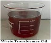
The oil-KOH-alcohol solution is stirred at 60°C for two hours before being transferred to a glass container. Now a separation occurs, with the biodiesel collecting in the top portion of the glass container and the glycerine at the bottom. The glycerine is taken out of the bottle. After that, water is used to wash the biodiesel. Once more, glycerine is extracted and isolated from biodiesel. Biodiesel is continually rinsed with water until there is no longer any glycerine in the biodiesel. The water content in this biodiesel is now vaporized by heating it to 100°C. Figures 2 and 3 show the waste transformer oil and biodiesel.

2.2. TBC coating process
Zirconia material is capable of being stable at different temperatures and transforms itself from a monoclinic phase at 1200°C to a transformed phase beyond 1200°C and at temperatures above 2370°C, it is reported to have transformed to a cubic phase. The bond coat’s main goal is to shield the steel base from corrosion, especially from O2 and other caustic substances that can flow over permeable clay peak cover. To avoid recontamination on the cleaned rough surface after the blast gritting process without disturbing the grid surface, the piston is modified for bond coating quickly. The piston is securely secured in the fixture to prevent coating material from spaying into the lateral surfaces of the piston; only the top surfaces are coated. Before beginning the actual bond coating, the coated surface is preheated to a temperature of about 60°C. With suitable pass thickness and particle size control, 0.15 mm of Gd2O7Zr2 is used as the bond coating material in the current work. During the coating process, the correct settings and torch (Table 1), including current, voltage, and gas flow, are set. The surface is prepped for appropriate top coating adherence following the bond coating once more. Figure 4 (a) and (b) show uncoated and coated.

2.3. Nanoparticle
The fuel blends B10, B20, and B30 all contain nanoparticles. To achieve uniform suspension, 30 ppm of alumina nanoparticles are added to the fuel mixes using an ultrasonicator. D90 + B10 + 30 ppm, D80 + B20 + 30 ppm, and D70 + B30 + 30 ppm are some of the mixes that were achieved and Figure 5 shows the molecular structure of the nano additive.

2.4. Experimental setup
In the present investigation process, a single-cylinder, air-cooled vertical diesel engine is employed. It is outfitted with an exhaust emission measurement system, a computerized combustion analyzer, and eddy current dynamometer loading. Table 2 is a list of the key engine technical specifications. It includes a single-cylinder diesel motor with an eddy current dynamometer and the ability to manually vary the load from 0 to 100% by adjusting the current flow through the dynamometer. Figure 6 shows the layout of the instruments used to measure fuel consumption and other pertinent emissions. Figure 7 shows the Photographic view.


3. RESULTS AND DISCUSSION
The main objective of the present study is to evaluate how piston coating impacts an engine’s ability to run on a mixture of diesel and biodiesel. For five distinct load conditions of covered diesel and biodiesel blends, critical engine performance metrics of brake-specific fuel consumption, brake thermal efficiency, also indicated mean effective pressure are reviewed.
3.1. Performance and emission analysis
3.1.1. Brake specific fuel consumption
It has been shown in Figure 8 with brake power for the current investigation. The specific fuel expenditure for the three coated B10, B20, and B30 piston engines is higher at low load and lower at peak load as compared to low load consumption. Fuel consumption of B10-coated material is 15 kg/kWh at low load, which is 4% more than that of B20-coated material and 3.5% more than that of B30-coated material. Additionally, the B20-coated material uses 11 kg/kWh of fuel during periods of low load, a.5% increase over the 10.5 kg/kWh of fuel used by the B30-coated material. The three coated piston engines B10, B20, and B30 each use 1.3 kg/kWh of gasoline while operating at average load. The three coated piston engines B10, B20, and B30 also use the same amount of fuel (1 kg/kWh) during peak load. Additionally, this is rather modest when compared to the mean and low loads of brake power.

3.1.2. Indicated mean effective pressure
Due to its independence from engine size or speed, mean effective pressure is a crucial parameter to compare when designing. It is a useful gauge of the engine’s ability to perform the task and provides a clear indicator of the engine’s indicated power. For the current study, the change of braking power with the given mean effective pressure is depicted in Figure 9. The indicated mean effective pressure for the three coated piston engines B10, B20, and B30 is low compared to the mean load at low brake power load and is even lower compared to peak brake power load. Additionally, the three coated materials B10, B20, and B30 consume the same amount of pressure (1-2 bars) with low brake power. The three coated materials will have the same pressure level of 4.5 bar when there is a mean load of brake power once more. The three coated materials B10, B20, and B30 will retain the same pressure level of 7.2 bar at the final peak load. It is concluded from the graph, Figure 8 that the mean effective pressure is high when the brakes are operating at their maximum capacity.

3.1.3. Carbon monoxide (Co)
The emission of CO from a diesel motor is partially caused by incomplete combustion, poor mixing, a localized oxygen shortage, the commencement of injection, a localized rich zone, and quenching. Figure 10, below, illustrates how CO emission levels vary with braking power. The three coated piston engines B10, B20, and B30 in this graph will emit less CO at low load than at mean load, which will in turn emit less CO than at peak load. The coated piston engine B10 emits significantly more CO (.25%) than the coated piston engines B20 and B30 while operating at low loads. Poor combustion results from inadequate time for proper mixing with air and mixture vaporization. The CO emission level for the B10 is 0.79%, which is 18% higher than the CO emission level for the B20 and B30, respectively. Finally, B30 blend shows a positive approach with thermal barrier coating for pistons.

3.1.4. Hydrocarbons
Due to insufficient temperature near the cylinder wall, fuels that are not burnt produce hydrocarbon discharges. The temperature of the air-fuel mixture is significantly lower than the centre of the cylinder right away. The majority of diesel hydrocarbon emissions occur under light tons. Light-load hydrocarbon discharges are mostly caused by lean air-fuel blending; under these circumstances, combustion may not occur or may occur at speeds too low to complete it during the power stroke. Figure 11 illustrates the change in brake power and hydrocarbon emission levels. The B10-coated piston engines have a hydrocarbon emission level of 20PPM at low load, which is 10% more than the B20s and 13% more than the B30s. The B10-coated engine releases hydrocarbon at a range of 50PPM during mean brake load. The hydrocarbon emissions from B20 and B30 are 25PPM and 18PPM, respectively. The B10 coated engine generates 158PPM of hydrocarbon at maximum brake load. B20 then emits 118 PPM of hydrocarbon, and B30 emits 83 PPM. It is arrived that B30 is the best coating material for piston engines. Because during high load it emits very little hydrocarbon.

3.1.5. Carbon dioxide
Fossil fuel use significantly increases CO2 emissions, which is the main cause of the greenhouse effect and global warming. Figure 12, illustrates how CO2 emission release varies with braking power. The three-coated piston engines B10, B20, and B30 have low carbon dioxide emission levels when operating under low brake power compared to mean load three-coated piston engines, which in turn have low emission levels when operating under peak load three-coated engines. The B30-coated piston material emits a high level of carbon dioxide (2.1%) during low load, which is (2%) more than the emissions of the B10 and B20-coated piston materials. Additionally, at the mean load, B30 coated material’s carbon dioxide emission level increased to 6%, which is (.2%) higher than that of B10 and B20 coated material (5.8% and 5.8%, respectively). At peak load, the carbon dioxide emissions from the B20 and B30 coated materials will be equal (11%), and they will be (.25%) higher than those from the B10 coated materials (10.5%). The graph analysis reveals that B10 is the best coating material for reducing carbon dioxide emissions.

3.1.6. Oxides of nitrogen release
Diesel engines are the main source of nitrogen oxide emissions because of the reaction time and high-temperature combination that occurs during combustion. The air-fuel ratio, percentage of burned exhaust gas, response time, or length of combustion inside the combustion chamber are significant factors that affect NOx formation. It is created by a series of high-temperature chain reactions involving the nitrogen and oxygen components of the air. Since diesel fuel engines always run at lean mixes, the temperature and residence time of the combustion gas are the main factors influencing NOx emissions. Figure 13 below illustrates how brake power and nitrogen oxide emission levels vary. The three-coating piston engines emit 100 PPM of nitrogen oxides when the brakes are not being used much. Additionally, the B20 and B30 have the same level of nitrogen oxide emissions at average brake load, which is 9000 PPM, which is (20%) higher than the emission level of B10 coated material (880 PPM). At maximum braking force, the B10 and B20 emit the same amount of nitrogen oxides (1430 PPM), which is 30% more than the 1400 PPM emission limit of the B30-coated piston material. The graph’s conclusion demonstrates that the B30 coated material is the most appropriate because it emits little nitrogen oxide under peak load.

3.2. Combustion analysis
Analyse the characteristics of diesel and biodiesel mixtures as well as Transformer oil combustion, combustion analysis is carried out on coated engines. In diesel engines, combustion is one of the most significant and challenging processes. At a rated injection pressure of 200 bar, the fuel is inserted into the expenditure chamber in current experimental research. Effects of varying inserted pressure also inserted time on expenditure properties are also investigated to examine the viability of using waste transformer biodiesel in engines. Results are only recorded once the combustion process has reached a steady state to obtain accurate combustion information. To learn more about the combustion phenomenon, the chart’s information on peak pressure release rates, heat releases, and ignition delays is used.
3.2.1. Peak pressure release
When the air and fuel in a diesel engine start burning, the pressure inside the combustion chamber rises. This pressure rises further until it reaches a peak. Figure 14 shows the peak pressure readings for 180°of crank rotation that are taken from the combustion analysis program. The graph demonstrates that for all test conditions, the peak pressure rises with the load. Figure 13 shows that the advanced injection case with the B10 coated piston engine reaches the highest peak pressure, which is 38 bar, this happens due to high temperature of the insulated piston crown, along with earlier combustion. It happens which outcomes of the expenditure process amassing more fuel and releasing a relatively high peak pressure. For B10-coated piston engines, the fall in peak pressure is observed during retardation; it may be caused by a shorter ignition and a suppressed peak pressure level.

3.2.2. Rate of heat release
After the compression stroke in diesel engines, the injector injects fuel into the cylinder. During that time, the combustion chamber’s air temperature and pressure are noticeably higher; the fuel vaporizes and mixes with the hot air. After a few rotations of the crank angle, the combustible mixture spontaneously ignites once it reaches the fuel’s self-ignition temperature. The sections that follow explore this significant phenomenon.
The ignition delay is the length of time that passes between the beginning of the fuel shot into the expenditure compartment also the beginning of expenditure. This is a crucial component of the engine fuel. The rate of heat release in heat free curve is a sign of a type of firing taking place inside the engine’s combustion chamber. It can offer details on the beginning of the injection, the injection, and the location and timing of the peak release. Understanding this information on combustion shows how utilized fuel behaves in terms of performance indicators and emission outputs. The heat release curve for covered piston B10 with fuel test is shown in Figure 15. It can be seen from the chart and output graph of the combustion analyzer that the combustion process begins around 23°CA BTDC and peaks at 22 kJ/deg, which is higher than that of a normal motor. Along the B10-covered piston motor, the peak temperature of the coated piston allows for faster combustion and more heat production.

3.2.3. Ignition delay evaluation
The combustion analysis output chart, which shows a steep slope on the curve before reaching peak pressure, is used to determine the ignition delay for a given test (Heywood 1998). According to Lakshminarayanan and Yogesh, the pre-combustion reactions cause a chemical delay during the ignition delay phase in addition to the physical delay caused by fragmentation, vaporization, also blending of fuel and air. In a real engine, the compression stroke is where the fuel injection starts at position B (at rated injection 24°CA BTDC). It takes some time for mixing, atomization, and vaporization before the fuel injection ignites. Point C is where the ignition starts. The pressure in the combustion chamber does not increase above the compression curve during the crank movement from B to C. The term “delay period” or “ignition delay” refers to the duration that corresponds to the crank angle B to C. The test fuel viscosity and flash point have an important influence on the lighting defer. The density also viscosity of the fuel determine how easily diesel or biodiesel atomizes and vaporizes. Among the first fuel shots also beginning of expenditure is this period. Figure 16 shows the crank angle commencement of combustion and the ignition delay for coated piston engine B10 as retrieved from the heat release curve. According to estimates, the coated piston engine B10’s hot environment causes a 70% reduction in ignition latency.

4. CONCLUSION
Without making any significant changes to the motor, the TBC (Gd2O7Zr2) on bond coat AlNiCr is effectively applied and tested in the air-cooled diesel motor piston. The use of 100% transformer oil as biodiesel and its blends (10%,20%, and 30%) is investigated, and it is found to have enhanced thermal productivity, an important diminish in brake-specific fuel expenditure, also a significant reduction in emissions. From the standpoints of fuel efficiency and engine performance in coated piston engines, the study concludes that 100% Transformer oil as biodiesel is a suitable substitute for diesel. However, a careful balance between injection pressure and timing is required to achieve the ideal level of NOx and smoke emissions. In this case, the primary goal of the current work is viewed as having been accomplished because the engine’s performance is enhanced while using Transformer oil as biodiesel in an engine with coated pistons. At peak loading, there is a 5% increase in thermal productivity. It has been discovered that a coated piston engine with TF uses less gasoline (14.4%), proving that coating the piston crown improves fuel efficiency. When compared to coated diesel engines at rated injection, coated transformer oil as fuel results in a 14% reduction in smoke. It demonstrates that TF fuel-coated pistons emit less smoke than diesel fuel matched to diesel fuel.
5. BIBLIOGRAPHY
-
[1] YANG, Z.G., LIANG, W.P., MIAO, Q., et al, “Hot corrosion behaviors of as-sprayed and laser-remelted YSZ thermal barrier coatings at 950° C”, Matéria (Rio de Janeiro), v. 27, n. 3, pp. e20220052, 2022. doi: http://doi.org/10.1590/1517-7076-rmat-2022-0052.
» https://doi.org/10.1590/1517-7076-rmat-2022-0052. -
[2] MA, T., CHEN, D., WANG, H., et al, “Influence of thermal barrier coating on partially premixed combustion in internal combustion engine”, Fuel, v. 303, pp. 121259, 2021. doi: http://doi.org/10.1016/j.fuel.2021.121259.
» https://doi.org/10.1016/j.fuel.2021.121259 -
[3] CIHAN, Ö., TEMIZER, İ., GÖK, M.G., et al, “Investigation of the effect of rare earth doped La2Zr2O7 based thermal barrier coating on performance and combustion characteristics of DI diesel engine”, Surface and Coatings Technology, v. 403, pp. 126437, 2020. doi: http://doi.org/10.1016/j.surfcoat.2020.126437.
» https://doi.org/10.1016/j.surfcoat.2020.126437 -
[4] SHARMA, S.K., OJHA, K.V., BHARDWAJ, S. Thermal stress analysis and parametric study of thermal barrier coated engine piston. In Sharma, V.K., Kumar, A., Gupta, M., Kumar, V., Sharma, D.K., Sharma, S. K. (eds.), Additive Manufacturing in Industry 4.0 Boca Raton, CRC Press, pp. 125–140, 2022. doi: http://doi.org/10.1201/9781003360001-7.
» https://doi.org/10.1201/9781003360001-7 -
[5] GANGULA, V.R., NANDHANA GOPAL, G.R., TARIGONDA, H., “Experimental analysis and energy balance on thermal barrier-coated piston diesel engine using biodiesel”, Journal of The Institution of Engineers Series C, v. 101, n. 6, pp. 1015–1026, 2020. doi: http://doi.org/10.1007/s40032-020-00604-4.
» https://doi.org/10.1007/s40032-020-00604-4. -
[6] HEGAB, A., DAHUWA, K., ISLAM, R., et al, “Plasma electrolytic oxidation thermal barrier coating for reduced heat losses in IC engines”, Applied Thermal Engineering, v. 196, pp. 117316, 2021. doi: http://doi.org/10.1016/j.applthermaleng.2021.117316.
» https://doi.org/10.1016/j.applthermaleng.2021.117316 - [7] ANDRIE, M., KOKJOHN, S., PALIWAL, S., et al, “Low heat capacitance thermal barrier coatings for internal combustion engines”, SAE Technical Paper, 2019-01-0228, 2019.
-
[8] MOHSIN, R., MAJID, Z.A., SHIHNAN, A.H., et al, “Effect of biodiesel blends on engine performance and exhaust emission for diesel dual fuel engine”, Energy Conversion and Management, v. 88, pp. 821–828, 2014. doi: http://doi.org/10.1016/j.enconman.2014.09.027.
» https://doi.org/10.1016/j.enconman.2014.09.027 -
[9] ELUMALAI, P.V., ANNAMALAI, K., DHINESH, B., “Effects of thermal barrier coating on the performance, combustion and emission of DI diesel engine powered by biofuel oil-water emulsion”, Journal of Thermal Analysis and Calorimetry, v. 137, n. 2, pp. 593–605, 2019. doi: http://doi.org/10.1007/s10973-018-7948-6.
» https://doi.org/10.1007/s10973-018-7948-6. -
[10] RAVIKUMAR, V., SENTHILKUMAR, D., SOLAIMUTHU, C., “Experimental investigation of performance and emissions of an Al-20% SiC coated diesel engine with Madhuca indica biodiesel”, International Journal of Ambient Energy, v. 34, n. 3, pp. 131–137, 2013. doi: http://doi.org/10.1080/01430750.2012.740427.
» https://doi.org/10.1080/01430750.2012.740427. -
[11] SABARISH, R., GOLDEN RENJITH NIMAL, R.J., RAJASEKAR, R., et al, “Effects of injection pressure on performance and emission characteristics of CI engine using Waste Cooking Oil (WCO) blend”, Journal of Mines Metals and Fuels, v. 71, n. 9, pp. 1286–1292, 2023. doi: http://doi.org/10.18311/jmmf/2023/35460.
» https://doi.org/10.18311/jmmf/2023/35460. -
[12] DOLEKER, K.M., OZGURLUK, Y., KARAOGLANLI, A.C., “Isothermal oxidation and thermal cyclic behaviors of YSZ and double-layered YSZ/La2Zr2O7 thermal barrier coatings (TBCs)”, Surface and Coatings Technology, v. 351, pp. 78–88, 2018. doi: http://doi.org/10.1016/j.surfcoat.2018.07.069.
» https://doi.org/10.1016/j.surfcoat.2018.07.069 -
[13] RAMASAMY, N., KALAM, M.A., VARMAN, M., et al, “Effect of thermal barrier coating on the performance and emissions of diesel engine operated with conventional diesel and palm oil biodiesel”, Coatings, v. 11, n. 6, pp. 692, 2021. doi: http://doi.org/10.3390/coatings11060692.
» https://doi.org/10.3390/coatings11060692. -
[14] DHOMNE, S., MAHALLE, A.M., “Thermal barrier coating materials for SI engine”, Journal of Materials Research and Technology, v. 8, n. 1, pp. 1532–1537, 2019. doi: http://doi.org/10.1016/j.jmrt.2018.08.002.
» https://doi.org/10.1016/j.jmrt.2018.08.002. -
[15] ODABAS, O., OZGURLUK, Y., OZKAN, D., et al, “Investigation of vermiculite infiltration effect on microstructural properties of thermal barrier coatings (TBCs) produced by electron beam physical vapor deposition method (EB-PVD)”, Surface and Coatings Technology, v. 443, pp. 128645, 2022. doi: http://doi.org/10.1016/j.surfcoat.2022.128645.
» https://doi.org/10.1016/j.surfcoat.2022.128645 -
[16] ELUMALAI, P.V., NAMBIRAJ, M., PARTHASARATHY, M., et al, “Experimental investigation to reduce environmental pollutants using biofuel nano-water emulsion in thermal barrier coated engine”, Fuel, v. 285, pp. 119200, 2021. doi: http://doi.org/10.1016/j.fuel.2020.119200.
» https://doi.org/10.1016/j.fuel.2020.119200 -
[17] PAPARAO, J., PANDEY, K.K., MURUGAN, S., “Experimental studies on the effect of TBC piston in a dual-fueled diesel engine”, Fuel, v. 306, pp. 121700, 2021. doi: http://doi.org/10.1016/j.fuel.2021.121700.
» https://doi.org/10.1016/j.fuel.2021.121700 -
[18] SHAISUNDARAM, V.S., SARAVANAKUMAR, S., BALAMBICA, V., et al, “Effects of thermal barrier coating using various dosing levels of aluminium oxide nanoadditive fuel on diesel in compressed ignition engine”, Journal of Nanomaterials, v. 2022, n. 1, pp. 8355098, 2022. doi: http://doi.org/10.1155/2022/8355098.
» https://doi.org/10.1155/2022/8355098. -
[19] FEI, C.G., QIAN, Z.Q., REN, J., et al, “Numerical and experimental research on thermal insulation performance of marine diesel engine piston based on YSZ thermal barrier coating”, Coatings, v. 11, n. 7, pp. 765, 2021. doi: http://doi.org/10.3390/coatings11070765.
» https://doi.org/10.3390/coatings11070765. -
[20] LIU, Y., LEI, J., NIU, X., et al, “Experimental and simulation study on aluminium alloy piston based on thermal barrier coating”, Scientific Reports, v. 12, n. 1, pp. 10991, 2022. doi: http://doi.org/10.1038/s41598-022-15031-x. PubMed PMID: 35768492.
» https://doi.org/10.1038/s41598-022-15031-x. -
[21] ERDOĞAN, S., AYDIN, S., BALKI, M.K., et al, “Operational evaluation of thermal barrier coated diesel engine fueled with biodiesel/diesel blend by using MCDM method base on engine performance, emission and combustion characteristics”, Renewable Energy, v. 151, pp. 698–706, 2020. doi: http://doi.org/10.1016/j.renene.2019.11.075.
» https://doi.org/10.1016/j.renene.2019.11.075 - [22] RAMACHANDRAN, T.N., RAO, Y.S., SRINIVASNAIK, M., et al, “Performance augmentation and emission reduction in diesel engines using HfC-coated pistons with biodiesel blends”, Thermal Science, v. 28, n. 1, pp. 209–221, 2024.
-
[23] GANGULA, V.R., NANDHANA GOPAL, G.R., TARIGONDA, H., “Investigation on different thermal barrier-coated piston engines using Mahua biodiesel”, Journal of The Institution of Engineers Series C, v. 102, n. 1, pp. 131–144, 2021. doi: http://doi.org/10.1007/s40032-020-00621-3.
» https://doi.org/10.1007/s40032-020-00621-3. -
[24] VENU, H., APPAVU, P., “Analysis on a thermal barrier coated (TBC) piston in a single cylinder diesel engine powered by Jatropha biodiesel-diesel blends”, SN Applied Sciences, v. 1, n. 12, pp. 1669, 2019. doi: http://doi.org/10.1007/s42452-019-1771-y.
» https://doi.org/10.1007/s42452-019-1771-y. -
[25] VALIVETI, S.R.K., SHAIK, H., REDDY, K.V.K., “Analysis on impact of thermal barrier coating on piston head in CI engine using biodiesel”, International Journal of Ambient Energy, v. 43, n. 1, pp. 3377–3384, 2022. doi: http://doi.org/10.1080/01430750.2020.1831592.
» https://doi.org/10.1080/01430750.2020.1831592 -
[26] RAMASAMY, N., KALAM, M.A., VARMAN, M., et al, “Effect of thermal barrier coating on the performance and emissions of diesel engine operated with conventional diesel and palm oil biodiesel”, Coatings, v. 11, n. 6, pp. 692, 2021. doi: http://doi.org/10.3390/coatings11060692.
» https://doi.org/10.3390/coatings11060692. -
[27] GANGULA, V.R., NANDHANA GOPAL, G.R., TARIGONDA, H., “Experimental analysis and energy balance on thermal barrier-coated piston diesel engine using biodiesel”, Journal of The Institution of Engineers Series C, v. 101, n. 6, pp. 1015–1026, 2020. doi: http://doi.org/10.1007/s40032-020-00604-4.
» https://doi.org/10.1007/s40032-020-00604-4. -
[28] PERUMAL VENKATESAN, E., KANDHASAMY, A., SIVALINGAM, A., et al, “Performance and emission reduction characteristics of cerium oxide nanoparticle-water emulsion biofuel in diesel engine with modified coated piston”, Environmental Science and Pollution Research International, v. 26, n. 26, pp. 27362–27371, 2019. doi: http://doi.org/10.1007/s11356-019-05773-z. PubMed PMID: 31325093.
» https://doi.org/10.1007/s11356-019-05773-z


 Source: Sri Venkateswara College of Engineering, Sriperumpudur, Chennai 602117.


