 Shear strength evaluation of synthetic microfiber and macrofiber reinforced concrete beams
Abstract
Abstract This study investigates the use of synthetic fibers—glass, polyester, polypropylene, and polyethylene—in reinforced concrete beams to assess their contribution when the structural element is subjected to shear stress. The methodology began with the characterization of the concrete constituents (cement, fine and coarse aggregates, and fibers), following the EPUSP-IPT Concrete Dosing method. Subsequently, the beams were cast as follows: one (1) reference beam without added fibers and twelve (12) beams with added macrofibers—three (3) beams for each fiber type (fiberglass, polyester, polypropylene, and polyethylene). Shear performance was then evaluated through experimental beam failure testing. Glass and polyester microfibers contributed to post-peak or post-cracking stability, reducing the likelihood of sudden failure. Their contribution to shear strength gain was 15.1% for VFV01 (beam with 0.024% glass microfiber) and 21.6% for VFPO02 (beam with 0.032% polyester microfiber), both relative to the reference beam (VR). Regarding the polypropylene and polyethylene macrofibers, it was observed that increasing the fiber content in the concrete mix led to greater ductility. Among the tested fiber contents, 0.36% and 0.48% polyethylene and 0.16% polypropylene represented critical percentages, indicating values close to the optimal fiber content. This suggests that the composite's load-bearing capacity approached the matrix failure threshold. Therefore, this study demonstrates that fiber reinforcement can be effectively used to control and enhance the shear performance of structural concrete. This composite presents itself as a promising partial substitute for transverse reinforcement—namely, stirrups in beams—by reducing the likelihood of sudden failure. Glass, polyester, polypropylene, and polyethylene fibers, at certain percentages, contributed to increased shear strength and toughness of the concrete.
Keywords:
shear; beams; fiber types; reinforced concrete; structural elements
Resumo
Resumo O presente estudo realiza a avaliação da aplicação de teores de fibras sintéticas de vidro, poliéster, polipropileno e polietileno em vigas de concreto armado, de modo a comprovar as devidas contribuições, quando tal elemento estrutural for submetido à tensão de cisalhamento. Neste contexto, a metodologia baseou-se primeiramente na caracterização dos materiais constituintes do concreto (cimento, agregados miúdos e graúdos e as fibras), tendo como premissas o método de Dosagem de Concreto EPUSP-IPT; em seguida, a concretagem das vigas foi realizada da seguinte maneira: uma (01) de referência sem adição de fibras e doze (12) com adições de microfibra de vidro e poliéster, e macrofibra de polipropileno e polietileno, sendo três (3) para cada uma das referidas; e posterior análise quanto ao cisalhamento por meio dos rompimentos das vigas experimentais. As microfibras de vidro e poliéster contribuíram para estabilidade com relação ao pós-pico ou pós-fissuração, o que reduz a possibilidade de ruptura súbita; essa contribuição no ganho na resistência ao cisalhamento foi 15,1% para a VFV01 (viga com adição de microfibras vidro com o percentual de 0,024%) e de 21,6% da VFPO02 (viga com adição de microfibra de poliéster com percentual de 0,032%) ambas em relação a VR (viga de referência); já para as macrofibras polipropileno e polietileno, pôde-se constatar que, à medida que se incrementou teores de ambas as fibras ao concreto produzido, o mesmo se tornou mais dúctil, visto que, dentre os teores de fibras utilizados, os percentuais de 0,36% e 0,48% de polietileno e 0,16% de polipropileno foram os que apresentaram um percentual crítico correspondente ao teor de fibras próximo a um ideal, demonstrando assim, a proximidade da capacidade portante para o compósito a partir da ruptura da matriz. Logo, este estudo demostrou que o reforço fibroso pode ser usado com eficiência no controle e bem como melhoria do desempenho ao cisalhamento em concreto estrutural, pois este compósito demonstra ser promissor na substituição parcial das armaduras transversais, isto é, os estribos em vigas, o que reduz a possibilidade de ruptura súbita pois as fibras de vidro, poliéster, polipropileno e polietileno para alguns percentuais aumentaram a resistência ao cisalhamento e tenacidade do concreto.
Palavras-chave:
cisalhamento; vigas; tipos de fibra; concreto armado; elementos estruturais
1 INTRODUCTION
As the most widely used material in construction, concrete has undergone extensive research over the years, leading to the development of various types tailored for different structural applications. More recently, studies have focused on the reinforcement of concrete structures, which result from the combination of concrete and steel. This synergy creates a mutual relationship between the two materials: steel provides the hardened structure with the capacity to resist tensile stresses, while cured concrete protects the steel from aggressive agents that could lead to corrosion.
In addition, researchers have been exploring the incorporation of fibers into concrete to enhance its ductility and toughness, as concrete is prone to developing microcracks under cyclic loading, which can compromise its durability. To mitigate these issues in reinforced concrete structural elements, the use of fibers has shown improvements in fatigue resistance.
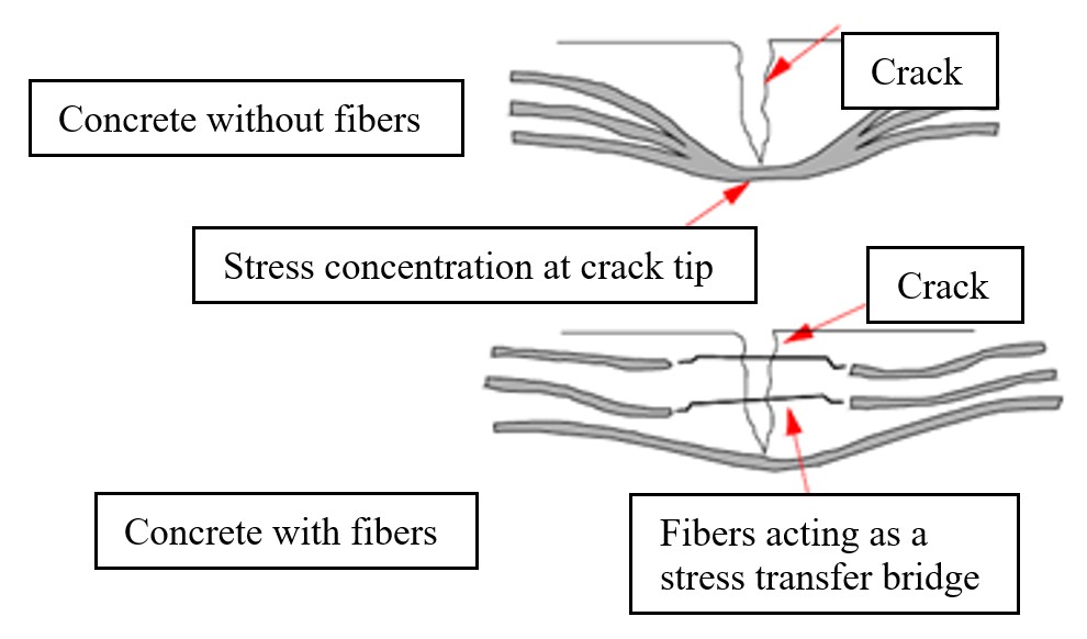
Studies have shown that, within a concrete matrix, fibers help prevent the formation of microcracks during the hardening of the cement paste. This inhibits crack propagation and delays the onset of macrocracks, thereby enhancing the durability of the concrete. By incorporating fibers with suitable strength and modulus of elasticity at appropriate content levels, the material loses its brittle nature. The fibers act as stress-transfer bridges (Figure 1), significantly reducing crack propagation within the composite [1].

As previously mentioned, numerous studies have investigated the incorporation of fibers into concrete. However, in Brazil, until around 2020, there were no regulatory standards addressing the use of fibers as shear reinforcement. Additionally, research on synthetic fibers as structural reinforcement was limited, with most studies focusing on steel and carbon fibers. This created a gap in the assessment of synthetic fiber feasibility for shear reinforcement applications. With the introduction of ABNT NBR 16935:2021 – Design of Fiber-Reinforced Concrete Structures, the use of fibers for shear reinforcement began to be formally addressed [2]. According to this standard, fiber-reinforced concrete (FRC) is defined as a composite material consisting of a cementitious matrix and discrete fibers that are stable in alkaline environments. These fibers serve as structural reinforcement to enhance FRC performance under both ultimate limit state (ULS) and service limit state (SLS) conditions, and may be used either independently or in combination with active and passive reinforcement [2].
In fact, when fibers are incorporated, the primary mechanical property affected is the post-cracking residual tensile strength, which is a key design parameter for fiber-reinforced concrete (FRC) structures [3]. The enhanced post-cracking performance, increased ductility, and improved residual tensile strength of FRC have been acknowledged by several authors. This behavior also enables the accommodation of large deformations, improving stress redistribution and allowing energy absorption prior to structural failure [4].
The methodology began with the characterization of the materials comprising the concrete—cement, fine and coarse aggregates, and fibers—based on the EPUSP-IPT Concrete Dosage method. The beams were then cast as follows: one (1) reference beam without fiber addition and twelve (12) beams with added fibers—three (3) beams for each type of fiber: glass microfiber, polyester microfiber, polypropylene macrofiber, and polyethylene macrofiber. These beams were subsequently tested in shear through experimental failure analysis.
The objective of this research was to evaluate the contribution of varying mass percentages of synthetic macrofibers. For polypropylene, fiber contents of 0.08%, 0.12%, and 0.16% were used; for polyethylene, 0.24%, 0.36%, and 0.48%. These values were selected based on the supplier’s recommendation of 3 to 12 kg/m3 of concrete [5]. For glass and polyester microfibers, contents of 0.024%, 0.036%, and 0.042% were adopted, also based on the supplier’s guidance of 0.6 to 1.2 kg/m3 of concrete [5]. All fibers were incorporated into conventional concrete to assess their contribution to the shear performance of structural elements.
2 LITERATURE REVIEW
This chapter was developed to outline the necessary steps for studying shear reinforcement in beams incorporating glass and polyester microfibers, as well as polypropylene and polyethylene macrofibers. To provide a clearer understanding of the research context, the literature review was organized into two main areas, namely: (1) reinforcement in beams using glass and polyester microfibers, and (2) reinforcement in beams using polypropylene and polyethylene macrofibers.
2.1 A Brief History
As described in Neville and Brooks [6], concrete—broadly defined—is any product or mass formed using a cementing medium, typically resulting from the reaction between hydraulic cement and water. Consequently, concrete can be produced with various types of cement and may include pozzolanic materials such as fly ash, blast furnace slag, and silica fume, along with mineral additions, recycled concrete aggregates, chemical admixtures, polymers, and fibers.
Fiber-reinforced concrete (FRC) has been in use since the 1960s. Today, it is applied across a wide range of civil construction elements, including roof tiles, vertical sealing panels, and structural components such as tunnels and sidewalks—areas where its use has steadily expanded [7]. As a result, the market now offers a diverse array of fiber types, including steel, polypropylene, carbon, glass, nylon, cellulose, acrylic, polyethylene, wood, and sisal.
2.2 Concrete
Concrete has a wide range of properties and characteristics that make it the most widely used structural material in the world [8]. Modern construction techniques demand specific and enhanced forms of concrete, including high-performance concrete, high-strength concrete, concrete with elevated pozzolanic content, exposed concrete, colored concrete, white concrete, self-compacting concrete, fiber-reinforced concrete, and sustainable concrete, among others [9].
2.3 Fiber-Reinforced Concrete
Fiber-reinforced concrete (FRC) has emerged as an alternative to traditional materials such as plain concrete and steel in various structural and non-structural applications. FRC is composed of cement, fine and coarse aggregates, water, and fibers. These fibers can vary in size and shape and may be made from steel, glass, plastic, or natural materials. Among these, steel fibers are the most commonly used in both structural and non-structural elements [10].
The incorporation of fibers enhances the tensile capacity of concrete and influences how its overall strength is calculated. It also improves crack control by increasing resistance to wear caused by impact, shrinkage, thermal stresses, and fatigue. Moreover, fibers significantly alter the mechanical behavior of hardened concrete, contributing to better crack propagation control and improving the performance of structural elements under tensile stress—ultimately enhancing concrete durability [11].
As a result, fiber-reinforced concrete can be defined as a composite material composed of at least two distinct phases. While conventional concrete is already considered a composite—comprising paste, pores, and aggregates—FRC is characterized by a matrix of concrete and embedded fibers, which may be made from materials such as steel, glass, polypropylene, or nylon [12].
2.4 Fiber types
Table 1 shows the main types of fibers that have been studied and applied as additions to concrete. Each fiber type possesses intrinsic properties that, when incorporated, are transferred to the concrete matrix, influencing its mechanical behavior and overall performance [13].
Fibers are generally classified into natural and manufactured types. Manufactured fibers can be further divided into artificial and synthetic categories. Natural fibers, in turn, are classified as vegetable—composed primarily of cellulose, lignin, and hemicellulose; mineral—extracted from specific types of rock; and animal—derived from secretions or hair and composed of proteins [14].
The use of fibers to reinforce brittle matrices dates back to ancient times. One of the earliest recorded examples is the use of straw or grass as reinforcement in sun-dried clay bricks, as referenced in Exodus 5:6–7: ‘And Pharaoh gave the following order: Do not give the people any more straw to make bricks, as they did before. Let them gather straw for themselves.’ This historical account illustrates the long-standing practice of using fibrous materials to improve the structural integrity of composite systems [15].
Fibers play a key role in determining the stiffness and strength of composite materials, with these properties varying according to the fiber's concentration, size, type, and orientation within the matrix. Maximum stiffness and strength are achieved when fibers are aligned with the principal stress direction; deviations from this alignment result in reduced performance, reaching a minimum when fibers are oriented perpendicular to the main direction [16].
The modulus of elasticity and mechanical strength of the fibers are intrinsic properties of the fiber material and are the primary factors influencing its reinforcement capacity in concrete [7]. Additionally, fibers can be incorporated into concrete to promote more ductile behavior, enhance crack control, and improve stiffness—contributing to better structural performance and durability [17].
2.4.1 Macrofibers and Microfibers
Macrofibers enhance resistance to plastic shrinkage cracking and contribute to increased durability, toughness, and limited structural strength in concrete. They are designed to be dosed in quantities comparable to conventional steel reinforcement—such as rebar and welded wire mesh—and are uniformly distributed in three dimensions throughout the concrete matrix [18].
A notable example is the structural synthetic macrofiber produced by Neomatex, which improves the composite’s tensile strength and imparts ductile behavior. This enhances structural safety by allowing visible signs of overstress to appear before failure, providing time for corrective intervention. However, it is important to note that fiber addition may affect the concrete’s workability and, in some cases, its long-term durability [19].
Microfibers exhibit high resistance to plastic shrinkage cracking when compared to steel mesh; however, they do not provide significant strength against crack opening caused by hydraulic shrinkage, structural loading, or other stress mechanisms. Nevertheless, microfibers can be incorporated into any type of concrete to enhance crack resistance, reduce spalling, improve durability, and promote homogeneity during casting [18].
In this context, glass fiber-reinforced polymer (GFRP) is produced by melting siliceous materials—primarily sand—highlighting its inorganic origin [20].
2.5 Basic shear strength mechanisms
From a structural perspective, the primary reason for incorporating fibers into concrete is to enhance its fracture behavior—particularly by bridging cracks and improving post-cracking performance (Figure 2). This influence is evident in both service and ultimate limit states.

At the service limit state, fibers help control crack propagation, leading to reduced crack spacing and width, as well as increased flexural stiffness. At the ultimate limit state, fibers contribute to higher load capacity, improved punching and shear strength, and enhanced ductility [13].
In beams without shear reinforcement, the first inclined crack typically forms—or diagonal tension failure occurs—shortly after loading begins. Several parameters influence the load at which diagonal cracking initiates, including the concrete’s compressive strength, the effective depth of the beam, and the longitudinal reinforcement ratio. However, the combined influence of these parameters is not explicitly accounted for in most design standards. As a result, the predicted diagonal cracking loads are often higher than those observed experimentally, which may lead to unsafe design assumptions [1].
Shear failure typically initiates with the formation of inclined cracks, resulting from the combined effects of shear force, bending moment, and, in some cases, axial forces. A wide range of variables influence this type of failure, including beam geometry, cross-sectional dimensions, concrete strength, the amount and arrangement of longitudinal and transverse reinforcement, loading conditions, and span length. Due to the complex and nonlinear behavior of beams under shear, accurate design remains a significant challenge. As a result, shear behavior continues to be one of the most extensively studied topics in structural engineering, both historically and in current research [21].
According to Medeiros [1], beams subjected to shear may exhibit three distinct types of failure, namely: a) Flexural failure: This is a ductile mode of rupture, characterized by cracks forming approximately orthogonal to the longitudinal reinforcement in regions where tensile stress reaches its peak, exceeding the tensile strength of the concrete; b) Diagonal tension failure: Following the development of flexural cracks, inclined cracks emerge due to diagonal tension. These typically occur in the intermediate zones between supports and midspan, where principal tensile stresses surpass the concrete’s tensile strength. This failure mode is common in prestressed beams and often results in sudden rupture due to the combined action of bending and shear forces; c) Compression failure at the top combined with diagonal tension: After initial flexural cracks appear, diagonal cracks propagate toward the top of the beam, leading to a reduction in the compressed zone. This process culminates in crushing of the concrete, as the principal compressive stress exceeds the material’s compressive strength;
3 MATERIALS AND EXPERIMENTAL PROGRAM
This study involved testing 13 reinforced concrete beams, including one conventional reference beam without fiber addition and twelve beams incorporating varying fiber contents. The objective was to evaluate the influence of different fiber types and dosages on the beams' behavior under shear stress.
3.1 Materials
The following materials were used in this research:
-
water from the Water Supply Station (ETA) that serves the local population.
-
coarse and fine aggregates were characterized by a student in the Dam Engineering and Environmental Management Postgraduate Program [22] at the laboratory of the Federal University of Pará – Tucuruí Campus [2], [20], [23], [24] and [2], [20], [24]–[26]. The results found during the tests are shown in Table 3.
-
The additive used in this study was Muraplast FK 101, a multifunctional plasticizer and tack retardant manufactured by MC-Bauchemie Brasil. Its primary purpose was to enhance concrete strength—targeting values equal to or greater than 30 MPa—by reducing the water-to-cement ratio. Additionally, it was used to ensure a minimum slump of 16 ± 2 cm, anticipating a reduction in workability following fiber incorporation into the mix. Detailed specifications are provided in Table 6.
3.2 Methods
3.2.1 Conventional concrete mix
In this study, both the mortar content and the water-to-cement (w/c) ratio were kept constant to enable reliable comparisons following fiber incorporation. According to Abrams' Law, for a given set of materials, the compressive strength of concrete is primarily a function of the w/c ratio. Therefore, by maintaining fixed proportions across all mixtures, the analysis ensures consistency and allows for meaningful evaluation of the influence of fiber additions on the mechanical behavior of the concrete.
3.2.2. Addition of fibers to concrete
Except for the reference beam, all other beams were produced with fibers incorporated into the concrete mix. The fibers were added after all other materials had been introduced, followed by an additional mixing period of three minutes. Four types of fibers were used in total: polypropylene and polyethylene macrofibers, and glass and polyester microfibers. For each fiber type, different dosage levels were applied, as detailed in Table 7.
3.2.3 Determination of the physical model
The beams were intentionally designed to fail predominantly in shear, thereby preventing flexural capacity from governing their structural response. Each beam featured a rectangular cross-section measuring 15 × 25 cm, with a total span of 2 meters and an effective depth of 21.87 cm [27].
To resist bending stresses, five (05) 12.5 mm CA50 rebars were placed in the tensile zone. In the compression zone (upper part), two (02) 8.0 mm CA50 rebars were used to maintain the position of the stirrups and provide reinforcement continuity.
Shear reinforcement consisted of 5.0 mm CA60 stirrups. These were spaced at 10 cm intervals along two-thirds of the beam length and at 30 cm intervals in the remaining third—closer to the support—where shear failure was expected to occur (Figure 3).

Figure 4 presents the key data related to the test specimens, which are essential for conducting the experimental program.

3.2.4 Instrumentation of the elements
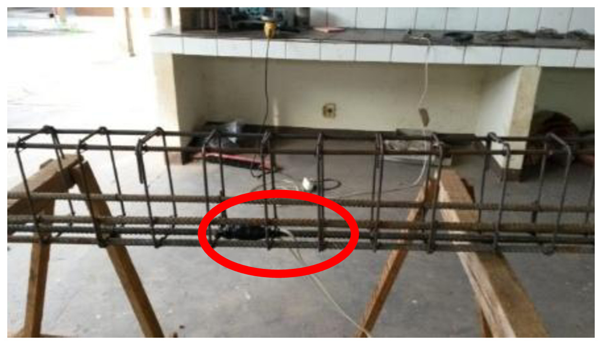
The beams were tested to determine the maximum load-bearing capacity of each material under stress, with the central load applied specifically to induce shear failure rather than bending. To monitor tensile behavior, two (02) strain gauge units were affixed to opposite faces of the central bottom rebar in each beam. This location corresponds to the region of maximum tensile stress. The reinforcement was dimensioned to remain below its yield strength, thereby preventing flexural failure and ensuring that shear governed the failure mode (Figure 5).

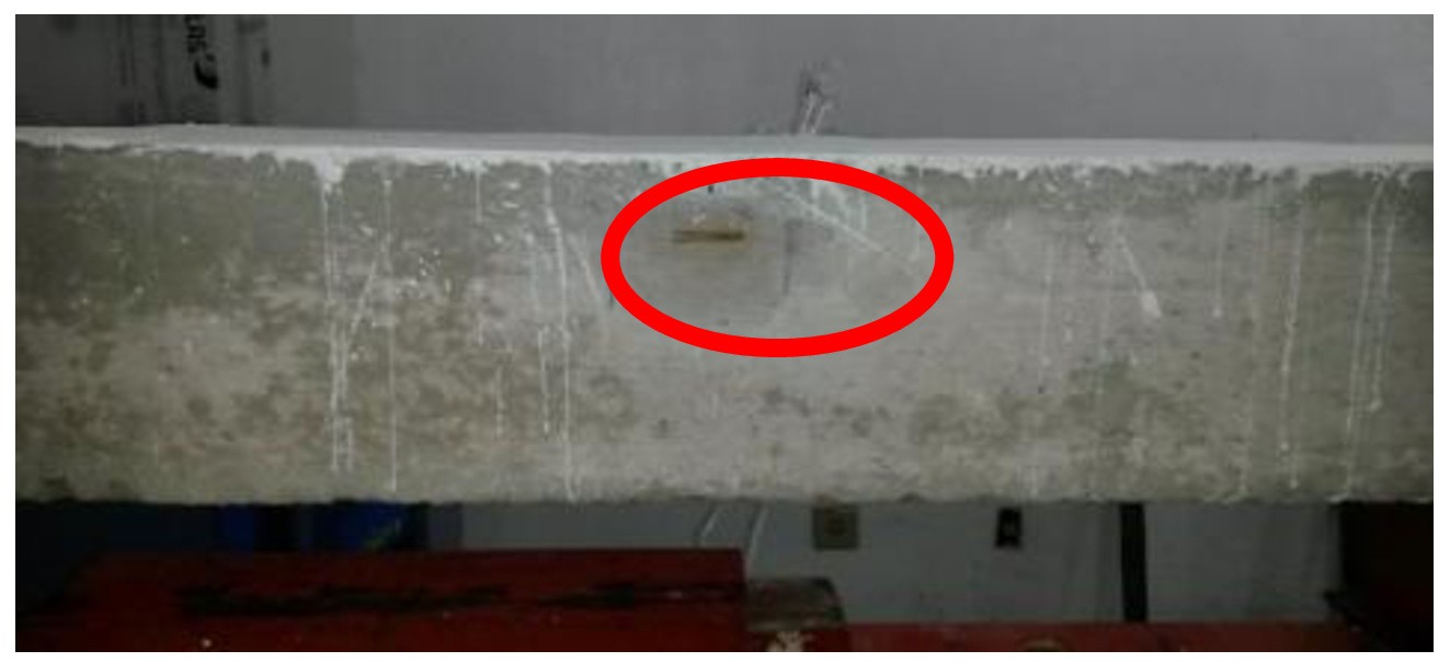
For concrete analysis, two (02) internal strain gauge units were installed in the upper central region of each beam, positioned three (3) cm below the upper longitudinal reinforcement. These gauges were used to measure the maximum compressive strain experienced by the beams during testing (Figure 6). Additionally, one (01) external strain gauge unit was mounted on a side face of each beam, located two (2) cm below the top surface. This setup allowed for monitoring crack formation on the concrete surface, thereby enhancing the effectiveness of the instrumentation system (Figure 7).

3.2.5 Testing system model
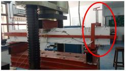
The testing setup used to induce failure in the specimens investigated in this study was based on methodologies previously applied in research conducted at the Civil Engineering Laboratory (LEC) of the Tucuruí Campus – CAMTUC – UFPA [28]. The system included three stacked steel plates, each measuring 70 mm in height and 15 mm in thickness, positioned at the center of the press table to ensure uniform load application (Figure 8).

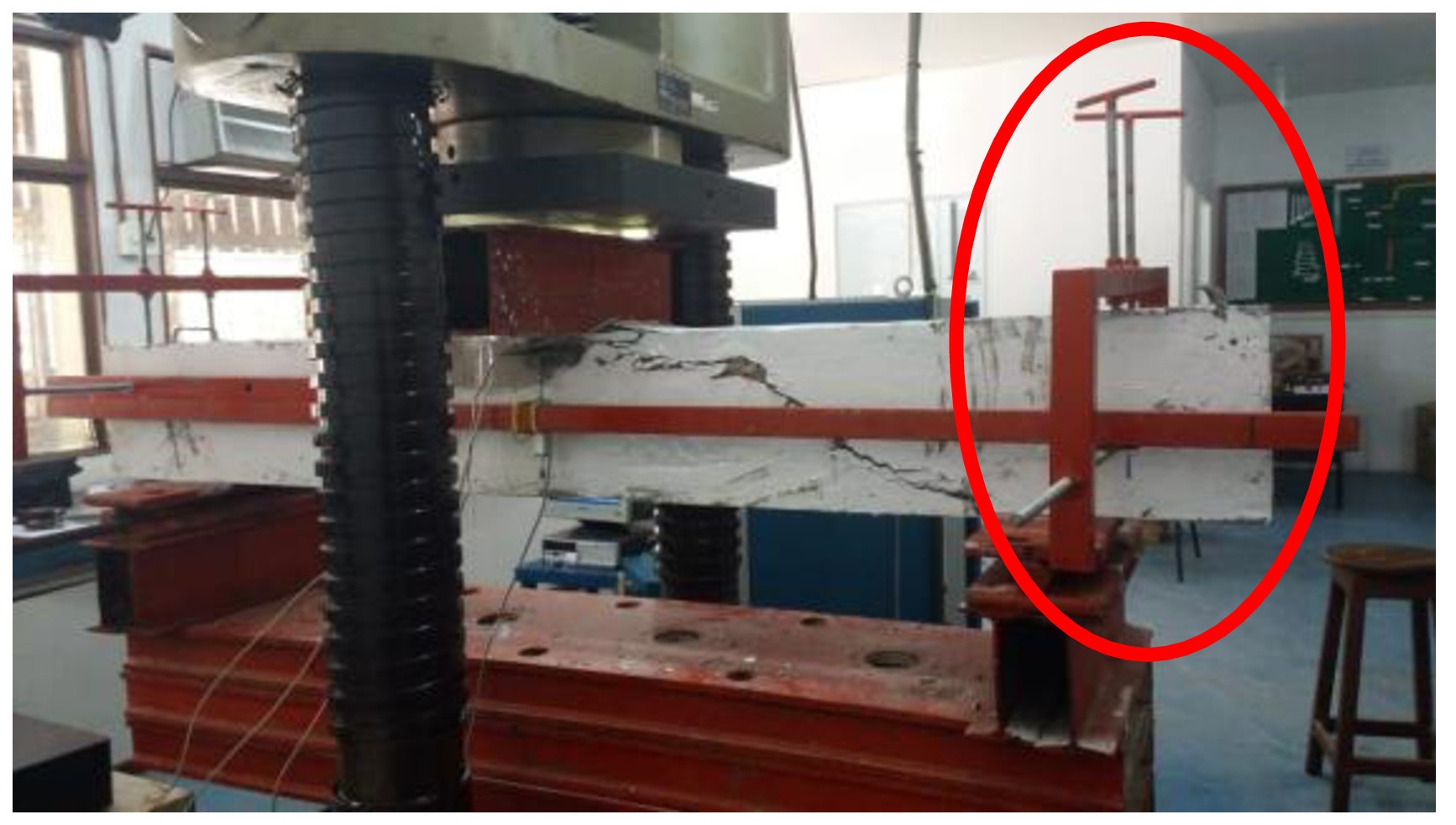
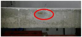
A steel 'I' profile (150 mm wide × 150 mm high × 4 mm thick) was placed at each end of the top plate. On top of each profile, two steel plates (150 mm wide × 10 mm thick) were positioned, with a 4 mm diameter roller placed between them—one allowing horizontal displacement (simulating a first-level support) and the other restricting it (simulating a second-level support). After positioning the beam on this assembly, another 'I' profile—identical in dimensions—was placed at the center of the beam to apply the load through the press, ensuring the shear span was consistent with the test design (Figure 6). The average loading rate was 0.2 kN/second. To capture displacement data, linear variable displacement transducers (LVDTs) were installed as shown in Figure 9 (yoke positioning) and Figure 10 (LVDT placement). Internal and external strain gauges—attached to both steel reinforcement and concrete—were connected via cables to the ADS 2000, a data acquisition module manufactured by Lynx Tecnologia.

3.3 Fresh concrete tests
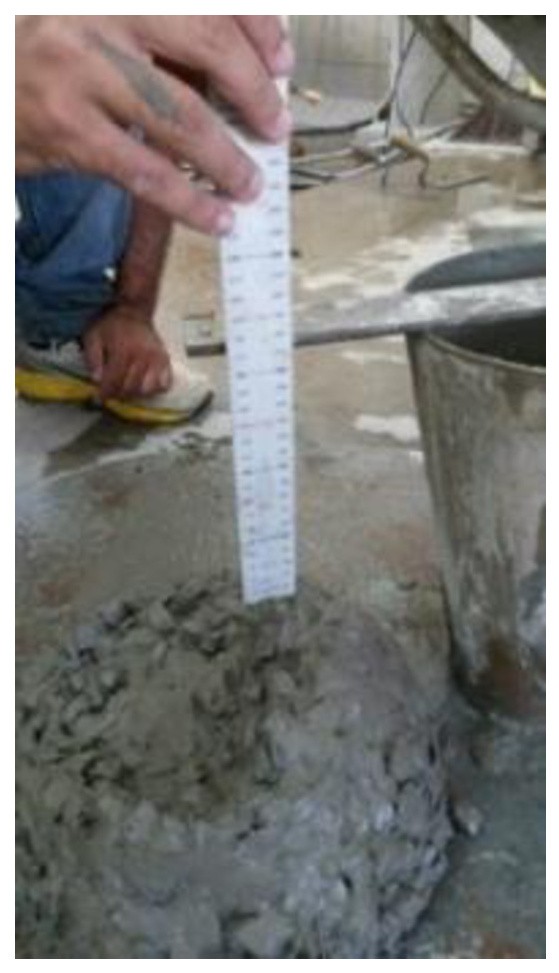
The concrete used for casting all beams was prepared at the Civil Engineering Laboratory (LEC). A total of approximately 260.74 kg was required to produce the beams and test specimens. The mix was designed to achieve a compressive strength between 25 MPa and 30 MPa at 28 days, with a cone trunk slump of 16 ± 2 cm. This slump value was selected to compensate for the anticipated loss of workability due to fiber incorporation. The slump test was conducted immediately after mixing to verify the consistency of the concrete, and the results met the specifications recommended by ABNT NBR 7222 [24], confirming its suitability for the experimental procedures (Figure 11) [26].

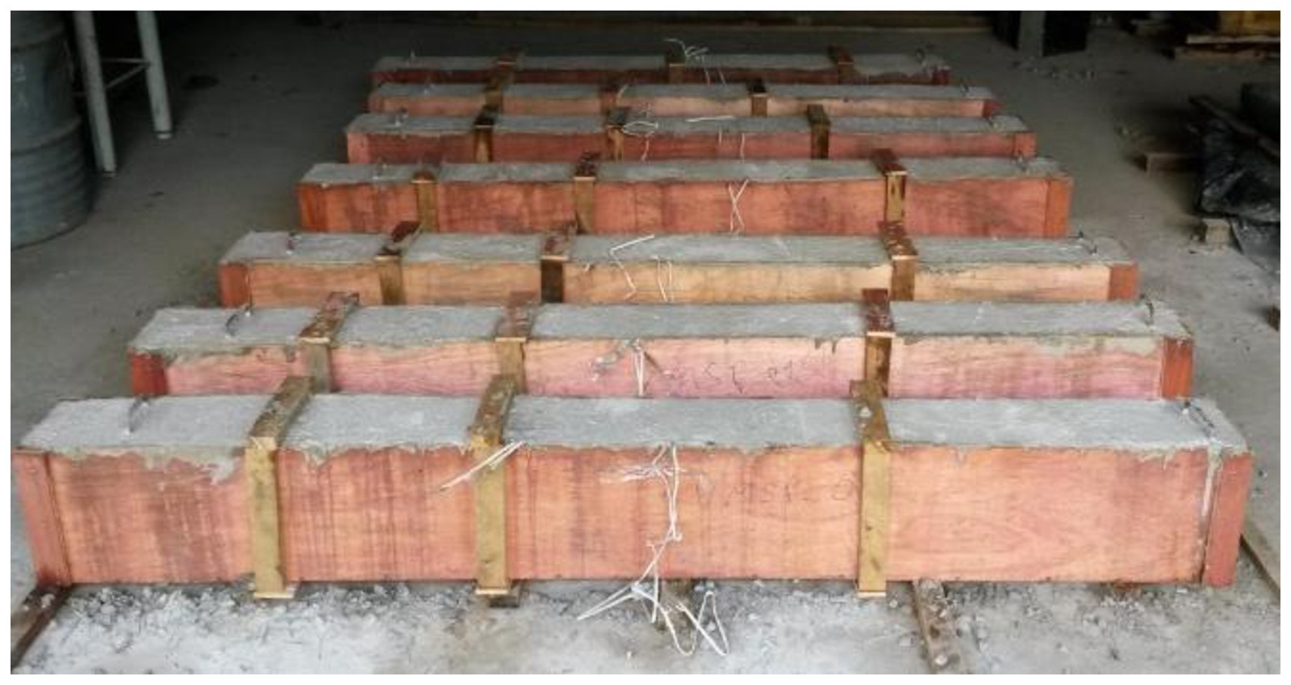
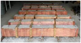
During the casting process, concrete was manually compacted for the first three beams—the reference beam and the two beams containing microglass fibers—due to the unavailability of a functioning vibrator at the Civil Engineering Laboratory (LEC). For the remaining beams—including the third beam with microglass fibers, three beams with polyester microfibers, and six beams with macrofibers (three with polypropylene and three with polyethylene)—concrete densification was performed using a needle-type mechanical vibrator provided by ConcreNorte, in accordance with the procedure outlined in ABNT NBR 6892 [29]. Figures 12 and 13 illustrate the beams after casting and curing, respectively.

As for the test specimens, concrete densification was performed manually due to the unavailability of a vibrator—similar to the procedure adopted for the first three (03) beams. For the remaining specimens, manual compaction was also chosen, as the available needle-type vibrator was too large for the molds. Additionally, standardization issues related to the casting process of the specimens were addressed, as illustrated in Figure 14 and in accordance with the guidelines established by ABNT NBR 5738 [25].

3.4 Hardened concrete and steel tests
3.4.1 Mechanical properties of concrete
To determine the mechanical properties of the concrete, cylindrical test specimens were cast in accordance with the procedures and recommendations outlined in ABNT NBR 5738 [25].
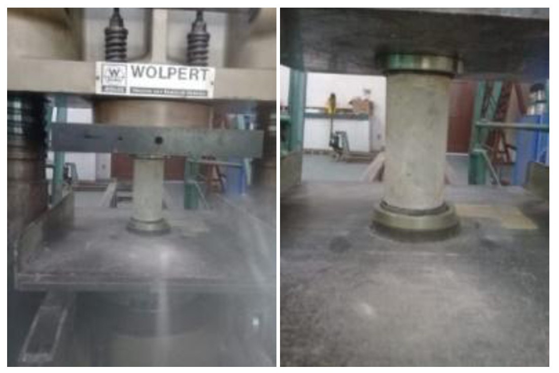
The first test performed was axial compression, following the guidelines of ABNT NBR 5739 [23], using specimens with dimensions of 100 mm in diameter and 200 mm in height (Figure 15).

The second test—diametral compression (Brazilian tensile test)—was conducted using specimens of the same dimensions, in accordance with the recommendations of ABNT NBR 7222 [24] (Figure 16).

The third test evaluated the modulus of elasticity of the concrete, also using specimens of identical dimensions, following the procedures specified in ABNT NBR 8522 [30] (Figure 17).

To characterize the mechanical properties of the concrete, between two (02) and four (04) specimens were tested for compressive strength, two (02) or three (03) for diametral tensile strength, and three (03) to eight (08) for modulus of elasticity. The results adopted correspond to the average values obtained from all specimens tested.
The following average values were recorded: 39.89 MPa for compressive strength, 4.24 MPa for tensile strength, and 32.77 GPa for modulus of elasticity, with respective standard deviations of 4.85, 0.57, and 2.76.
This approach—based on the average performance of all specimens—was adopted to reduce result dispersion, considering that each beam was produced with a distinct concrete mix. In total, 13 different mixtures were used: one (01) reference mix without fibers, six (06) mixes incorporating macrofibers (three with polypropylene and three with polyethylene), and six (06) mixes with microfibers (three with fiberglass and three with polyester). All specimens underwent testing after 28 days of curing, as presented in Table 8.
3.4.2 Mechanical properties of steel
To determine the mechanical properties of the steel used in the test specimens, three (03) samples measuring 600 mm in length were extracted for each bar diameter. The first set corresponded to the longitudinal reinforcement bars (12.5 mm in diameter), used for flexural resistance, and the second set to the transverse reinforcement bars, used for shear resistance, in accordance with the recommendations of ABNT NBR 6892 [29].
However, it was not possible to test the stirrups, as the LEC press could not accommodate the smaller diameter bars (5.0 mm), which were below the clamping capacity of the equipment.
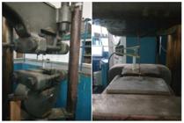
The longitudinal bars were subjected to tensile testing using the LEC press, as illustrated in Figure 18. The stress–strain curves obtained from the tested samples are presented in Figure 19, and the average values are summarized in Table 9.

4 RESULTS AND DISCUSSIONS
4.1 Comparative analysis of the results
4.1.1 Vertical displacement
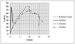
According to Figures 20 and 21, the maximum shear force (V) attained by the beams was similar across specimens. However, the vertical displacement at mid-span (δ) was notably higher in beams VFSP02, VFSP03, and VFP03. This increased displacement indicates enhanced strength and ductility, likely attributed to a higher fiber content in these beams. Post-peak behavior was also monitored to assess structural performance beyond maximum load capacity. The results demonstrate that fiber incorporation significantly improved ductility, with some beams achieving displacements up to 474% greater than the reference beam.

With regard to the microfibers shown in Figures 22 and 23, the maximum shear force (V) of beams VFPO01, VFPO03, and VFV02 was lower than that of the reference beam (VR). This suggests that, for low-modulus fibers to contribute effectively to reinforcement, a high fiber content in the matrix is required. However, these beams had a low fiber content and exhibited no greater strain than VR, which aligns with the common understanding that such fibers offer limited post-cracking reinforcement capacity [7]. For VFV03, the maximum shear was approximately equal to that of VR. In contrast, beams VFPO02 and VFV01 exhibited higher shear values than VR, and their matrices were observed to have a high fiber content. Under high tensile stress, the fibers in these beams generated significant strain, resulting in wider crack openings and clearly demonstrating post-cracking reinforcement capacity [7].


Regarding the vertical displacement at mid-span (δ), beams VFPO01, VFPO02, VFPO03, VFV01, and VFV02 exhibited values similar to that of the reference beam (VR). However, VFV03 presented significantly higher displacement than all other specimens. This indicates superior strength and ductility, which can be attributed to the higher fiber content in VFV03, despite its fibers having smaller diameters compared to VFPO03, which contains the same fiber percentage but with larger diameters. Consequently, VFV03 demonstrated enhanced post-peak and post-cracking behavior, reaching a shear strength of approximately 70 kN. Its increased load-bearing capacity, higher toughness, improved post-peak ductility, and greater residual strength were evident when compared to the reference beam [31].
4.1.2 Strain in concrete
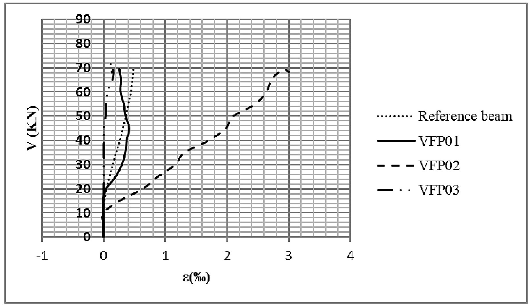
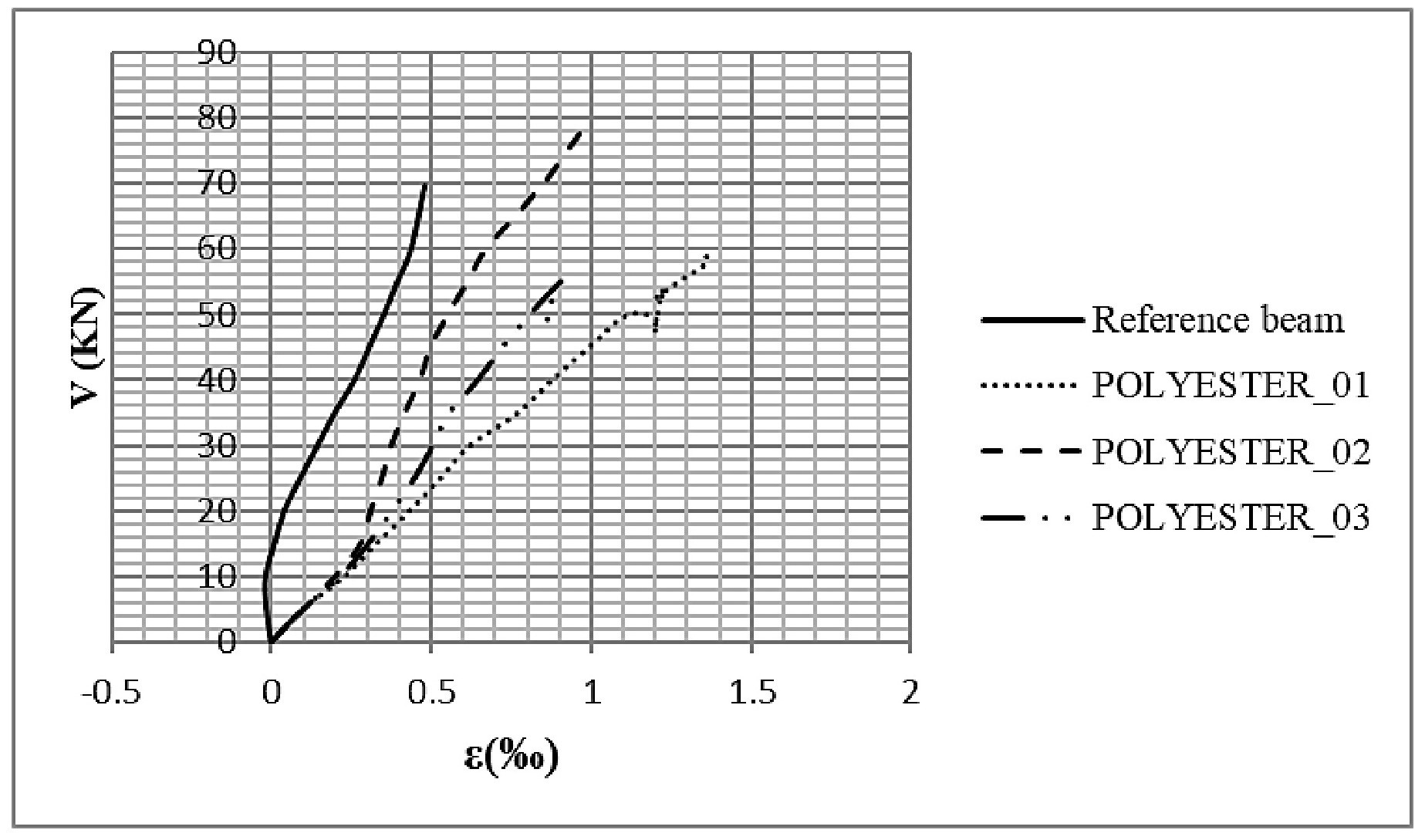
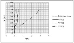
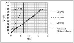
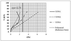
In reference to Figures 24 and 25, which present the shear force (V) versus concrete strain (ε‰) chart, beams VFSP01, VFSP02, and VFP02 exhibited concrete strain values ranging from 1.0‰ to 3.0‰, while all other beams showed lower strain levels. Notably, beam VFP02, which contained polypropylene fibers, achieved the highest strain value among all specimens, reaching 3.0%0.

According to Figures 26 and 27, beam VFV03 outperformed all other specimens in terms of concrete strain, reaching values slightly above 1.8‰. Furthermore, during the post-peak or post-cracking phase, the high fiber content in VFV03 acted effectively as a barrier to crack propagation. From the perspective of structural safety and casting performance, this behavior is particularly significant for studies focused on the incorporation of fibers in structural concrete.


Regarding the beams reinforced with polyester microfibers, VFPO02 exhibited a maximum shear force (V) greater than that of VFPO01 and VFPO03. From the standpoint of structural safety, casting efficiency, and cost-effectiveness, VFPO02 demonstrated highly favorable performance, reaching the highest shear strength of approximately 80 kN and a concrete strain of 1.0% - surpassing both the polyester-reinforced and reference beams (VR). It is also noteworthy that, from the viewpoint of concrete strain (ε‰), VFPO01 achieved a concrete strain close to 1.4%0 representing the highest strain among the polyester-reinforced beams and the second-best overall, alongside VFV02.
Therefore, the choice between VFV03 and VFPO02 depends on the specific requirements of the structural design. If the priority is higher shear strength combined with satisfactory concrete strain, VFPO02 is the preferred option. Conversely, if enhanced post-cracking behavior along with substantial shear strength is desired, VFV03 is more suitable. This highlights that all beams incorporating polyester and glass microfibers demonstrated advantages over the reference beam (VR), whether through increased shear strength, improved post-peak performance with greater concrete strain and displacement, or a combination of both characteristics.
4.1.3 Strain in bending reinforcement
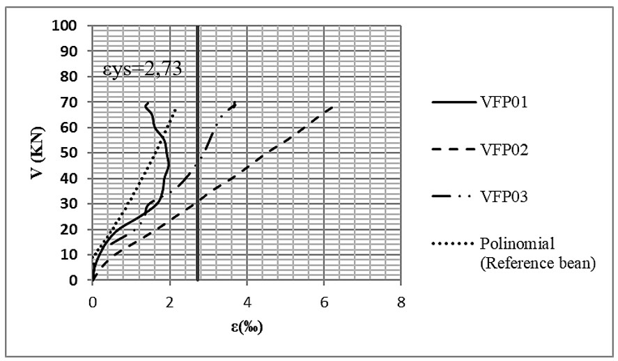
According to the results presented in Figures 28, 29, 30, and 31, the shear force (V) versus bending reinforcement strain (ε‰) chart indicates that nearly all fiber-reinforced beams exhibited yielding of the reinforcement after reaching their maximum strength capacity. The exception was beam VFP01, which did not display similar behavior due to its low fiber content. As observed in studies involving steel fibers [28], the increase in ductility resulting from higher strain levels is a notable effect of fiber incorporation. This is attributed to the ability of fibers to enhance post-cracking tensile and flexural capacity, as well as to control crack width in concrete elements [11].


4.2 Cracking and failure mode maps
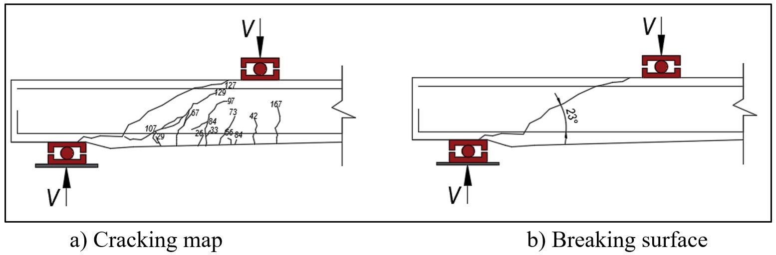
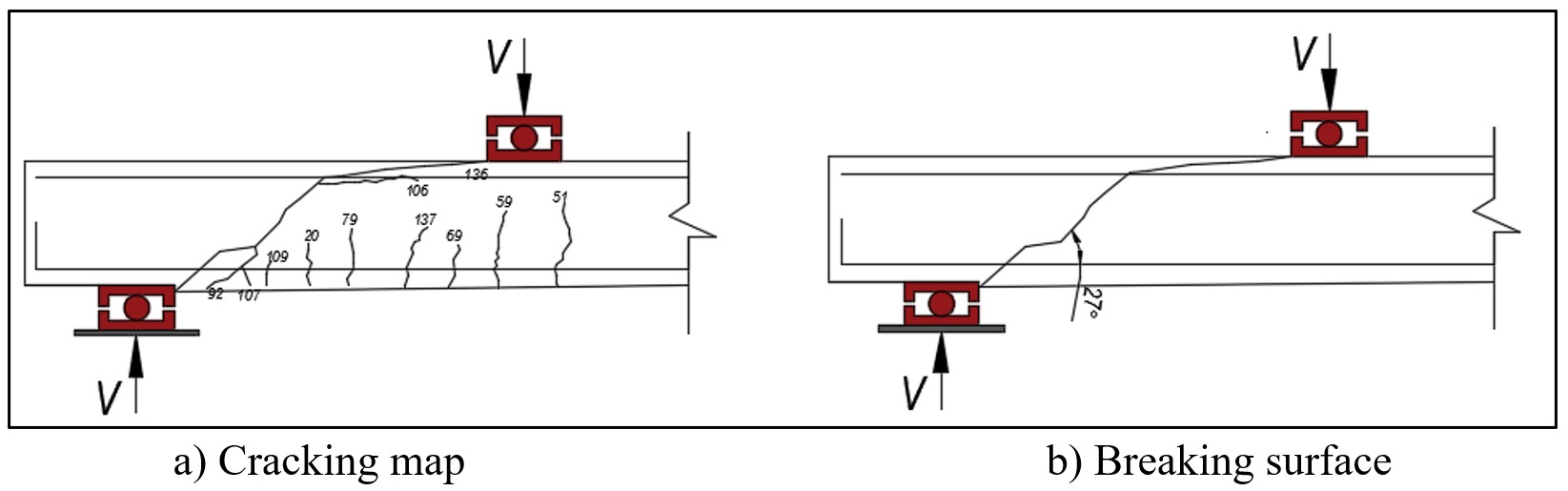
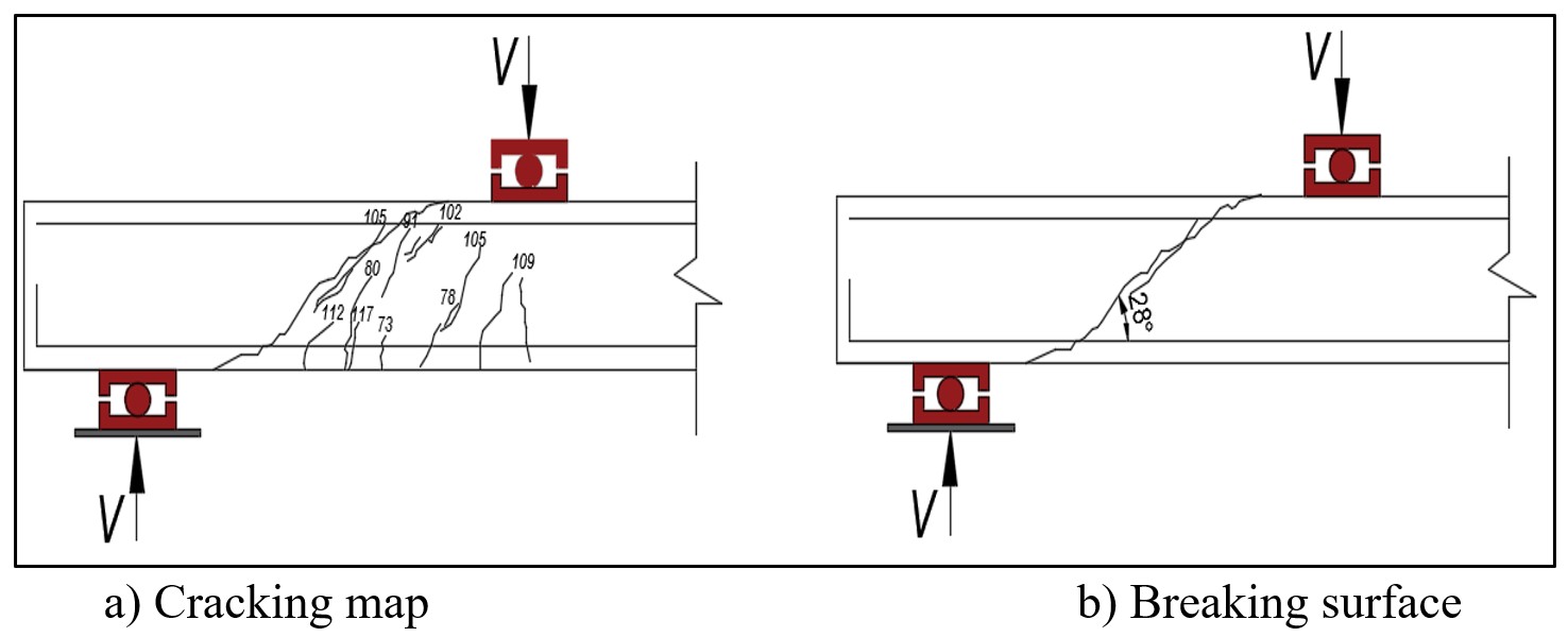
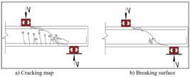
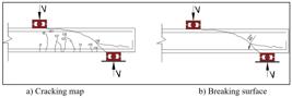
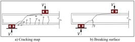
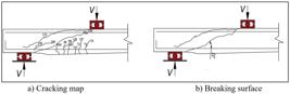
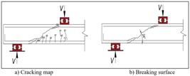
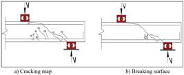
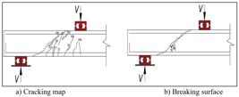
Figures 32 to 44 illustrate the post-failure or post-cracking conditions of the beams tested throughout the complete series. All specimens failed by shear, with rupture occurring in the absence of stirrups—specifically due to diagonal tension. This type of failure typically arises shortly after the formation of flexural cracks, which manifest as angled cracks in the intermediate regions between the supports and the mid-span. These cracks result from diagonal tensile stresses that exceed the tensile strength of the concrete. It is important to emphasize that, in prestressed beams, the occurrence of such cracking leads to abrupt failure due to the combined action of bending and shear forces [32].






4.3 Failure loads of the elements
Table 10 summarizes the maximum strengths achieved by the tested elements following the incorporation of macrofibers and microfibers into the concrete. In terms of failure loads, beams containing fibers achieved strengths ranging from 70 kN to 79 kN, while the reference beam reached a maximum load of 69.5 kN. This indicates a modest increase in strength following fiber addition. Specifically, the beam with polypropylene fibers (VFP02) exhibited a strength gain of 2.88%, as indicated by the Vu/Vref ratio—likely due to the low fiber content used. In contrast, the beam with polyethylene fibers (VFSP02) achieved a 13.67% increase in strength. The VFSP03 beam, however, showed a reduction in strength, which may be attributed to issues during the concreting process, such as inadequate compaction or densification.
The beams reinforced with fiberglass and polyester microfibers exhibited strength values ranging from 52.5 kN to 84.5 kN, whereas the reference beam reached a maximum load of 69.5 kN. These results indicate a strength gain resulting from the incorporation of fibers into the concrete matrix. It was observed that the addition of fiberglass fibers led to a reduction in strength gain. Specifically, as the percentage of fiberglass increased, the shear strength (Vu) of the beams decreased. Beam VFV02 exhibited a significant drop in strength (63 kN) compared to VFV01 (80 kN) and VFV03 (70 kN), likely due to issues related to manual concrete densification. The Vu/Vref ratio declined as fiber content increased, indicating that VFV01 achieved the most favorable strength gain among the beams reinforced with microfiberglass.
For beams incorporating polyester microfibers, a significant increase in ultimate shear strength (Vu) was observed as the fiber content increased. However, beam VFP01 (59.5 kN) exhibited a reduction in strength, likely due to inadequate concrete densification. Similarly, VFPO03 (52.5 kN) showed a decrease in Vu, which can be attributed to the excessive fiber content that hindered proper casting. Even with the use of mechanical densification, the concrete mix lacked complete and efficient homogeneity, compromising its structural performance.
Therefore, despite the concrete casting issues observed in beams VFV02 and VFPO01, as well as the high fiber content in VFPO03, it can be inferred that the incorporation of fiberglass in beams VFV01 and VFV03, and polyester fibers in VFPO02, contributed positively when compared to the reference beam (VR). These fiber-reinforced elements demonstrated a closer approximation to the flexural strength of the reference beam, indicating a meaningful contribution of the fibers employed in this study to the mechanical performance of the concrete.
5 CONCLUSIONS
Based on the results of the beam failure tests, the application of polypropylene and polyethylene fiber mass contents was evaluated. Possibly due to their low modulus of elasticity, the applied percentages of these fibers had little effect on increasing the shear strength of the elements. However, the fiber content in beams VFSP02, VFSP03, and VFP03 contributed to greater vertical displacement compared to the others, indicating enhanced material ductility. The results of the failure tests on beams reinforced with fiberglass and polyester fibers showed increased strength and modulus compared to the plain cement matrix, thereby contributing to enhanced shear strength in the structural elements. Specifically, there was a 15.1% gain in shear strength for beam VFV01 compared to VR, and a 21.6% gain for VFPO02 relative to VR.
Regarding the percentage contribution of each fiber type to the shear strength improvement, it was observed that the concrete exhibited greater strain capacity, allowing the flexural reinforcement to engage more effectively and reach yielding—ultimately contributing to the observed strength gains. This reinforces the conclusion that, in all tested beams, the concrete strain reached the yield point of the flexural reinforcement. Another observation was that all beams incorporating fiberglass and polyester microfibers contributed to post-peak or post-cracking stability. This is because the fibers enabled stress transfer, allowing the structural elements (the beams) to sustain a certain level of load before failing abruptly—thus acting as a warning mechanism regarding structural performance. Among the tested beams, VFV03 and VFPO01 showed the most significant contributions for their respective fiber types, with VFV03 exhibiting the greatest vertical displacement, concrete strain, and flexural reinforcement strain.
Thus, the incorporation of synthetic fibers into structural concrete can represent an efficient strategy for enhancing resistance to shear stresses, provided that several factors are carefully considered. The feasibility of this solution depends on variables such as fiber type, mechanical strength, interaction with the concrete matrix, intended reinforcement purpose, and the specific structural design. The main advantages of synthetic fibers include improved crack control and ductility, more uniform stress distribution, reduced crack propagation, ease of application, and lower weight compared to conventional reinforcements. However, the contribution to shear strength is often limited when used in isolation; synthetic fibers are typically employed as a complement to traditional reinforcement. This underscores the importance of thorough compatibility assessments with concrete, evaluation of long-term performance, and precise specification to ensure structural reliability.
Based on the data presented herein, it was concluded that the fibers used provide a degree of structural stability in the post-peak phase. After cracking occurred, the fibers enabled stress transfer between the separated regions. This contributed to controlled displacement and allowed the element to sustain a higher load compared to the reference beam before failure, thus offering a warning mechanism regarding structural performance. Therefore, this study demonstrates that fibrous reinforcement can be effectively used to control and enhance the shear performance of structural concrete. This composite material shows promise as a partial substitute for traditional transverse reinforcement—namely, stirrups in beams—by reducing the likelihood of sudden failure. Fibers such as fiberglass, polyester, polypropylene, and polyethylene contribute to increased shear strength and hardness of the concrete.
5.1 Contributions for Future Research
Although the characterization of residual tensile strength was not the primary experimental scope of this study, its critical importance for the structural behavior of fiber-reinforced concrete (FRC) is acknowledged. The ability to transfer stresses after matrix cracking defines the material’s ductility and capacity for stress redistribution. The absence of these parameters restricts the quantification of toughness; therefore, it is recommended that future investigations include flexural tests (in accordance with ASTM C1609 or EN 14651) to correlate the results presented herein with post-cracking performance.
-
Data Availability:
Research data is available in a repository.
-
Financial support:
nothing to declare
-
How to cite:
M. G. Oliveira, D. L. Sousa, M. R. Teixeira, and A. C. Gonçalves, “Shear strength evaluation of synthetic microfiber and macrofiber reinforced concrete beams,” Rev. IBRACON Estrut. Mater., vol. 19, no. 1, e19108, 2026, https://doi.org/10.1590/S1983-41952026000100008
REFERENCES
-
1 A. Medeiros, “Estudo do Comportamento à Fadiga em Compressão do Concreto com Fibras,” Ph.D. dissertation, PUC-Rio, Rio de Janeiro, 2012. https://doi.org/10.17771/PUCRio.acad.34905
» https://doi.org/10.17771/PUCRio.acad.34905 - 2 Associação Brasileira de Normas Técnicas, Projeto de Estruturas de Concreto Reforçado com Fibras – Procedimento, ABNT NBR 16935:2021, 2021.
- 3 M. di Prisco, M. Colombo, and D. Dozio, "Fibre reinforced concrete in fib Model Code 2010: principals, models and test validation," Struct. Concr., vol. 14, no. 4, pp. 342–361, 2013.
- 4 P. Pujadas, A. Blanco, S. Cavalaro, A. de la Fuente, and A. Aguado, "The need to consider flexural post-cracking creep behavior of macro-synthetic fiber reinforced concrete," Constr. Build. Mater., vol. 149, pp. 790–800, 2017.
-
5 MM Fibras para Concreto. https://mmfibras.com.br/ (accessed Jan. 4, 2018).
» https://mmfibras.com.br/ - 6 A. M. Neville and J. J. Brooks, Tecnologia do Concreto, 2a ed. São Paulo: Bookman, 2013.
- 7 A. D. Figueiredo, Concreto com Fibras de Aço (Boletim Técnico). São Paulo: Esc. Politéc., Univ. São Paulo, 2000.
- 8 A. D. Figueiredo, R. Monte and L. A. G. Bitencourt Jr., “Concreto com fibras,” in Concreto: Ciência e Tecnologia, Instituto Brasileiro do Concreto, Ed., São Paulo: Arte Interativa, 2022, v. 2, pp. 1523–1560.
- 9 B. F. Tutikian and D. D. Molin, Concreto Autoadensável, 3a ed. São Paulo: Oficina de Texto, 2021.
- 10 P. K. Mehta and P. J. M. Monteiro, Concreto: Estrutura, Propriedades e Materiais, 1a ed. São Paulo: Editora Pini, 2008.
- 11 American Concrete Institute, Guide to Design with Fiber-Reinforced Concrete, ACI 544.4R, 2018.
- 12 A. D. Figueiredo, “Concreto Reforçado com Fibras,” Ph.D. dissertation, São Paulo: Esc. Politéc., Univ. São Paulo, 2011.
-
13 I. Löfgren. “Fibre-reinforced Concrete for Industrial Construction” Göteborg: Chalmers Univ. Technol., 2005. https://www.researchgate.net/publication/257944272_Fibre-reinforced_Concrete_for_Industrial_Construction_-_a_fracture_mechanics_approach_to_material_testing_and_structural_analysis (accessed Apr. 25, 2025).
» https://www.researchgate.net/publication/257944272_Fibre-reinforced_Concrete_for_Industrial_Construction_-_a_fracture_mechanics_approach_to_material_testing_and_structural_analysis - 14 B. G. Caldas, “Estrutura Sanduíche de Matriz Poliéster Reforçado com Tecido de Sisal Conformado por Infusão a Vácuo,” M.S. thesis, Univ. Fed. Bahia, Salvador, 2014.
- 15 A. Bentur and S. Mindess, Fibre Reinforced Cementitious Composites London: Francis & Taylor, 2007.
- 16 C. M. Araújo, Reforço de Vigas de Concreto à Flexão e ao Cisalhamento com Tecidos de Fibra de Carbono Rio de Janeiro: COPPE/UFRJ, 2002.
- 17 F. R. G. Sá, “Influência da Adição de Fibras de Polipropileno no Comportamento de Elementos Estruturais de Concreto Armado com Barras de GFRP,” M.S. thesis, PUC-Rio, Rio de Janeiro, 2018.
- 18 E. J. Granato and G. Polidoro, Reforço Secundário de Proteção Mecânica sobre Impermeabilização Utilizando Macrofibra Sintética. Caçapava: Viapol, 2017.
- 19 R. V. Silva, “Microconcreto de Alto Desempenho com Fibras de Polipropileno,” M.S. thesis, Univ. Fed. Goiás, Goiânia, 2018.
- 20 Associação Brasileira de Normas Técnicas, Projeto de Estruturas de Concreto Armado com Barras de Polímero Reforçado com Fibras (FRP), ABNT NBR 17196:2025, 2025.
- 21 P. S. S. Bastos, Dimensionamento de Vigas de Concreto Armado à Força Cortante (Notas de Aula). Bauru: Universidade Estadual Paulista, 2017.
- 22 G. T. Souza, “Dosagem Experimental de Concreto Massa com Adição de Sílica Ativa Aplicado em Barragem,” M.S. thesis, Univ. Fed. Pará, Tucuruí, 2017.
- 23 Associação Brasileira de Normas Técnicas, Concreto – Ensaio de Compressão de Corpos de Prova, ABNT NBR 5739, 2007.
- 24 Associação Brasileira de Normas Técnicas, Concreto – Determinação da Resistência à Tração por Compressão Diametral de Corpos-de-Prova Cilíndricos, ABNT NBR 7222, 2011.
- 25 Associação Brasileira de Normas Técnicas, Concreto – Procedimento para Moldagem e Cura de Corpos de Prova, ABNT NBR 5738, 2015.
- 26 Associação Brasileira de Normas Técnicas, Concreto – Determinação da Consistência pelo Abatimento do Tronco de Cone, ABNT NBR NM 67, 1998.
- 27 Associação Brasileira de Normas Técnicas, Procedimento – Projeto e Execução de Estruturas de Concreto Armado, ABNT NBR 6118, 2014.
- 28 L. S. Tapajós, “Cisalhamento em Elementos de Concreto Armado com Estribos Desconectados,” M.S. thesis, Univ. Fed. Pará, Belém, 2017.
- 29 Associação Brasileira de Normas Técnicas, Materiais Metálicos – Ensaio de Tração – Método de Ensaio à Temperatura Ambiente, ABNT NBR 6892, 2013.
- 30 Associação Brasileira de Normas Técnicas, Concreto – Determinação do Módulo Estático de Elasticidade à compressão, ABNT NBR 8522, 2008.
- 31 D. A. Suk and V. Ferrari, "Aplicação do concreto reforçado com fibras de aço (FRCA) em vigas submetidas ao cisalhamento," Ambient. Constr., vol. 24, e129720, 2024, http://dx.doi.org/10.1590/s1678-86212024000100722.
- 32 M. V. Menon and I. J. Padaratz, “Reforço ao cisalhamento em vigas de concreto armado utilizando-se materiais compósitos PRFC,” Rev Eletron Eng Civ., vol. 8, pp. 32–41, 2014.
Edited by
-
Editors:
Fernando Pelisser, Leandro Mouta Trautwein
Research data is available in a repository.