Space-fed Array Variations of E-shape and U-slot cut Rectangular Microstrip Antennas using Modified Feed for Gain Enhancement
Abstract
Space-fed array comprising of E-shape or U-slot cut rectangular microstrip antennas using the modified feed designs are proposed for higher gain and wider bandwidth. Modified feed optimally illuminates the edge space-fed elements to achieve a maximum gain. Amongst the two space-fed array variations, 7 x 7 E-shape space-fed array, excited using the feed comprising of gap-coupled and stacked E-shape patches provides bandwidth and gain of 2.085 GHz (48.97%) and 18.5 dBi, respectively. The antenna exhibits broadside radiation pattern across the complete bandwidth. An experimental validation has been carried out for the simulated results that show a close agreement.
Index Terms
Broadband High gain microstrip antenna; E-shape Microstrip antenna; Spaced-fed microstrip antenna array; U-slot cut Rectangular microstrip antenna.
I. INTRODUCTION
With numerous advantages like low profile and planar configuration, microstrip antenna (MSA) finds maximum application in various types of wireless communication systems [1], [2]. For the given operating frequency, important design parameters in MSA are, bandwidth (BW), radiation pattern, polarization and gain. Wideband MSAs offering broadside radiation pattern requires polarization of the radiated field to remain un-changed across the BW. While ensuring this condition, wider BW MSA is designed either by using thicker substrate having lower dielectric constant, or by employing multi-resonator gap-coupled and stacked variation, or modified shape of the radiating patch, or the resonant slot cut designs, or MSA employing modified ground plane structures [3] - [14]. Of these, the resonant slot method is preferred since it maintains a single patch configuration. The resonant slot cut single patch wideband design offers antenna gain in the range of 5-8 dBi. To enhance the gain, antenna aperture area needs to be increased. Simplest technique to achieve the gain enhancement in addition to the BW, is the use of multi-layer gap-coupled and stacked configurations [15] - [18]. These configurations involve coaxially fed patch that is stacked with a gap-coupled configuration of additional resonators, employing cavity-backed configuration. These multi-resonator designs yield peak gain in the range of 12-13 dBi. Microstrip line series fed arrays employing non-uniform amplitude distribution across the patches are reported in [19], [20]. With thinner substrates these designs have lower BW. Using edge fed series microstrip line, array of several rectangular patches is discussed in [21]. The design is asymmetrical with respect to the positioning of the patch against the feed position, and although it offers higher gain, the effects of variation in the radiation pattern and gain against the frequencies are not presented. The gap-coupled design employing four rectangular patches on thinner substrate is presented in [22]. It employs differential feeding, shorting post and offers reflection coefficient (S11) BW of only 3%. While employing Reconfigurable Intelligent Surfaces (RIS) and Artificial Magnetic Conductor (AMC) layers over the stacked gap-coupled configurations using square patches, broadside gain of above 12 dBi is obtained [23]. However, this design is complex in implementation since it involves parasitic patches in the multiple layers. While using the concept of reflector dish antenna and further by replacing the reflecting dish with an array of microstrip patches, microstrip reflectarrays are proposed [24], [25]. The detailed study for phase compensations along the array elements for optimizing the BW is explained in [26], whereas designs employing wideband E-shape patches in the reflectarray is presented in [27]. Although the microstrip reflectarrays offer wider gain and BW, they have poor blockage efficiency, as the feed antenna is present in the path of reflecting rays from the microstrip reflector patches. This drawback of microstrip reflectarrays is removed by repositioning the feed patch so that the feed antenna does not lie in the path of radiated energy from the array patches. This led to the design of space-fed arrays [28]. Using this concept, space-fed arrays providing circular polarized [29], dual band [30] and wideband dual polarized responses are reported. As the feed is positioned below the array elements, blockage due to the feed is absent in the space-fed arrays. Hence it proves to be a better option against the microstrip reflectarrays in terms of blockage efficiency. Although wideband space-fed array is presented in [31], polarization of radiated field changes over the BW and the design requires dual feed network. Using the concept of space-fed arrays and by employing main and sub-reflectors, gain of above 20 dBi is achieved [32]. However, the requirement of a dual reflector increases the design complexities. Space-fed arrays prove to be an optimum design to achieve a higher gain, but in the reported literature, arrays that provide improvement in BW and gain supported by a linear polarized radiation pattern are missing. The fed patch governs the BW in the array, whereas gain is the function of effective illumination of the space-fed patches. Thus, there exists a research gap, which requires space-fed array configuration to offer wideband linear polarized response supported with a higher gain, while providing a less complicated design solution.
In this paper, the above research gap is addressed, and wideband high gain space-fed array designs consisting of E-shape and U-slot cut rectangular MSA (RMSA), excited using the modified feed designs, are proposed. The configurations proposed in this work are optimized using FR4 substrate (εr = 4.3, h = 1.6 mm, tan δ = 0.02) in 3 GHz frequency range. Initially, using the coaxially fed wideband E-shape MSA, different order space-fed arrays like, 1 x 3, 3 x 1, plus shape array, 3 x 3, 5 x 5, and 7 x 7, are studied for the BW and gain improvement. In each design, a detailed study to understand the effects of progressive length variations amongst the space-fed array elements and the parametric variations to study the effects of spacing of the space-fed array patches with respect to the coaxially fed E-shape MSA is carried out. The optimum results are obtained in 7 x 7 space-fed array design. It yields a simulated reflection coefficient (S11) < -10 dB BW of 1.17 GHz (30.26%) with a peak broadside gain of above 15 dBi. The enhancement in the antenna gain is achieved by modifying the feeding structure to illuminate the space-fed array elements uniformly. For this, gap-coupled stacked design of E-shape patches was considered, which increases the beam-width of the feed antenna to illuminate the edge space-fed elements. Using this feeding structure, optimum results are achieved in 7 x 7 space-fed array. It provides a simulated S11 BW of 2.085 GHz (48.97%) with a peak broadside gain of more than 18 dBi. Against the single patch fed design, gap-coupled stacked feed design yields BW improvement by 18% with 3 dBi increase in the peak gain. Similar study is carried out for space-fed array design employing U-slot cut RMSAs. The 7 x 7 space-fed array of U-slot cut RMSA excited using coaxially fed U-slot cut RMSA achieves S11 BW of 1.098 GHz (28.06%) with a peak broadside gain greater than 15 dBi. The S11 BW and gain observed in the 7 x 7 space-fed array design, while employing the feed design of gap-coupled and stacked U-slot RMSAs, are 2.429 GHz (53.2%) and 15 dBi, respectively. Thus, amongst the two slot-cut variations, the space-fed array employing E-shape MSAs yields maximum gain, while employing multi-resonator feed design.
For achieving the gain enhancement, array designs employing reflectarray or space-fed structure are selected. In space-fed array, as the feed is placed below the array elements, the blockage/obstruction for the radiated signal from array is absent and thus efficiency is improved. While employing multiple reflectors or the patch layers, increment in the gain is obtained. But these techniques are complex in design and implementation. The space-fed array designs offering wideband linear polarized response are not reported. The proposed study presents a modified gap-coupled design for the feed element that increases the feed antenna beam-width and thus helps in effective illumination of the edge space-fed patches to achieve the maximum gain. The selection of wideband E-shape patches and their gap-coupled variants adds to the S11 BW. Thus, by using the modified feed design, wideband and higher gain space-fed antenna array is realized that offer linear polarized response. The selection of modified feed as against the reported techniques of multiple reflector/multiple patch layers yields a simple configuration from the fabrication perspective. These are the technical novelties in the proposed designs as compared with the reported configurations. A tabular comparison for the proposed antenna against the reported design is presented further. The space-fed configurations proposed in this work are first optimized using IE3D simulations [33], followed by the experimental validations. The experimentation is carried out inside the antenna lab using instruments namely, vector network analyzer ZVH - 8, spectrum analyzer FSC 6, and signal generator SMB 100A. A good agreement is observed between the simulated and measured results.
II. SPACE-FED ARRAY DESIGNS USING E-SHAPE PATCHES
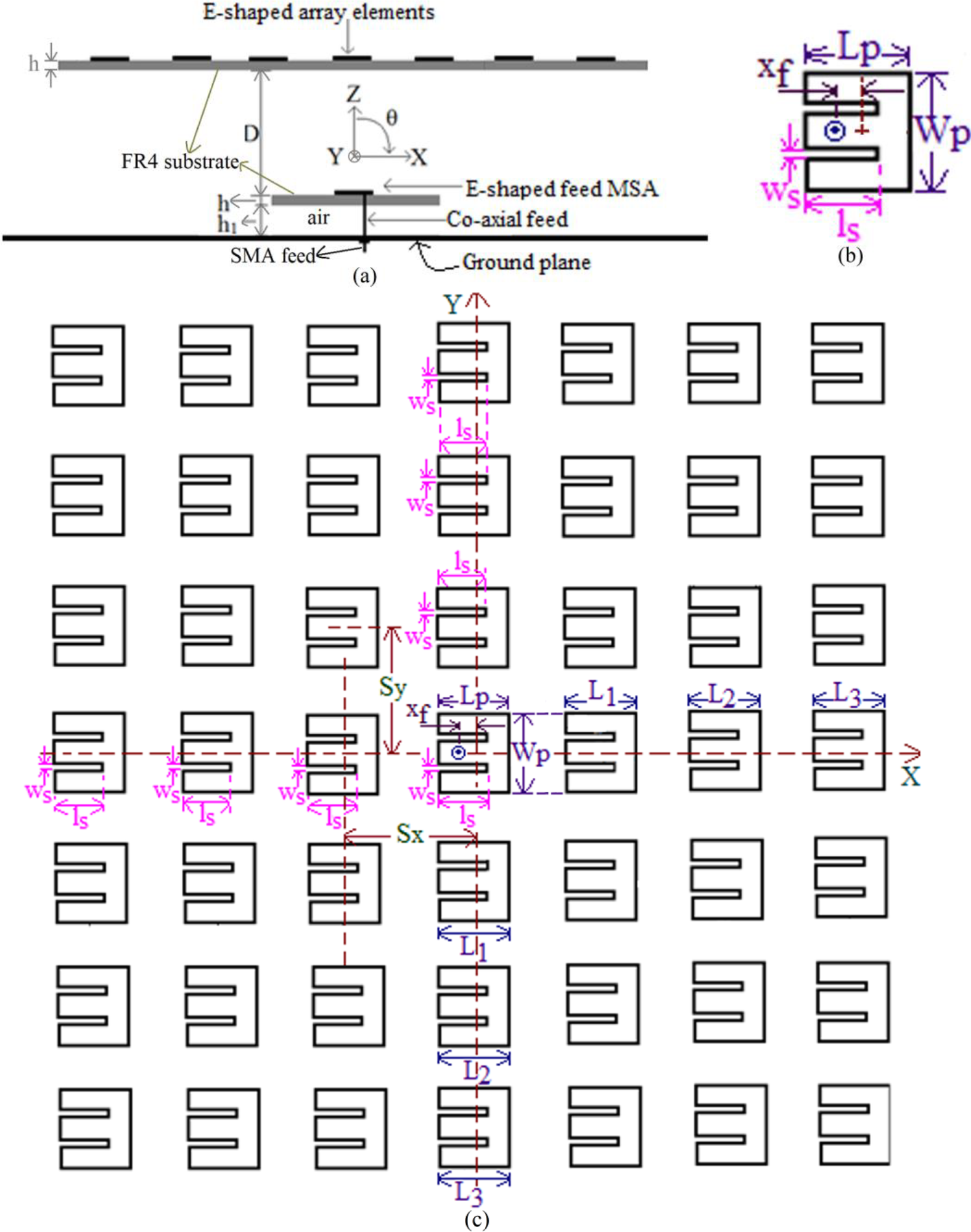
The space-fed array consisting of E-shape MSAs excited using wideband coaxially fed E-shape MSA is shown in Fig. 1(a - c). The fed and space-fed patches are fabricated on FR4 substrate. The fed patch is suspended above the ground plane using an air gap of h1 mm. Initially, fed E-shape patch is optimized for the wideband response at the fundamental mode frequency of 3.711 GHz, as shown in Fig. 1(b). As the BW optimization process for E-shape MSA is well described in the literature, it is not presented here. For substrate thickness as h = 1.6, h1 = 5 mm, fed E-shape patch dimensions as, L = 2.4, W = 2.6 cm, and pair of slot dimensions as, ls = 16, ws = 2 mm, simulated BW of 1.133 GHz (29.56%) is obtained. Antenna offers broadside radiation pattern with a peak gain of more than 6 dBi. In the feed antenna, E-plane is aligned along Φ = 00 over the BW. The units of various antenna dimensions and frequencies mentioned throughout the paper are in mm and GHz, respectively. The space-fed patches are placed on top of the coaxially fed E-shape MSA at a distance ‘D’, which realizes various array orders. In space-fed arrays, a far-field coupling exists between the coaxially fed patch and the space-fed elements [28] - [30]. With this coupling, effective antenna aperture area increases that yields gain enhancement. The elements present on space-fed layer are resonant structures [28]. In space-fed patches, there exists a path length difference from the fed patch to the space-fed patches placed exactly above, to the offset-placed patches, i.e., away from the center in the space-fed layer [28]. Due to this path length difference, there exists a phase lag for the electromagnetic energy re-radiated in the forward direction from the edge elements against that re-radiated from the center elements, in the broadside direction. To compensate for this lag, progressive tapering in patch lengths is implemented that creates a resonance frequency gradient over the space-fed aperture to maintain same phase of the re-radiated signal from all the space-fed radiators [28]. On these points, there exist a difference between FSS structures [36] - [39] against the space-fed designs.
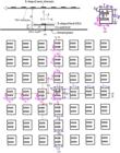
Space-fed array of E-shape MSAs excited using wideband coaxially fed E-shape MSA, (a) side view, (b) fed E-shape MSA and (c) top view of array
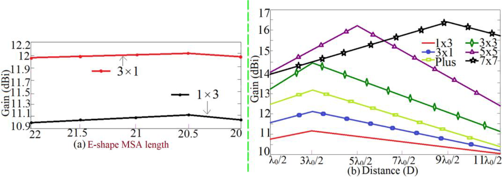
In space-fed 1 x 3 and 3 x 1 arrays, a parametric study for the variation in length L1 against Lp is carried out, and gain variation plots for the same are shown in Fig. 2(a). Through this study, effects of length tapering on gain is assessed. In 1 x 3 space-fed array, patches are present along x-axis, whereas in 3 x 1 array, space-fed patches are present along the y-axis. The length Lp is the length of top central patch in the space-fed layer, whereas adjoining patch is having a tapering in length as L1. The length of top central E-shape patch is taken to be the same as that of the fed E-shape MSA. The tapering in length depends on the order of the space-fed array. In E-shape MSA, wideband response is present around slot cut patch TM10 mode frequency [34]. As pair of slots are parallel to the surface currents at TM10 mode, they show minimal effect on the TM10 mode resonance frequency. Hence, to create the TM10 mode frequency gradient, a gradual tapering in length is applied, i.e. L1 < Lp to achieve the increasing frequencies across the space-fed patches. Using this procedure, optimum length is chosen for which the broadside gain is maximum. With the elements along y-axis, gain is found to be 1 dBi more against the design with patches along the x-axis. In the fed E-shape patch, TM10 mode is dominant in the reflection coefficient bandwidth. At this mode, beam-width in the H-plane, i.e. along y-axis is slightly higher as compared to the beam-width along the x-axis, i.e. in the E-plane [1], [34]. Due to this, excitation of the edge elements along y-axis is better as compared with the edge elements excitation along the x-axis. Because of this antenna gain is more for the space-fed elements along y-axis.
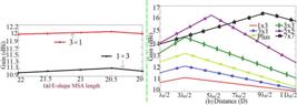
Variation in broadside gain against (a) parasitic length (in mm) tapering in space-fed layer, and (b) distance between fed patch and space-fed layer patches for various array orders
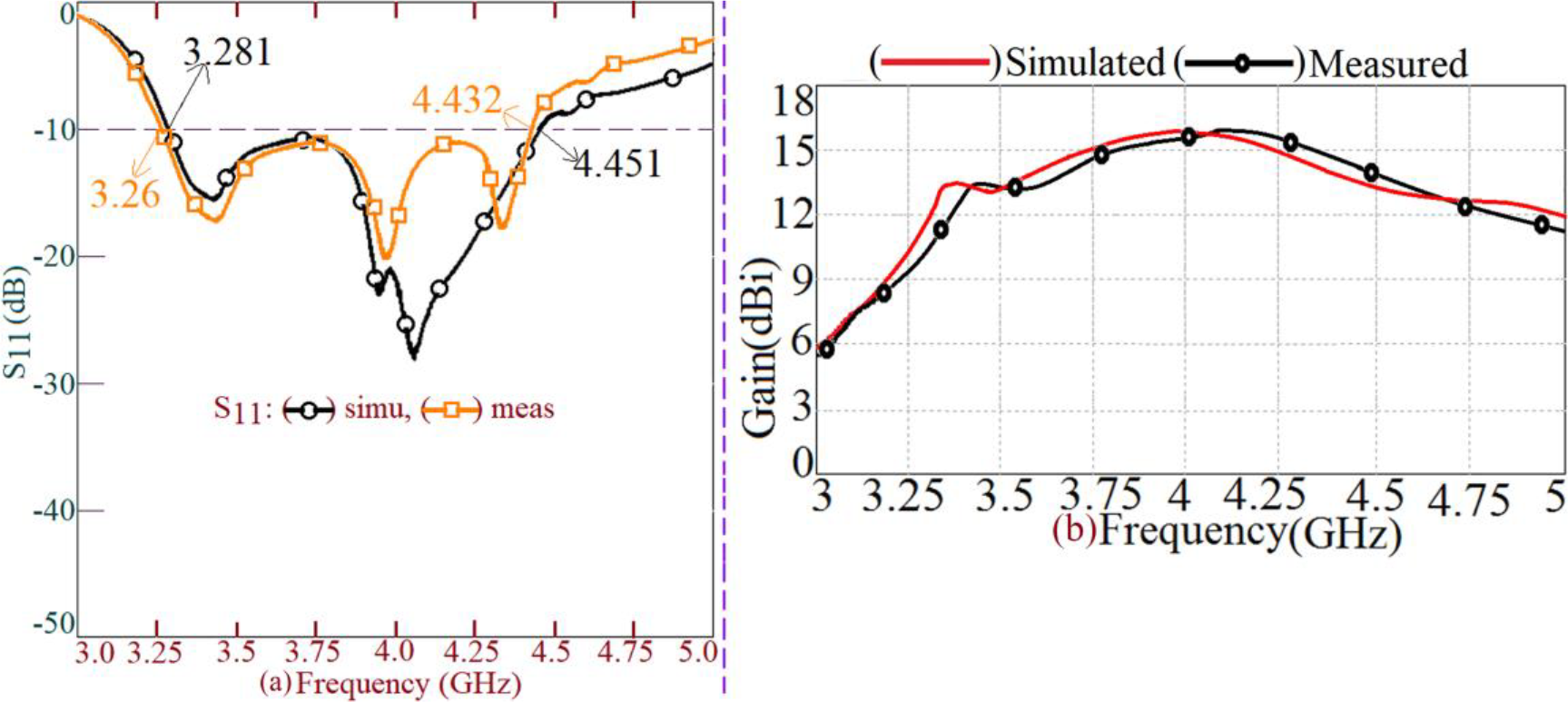
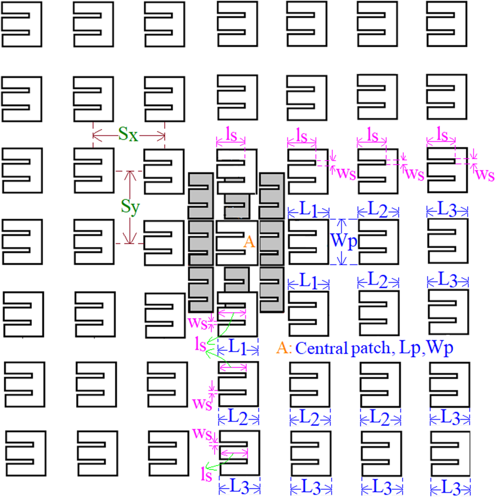
After the parametric iterations in length tapering in each order of the space-fed array, parametric study for the increment in the spacing of space-fed layer (D) with respect to the fed patch layer is carried out. An increase in D achieves an optimum illumination of the space-fed layer patches and thus achieves a maximum gain in each array order, as shown in Fig. 2(b). In larger array order, higher value of D is needed that illuminates the space-fed patches optimally. The maximum gain is resulted in 7 x 7 space-fed array design. The fed E-shape patch dimensions in this optimum space-fed array are same as that given above. The antenna dimensions in the space-fed layer are, D = 263 mm, Lp = 24, Wp = 26, L1 = 22.5, L2 = 22, L3 = 21.5 mm, and their results are shown in Fig. 3(a, b). The space-fed array gives simulated and measured S11 BW of 1.17 GHz (30.26%) and 1.172 GHz (30.47%), respectively. The antenna offers broadside peak gain of more than 15 dBi. The radiation pattern observed over the complete S11 BW is in the broadside direction with a cross-polar component of radiation lower than 15 dB as against the co-polar radiation level. As the TM10 mode is dominant over the S11 BW in E-shape patch, cross-polar radiation level in E-plane is lower than 25 dB as compared with the co-polar radiation level. The E-plane is directed along Φ = 00 across the complete BW.
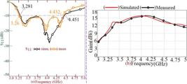
7 x 7 space-fed array excited using coaxially fed E-shape MSA; (a) S11 BW plots, (d) broadside gain variation,
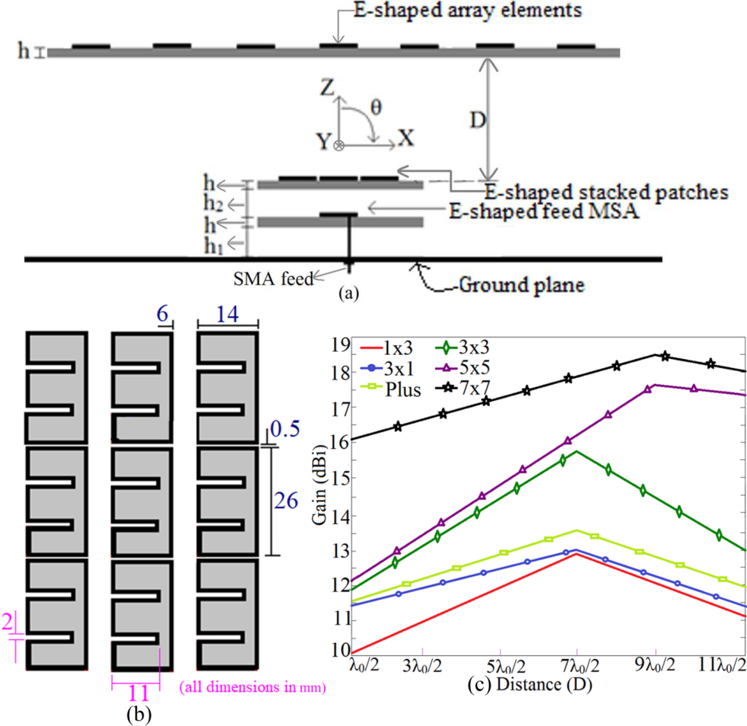
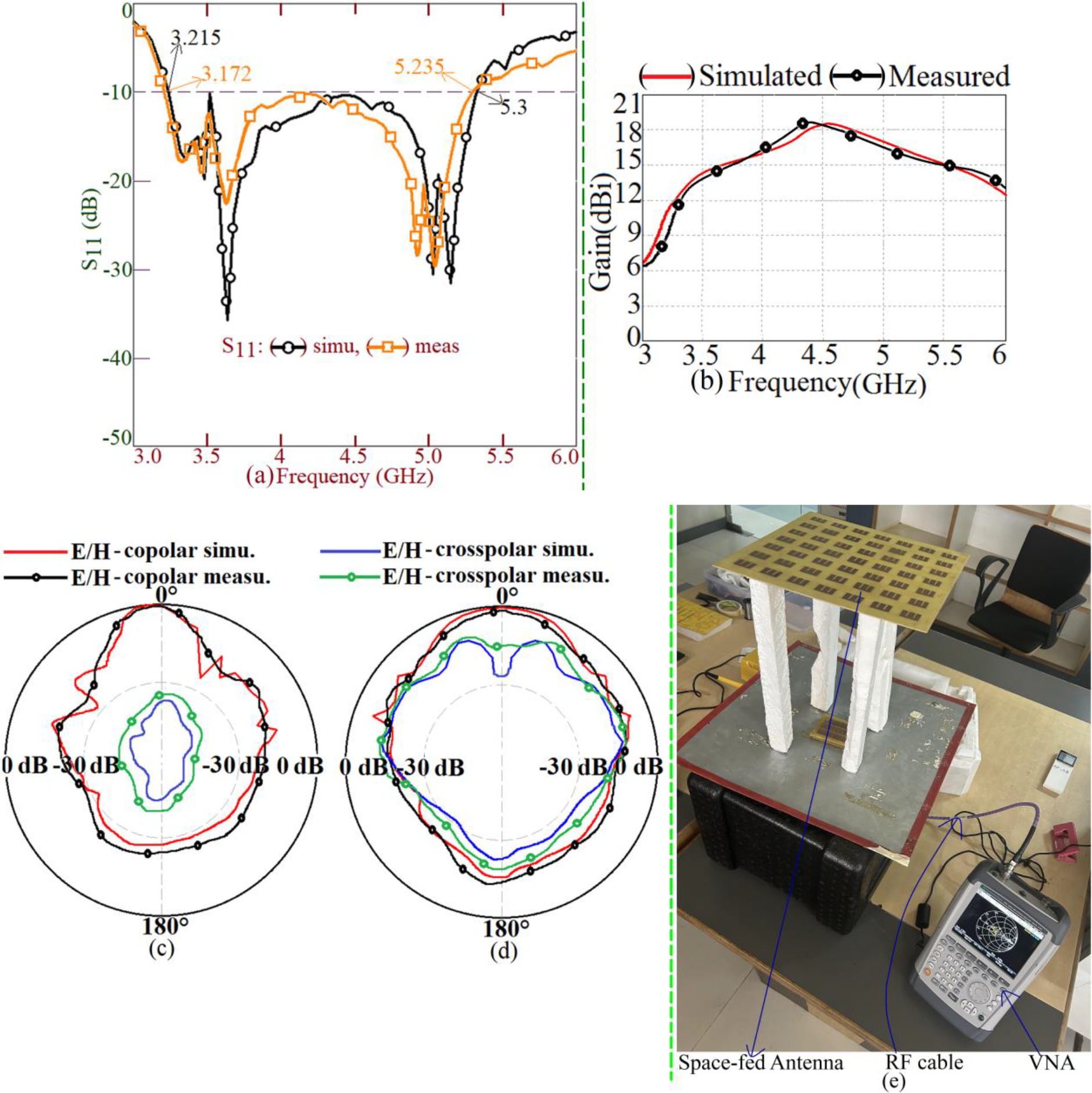
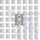
While using single E-shape patch as the feed element, optimum illumination of the edge elements in the space-fed layer as compared with the centrally located elements does not take place. To achieve the optimum illumination of edge space-fed elements, feeding area needs to be increased. For this gap-coupled stacked feed design is employed. This design achieves a wider beam-width in the radiation pattern of the fed antenna as compared with a single patch feed element that achieves an effective patch illumination. This insight led to the design of stacked gap-coupled feed consisting of E-shape patches exciting the space-fed array, as shown in Figs. 4(a, b) and 5. Initially gap-coupled stacked design of E-shape MSA as the feed element is parametrically optimized for BW. For h1 = h2 = 4 mm and for the dimensions of gap-coupled stacked E-shape MSAs as shown in Fig. 4(c), modified feed design offers simulated S11 BW of 2.123 GHz (49.60%). This feed design excites various space-fed arrays. Parametric study is carried out in each design for the progressive tapering in patch lengths and the spacing between the feed layer and space-fed array layer, to achieve the gain enhancement. The gain variation against the spacing between the space-fed and feed layer is shown in Fig. 4(c). An optimum result in terms of broadside gain is achieved in 7 x 7 space-fed design as shown in Fig. 5. For the various antenna dimensions in the 7 x 7 space-fed antenna as mentioned in the above text and figures, and for D = 339 mm, results for the optimum space-fed configuration are provided in Fig. 6(a-e). The S11 BW observed in the simulation and measurement is 2.085 GHz (48.97%) and 2.061 GHz (49.27%), respectively. With the modified feed structure, the 7 x 7 space-fed array offers broadside peak gain of larger than 18 dBi as shown in Fig. 6(b).

Space-fed E-shape MSA arrays; (a) side view and (b) modified feed design for space-fed array excited using gap-coupled stacked E-shape MSAs, its (c) gain variations against variation in D for different space-fed array orders.
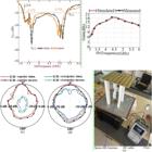
Space-fed 7 x 7 array excited using gap-coupled stacked design of coaxially fed E-shape MSAs; (a) S11 BW plots, (b) gain variation over the BW, radiation pattern at 4.3 GHz in (c) E and (d) H-planes, (e) S11 BW measurement setup.
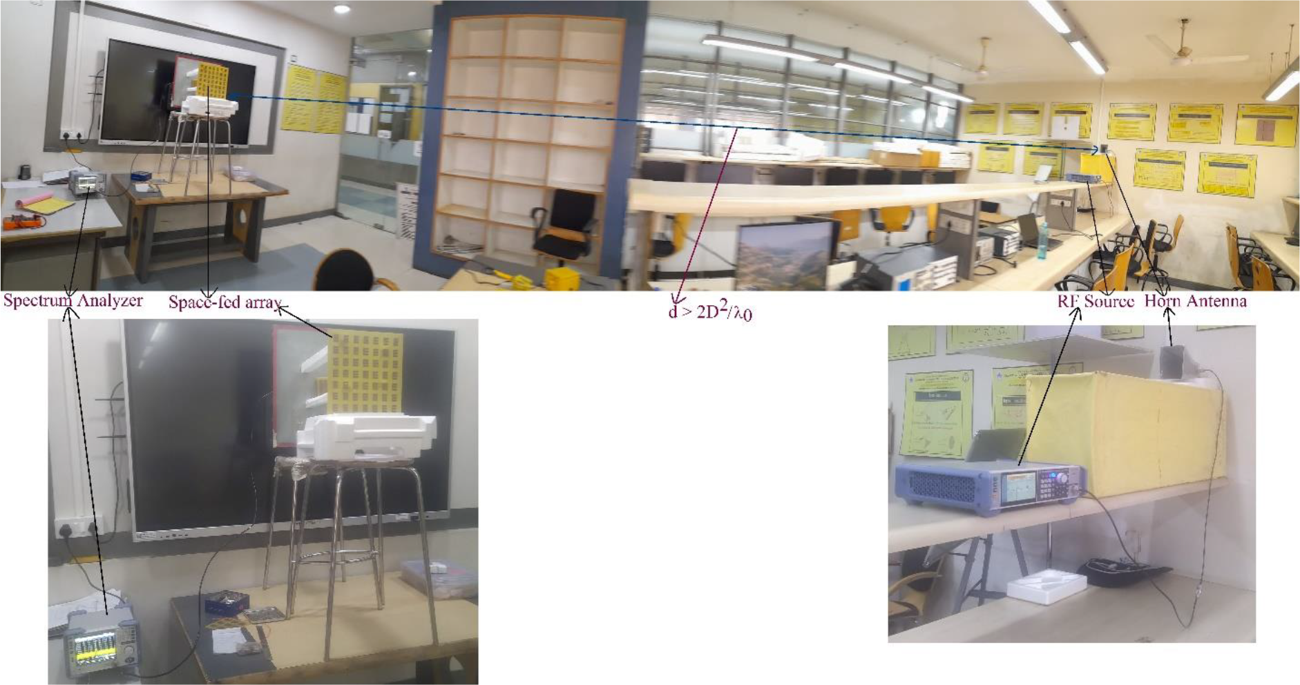
As compared with a single patch feed design, stacked gap-coupled design exciting 7 x 7 array offers 18% BW increment with 3 dBi rise in the broadside gain. The radiation pattern over the complete BW is in the broadside direction with cross-polar level less than 15 dB lower as against the co-polar radiation level as shown in Fig. 6(c, d). The E-plane remains along Φ = 00, across the BW. The antenna response is simulated and measured using square ground plane of side length 45 cm. A SMA feed connector was used to feed the antenna. The impedance BW is measured using ZVH - 8 as shown in Fig. 6(e), and radiation pattern and broadside gain are measured using FSC 6 and SMB 100A. In gain measurement, three-antenna method is used. A reference wideband high gain Horn antenna is used in the pattern and gain measurement, in which minimum far-field distance (d) is maintained between the two antennas, as mentioned in Fig. 7. With reference to the higher frequency of the BW, calculated far-field distance is large. Thus, to include the complete measurement setup in a single frame, panoramic view of the setup is provided in Fig. 7. To highlight on the same more clearly, separate photos for transmitter and receiver sections are also included in Fig. 7. The foam support was used in the measurement for the space-fed antenna. The foam has dielectric properties (εr = 1.06, tan δ = 10-6) similar to that of the air and thus it does not affect the space-fed antenna characteristics. With reference to the central measuring desk, surrounding metallic objects are absent that minimizes the electromagnetic signal reflections. The distance of surrounding wall with respect to the central measurement desk is more than 15 times the wavelength, calculated at the lowest frequency of the BW. All these details ensure minimum reflection environment for the measurement of radiation pattern and the gain inside the laboratory.

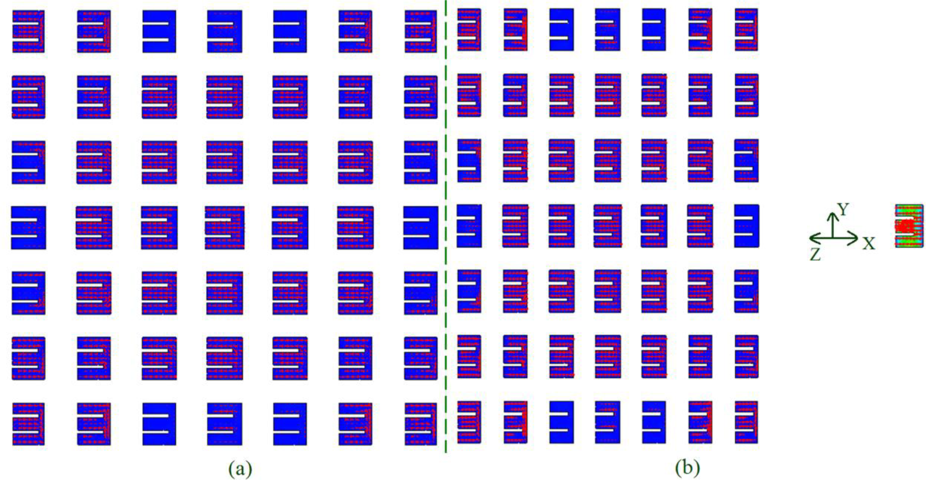
To explain the effect of modified feed design on the excitation of space-fed array, average and vector surface current distribution at the center frequency of S11 BW for the two feed variations of 7 x 7 space-fed array employing E-shape MSAs is shown in Figs. 8(a, b) and 9(a, b).

Average and vector current distribution for 7 x 7 space-fed array excited using E-shape MSA, (a) top and (b) side views
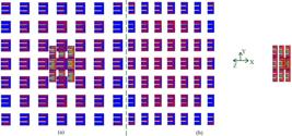
Average and vector current distribution for 7 x 7 space-fed array excited using gap-coupled and stacked E-shape MSAs, (a) top and (b) side views.
With the multi-resonator feed, feeding area exciting the space-fed elements increases. This is attributed to the wider beam-width in the gap-coupled stacked feed design. The gap-coupled stacked feed design is not optimized as array design to provide directive radiation but is used to increase the S11 BW and the beam-width so as to increase the feeding area. Thus, for the same maximum amplitude scale shown in the two feeding arrangements, gap-coupled stacked feed design strengthens the illumination of space-fed patches to increase the broadside gain.
Similar space-fed array designs were investigated using U-slot cut RMSAs. The 7 x 7 space-fed array of U-slot cut RMSA excited using coaxially fed U-slot cut RMSA achieves S11 BW of 1.098 GHz (28.06%) with a peak broadside gain greater than 15 dBi. The S11 BW and gain observed in the 7 x 7 space-fed array design, while employing the feed design of gap-coupled and stacked U-slot RMSAs, are 2.429 GHz (53.2%) and 15 dBi, respectively. In terms of broadside gain, tabular comparison against the E-shape design is presented in Table I. Amongst the two slot-cut variations, the space-fed array employing E-shape MSAs yields maximum gain, while employing multi-resonator feed design.
III. Results Discussion and Comparative Analysis
In the proposed work, wideband and high gain configurations of space-fed arrays employing E-shape and U-slot cut RMSAs are presented. Various array configurations are studied and their simulated results are summarized in Table I. With the use of modified multi-resonator feed in the form of gap-coupled stacked patches, optimum illumination of space-fed patches is achieved in E-shape patches, thus providing maximum gain of above 18 dBi in the 7 x 7 space-fed configuration. The same is not realized while using U-slot cut RMSA. This is attributed to the orthogonal surface current variations at modified TM02 mode. Both the configurations provide nearly the same BW, i.e. around 30% while using a single coaxial feed patch and nearly 50% while using a gap-coupled stacked patches as the feed. In terms of the gain and BW put together, 7 x 7 space-fed array comprising of E-shape patches excited using gap-coupled and stacked configuration offers optimum result. Thus, to present the novelty in the present space-fed array configuration, comparison of the same against the reported wideband high gain designs is presented in Table II. The comparison is presented for the technique used for achieving the wideband and high gain configurations against the realized BW and gain. Since the configurations compared are either multi-resonator gap-coupled and stacked variations or the array configurations, antenna volume is not considered for the comparison purpose, as the same is expected to be larger. The comparison stresses on the BW and gain achieved in each design.
The gap-coupled RMSA discussed in [4] offers lower gain as the same is optimized on thinner and lossy substrate. While considering the shorted gap-coupled mushroom shape structures along with coaxial feed RMSA, BW and gain achieved in the design reported in [5] is lower than the proposed configuration. The configuration discussed in [6] employs coaxially fed shorted patch with parasitic strips and rectangular patches along four edges. Inspite of multiple resonators selected in this design, BW obtained is only 20%. The modified rectangular shape MSA on thinner substrate [7] offers much lower BW and gain against the proposed 7 x 7 space-fed array. Wideband multiple slots cut RMSA discussed in [8] shows variation in broadside gain from its peak value over the BW whereas MSA discussed in [9] offers much lower S11 BW and gain. The wideband double U-slot cut RMSA discussed in [10] yields large BW and gain on thinner substrate, but it employs differential feeding and exhibit end-fire radiation pattern. The double U-slot cut RMSA discussed in [11] has a large patch area for the given antenna volume. Modified ground plane designs discussed in [12] - [14] offers large BW on thinner substrate, but they offer lower gain; attributed to a higher back-lobe radiation. The cavity backed designs employing parasitic patches in multiple layers [15] - [18], offers lower BW and gain together, against the proposed space-fed array configuration. The series fed non-uniform amplitude array designs discussed in [19], [20], offers lower BW and gain against the proposed E-shape space-fed array configuration. The series microstrip line fed MSAs discussed in [21] offers lower BW and gain. The array design presented in [23] employs 2 x 2 feeding stacked patch layers in addition to RIS and AMC layers. While employing these multiple layers in array design, BW and gain offered by the configuration is lower. The space-fed array is better option against the reflectarrays [24] - [26], as they remove the blockage efficiency. The reflect array configuration discussed in [27] employs 121 array elements and offers more than 20 dBi of gain. However, antenna efficiency (η) is only 36% in the design [27]. Also, it offers less than 10% of S11 BW. The space-fed design discussed in [29] offers large gain, but the BW is lower than 5%. The dual band space-fed design discussed in [30] has lower BW in the two operating bands. The dual feed dual polarized space-fed design discussed in [31] offers higher gain but shows lower BW. The dual reflector space-fed design discussed in [32] has large gain but offers lower BW. The FSS structures are placed near the antenna to provide the gain enhancement [36] - [39]. They provide the filtering action to enhance the antenna characteristics. Against this Space-fed designs consist of resonator patches and through the far-field coupling between the fed element and array elements, gain increment takes place.
In contrast to the reported wideband high gain designs, proposed optimum design of E-shape MSA space-fed arrays achieves BW > 50% with a peak gain of more than 18 dBi. None of the reported configurations compared above achieves both the improvements together. To enhance the antenna gain, aperture area should be increased [40]. In this work, while employing the multi-resonator gap-coupled stacked design as the feed, beam-width of the fed antenna increases, which yields optimum illumination of edge space-fed elements to increase the broadside gain. The dual reflector design does achieve the effective illumination of patches. But in contrast to the same, proposed modified feed design is simpler in fabrication. None of the reported work explains such a simple modified feed technique to obtain a higher peak gain. Therefore, modified feed design of space-fed arrays employing wideband slot cut RMSAs that achieves increment in BW and gain together through the optimum illumination of array elements, is the new contribution in the proposed study. Space-fed arrays above 7 x 7 order were also investigated. For higher order designs, present gap-coupled stacked feed does not offer gain improvement, attributed to in-ability to excite the edge elements. In higher orders, further modifications in the feed design is essential. Hence the present study is restricted to 7 x 7 order in the space-fed array.
IV. CONCLUSIONS
The space-fed array designs of wideband E-shape MSAs and U-slot cut RMSA are proposed for enhancement in the broadside gain. The gain and BW are increased by selecting the modified feed design in the form of gap-coupled stacked slot cut patches. The modified feed design offers higher beam-width in the radiation pattern, which achieves optimum illumination of edge space-fed array elements to offer gain increment along with the BW. The E-shape design offers optimum results for the BW and gain. The 7 x 7 space-fed array of E-shape patches excited using gap-coupled and stacked configurations of E-shape MSAs achieves BW of ~ 50% with a broadside gain of larger than 18 dBi. In comparison to the reported array designs, proposed configuration achieves improvement in the BW and gain together, while considering simpler modified feed configurations.
REFERENCES
- [1] G. Kumar, K. P. Ray, Broadband Microstrip Antennas, Artech house, USA, 2003.
- [2] R. Garg, P. Bhartia, I. Bahl, Microstrip Antenna Design Handbook, Artech House, London, 2001.
- [3] K. L. Wong, Compact and Broadband Microstrip Antennas, John Wiley and Sons, New York, 2002.
-
[4] K. P. Ray, V. Sevani, S. Kakatkar, “Compact broadband gap-coupled rectangular microstrip antennas”, Microwave and Optical Technology Letters, vol. 48, no. 12, pp. 2384-2389, 2006, doi.org/10.1002/mop.21976.
» https://doi.org/doi.org/10.1002/mop.21976 -
[5] Y. Cao, Y. Cai, W. Cao, B. Xi, Z. Qian, T. Wu, L. Zhu, “Broadband and High-Gain Microstrip Patch Antenna Loaded With Parasitic Mushroom-Type Structure”, IEEE Antennas and Wireless Propagation Letters, vol. 18, no. 7, pp. 1405-1409, 2019, doi: 10.1109/LAWP.2019.2917909.
» https://doi.org/10.1109/LAWP.2019.2917909. -
[6] D. Yang, H. Zhai, C. Guo, H. Li, “A compact single-layer wideband microstrip antenna with filtering performance”, IEEE Antennas and Wireless Propagation Letters, vol. 19, no. 5, pp. 801-805, 2020, doi: 10.1109/LAWP.2020.2980631.
» https://doi.org/10.1109/LAWP.2020.2980631. -
[7] J. U. Yoo, H. W. Son, “A simple compact wideband microstrip antenna consisting of three staggered patches”, IEEE Antennas and Wireless Propagation Letters, vol. 19, no. 12, pp. 2038-2042, 2020, doi: 10.1109/LAWP.2020.3021491.
» https://doi.org/10.1109/LAWP.2020.3021491. -
[8] S. K. Sharma, L. Shafai, “Performance of a Novel Ψ-shaped Microstrip Patch Antenna with Wide Bandwidth”, IEEE Antennas Wireless Propagation Letters, vol. 8, pp. 468 - 471, 2009, doi: 10.1109/LAWP.2009.2020184.
» https://doi.org/10.1109/LAWP.2009.2020184. -
[9] Y. Chen, S. Yang, Z. Nie, “Bandwidth enhancement method for low profile E-shaped microstrip patch antennas”, IEEE Transactions on Antennas and Propagation, vol. 58, no. 7, pp. 2442-2447, 2010, doi: 10.1109/TAP.2010.2048850.
» https://doi.org/10.1109/TAP.2010.2048850. -
[10] S. Radavaram, M. Pour, “Wideband radiation reconfigurable microstrip patch antenna loaded with two inverted U-slots”, IEEE Transactions on Antennas & Propagation, vol. 67, no. 3, pp. 1501-1508, 2018, doi: 10.1109/TAP.2018.2885433.
» https://doi.org/10.1109/TAP.2018.2885433. -
[11] T. Q. Fan, B. Jiang, R. Liu, J. Xiu, Y. Lin, H. Xu, “A Novel Double U-Slot Microstrip Patch Antenna Design for Low-Profile and Broad Bandwidth Applications”, IEEE Transactions on Antennas and Propagation, vol. 70, no. 4, pp. 2543-549, 2022, doi: 10.1109/TAP.2021.3125382.
» https://doi.org/10.1109/TAP.2021.3125382. -
[12] K. Mondal, P. P. Sarkar, “M-Shaped broadband Microstrip Patch Antenna with Modified Ground Plane”, Microwave and Optical Technology Letters, vol. 57, no. 6, pp. 1308-312, 2015, doi.org/10.1002/mop.29068.
» https://doi.org/doi.org/10.1002/mop.29068 -
[13] V. A. P. Chavali, A. A. Deshmukh, “Wideband Designs of Regular Shape Microstrip Antennas Using Modified Ground Plane”, Progress In Electromagnetics Research C, vol. 117, pp. 203-219, 2021, doi:10.2528/PIERC21110202.
» https://doi.org/10.2528/PIERC21110202. -
[14] S. Baudha, M. V. Yadav, “A novel design of a planar antenna with modified patch and defective ground plane for ultra-wideband applications”, Microwave and Optical Technology Letters, vol. 61, pp. 1320-1327, 2019, doi.org/10.1002/mop.31716.
» https://doi.org/doi.org/10.1002/mop.31716 -
[15] R. Chopra, G. Kumar, “High gain broadband stacked triangular microstrip antennas”, Microwave and Optical Technology Letters, vol. 62, no. 9, pp. 2881-2888, 2020, doi.org/10.1002/mop.32372.
» https://doi.org/doi.org/10.1002/mop.32372 -
[16] R. Chopra, G. Kumar, “Broadband and high gain multilayer multiresonator elliptical microstrip antenna”, IET Microwaves, Antennas & Propagation, vol. 14, no. 8, pp. 821-829, 2020, doi.org/10.1049/iet-map.2019.0186.
» https://doi.org/doi.org/10.1049/iet-map.2019.0186 -
[17] S. Wadkar, B. Hogade, R. Chopra, G. Kumar, “Broadband and high gain stacked microstrip antenna array”, Microwave and Optical Technology Letters, vol. 61, no. 7, pp. 1882-1888, 2019, doi.org/10.1002/mop.31813.
» https://doi.org/doi.org/10.1002/mop.31813 -
[18] K. Raha, K. P. Ray, “Broadband High Gain and Low Cross-Polarization Double Cavity-Backed Stacked Microstrip Antenna”, IEEE Transactions on Antennas and Propagation, vol. 70, no. 7, pp. 5902-5906, 2022, doi: 10.1109/TAP.2022.3140349.
» https://doi.org/10.1109/TAP.2022.3140349. -
[19] B. Singh, N. Sarwade, K. P. Ray, “Compact Planar Antenna Array With Tapering in Both Planes for Desired First Sidelobe Reduction”, IEEE Antennas and Wireless Propagation Letters, vol. 18, no. 3, pp. 531-535, 2019, doi: 10.1109/LAWP.2019.2896114.
» https://doi.org/10.1109/LAWP.2019.2896114. -
[20] N. Kalva, B. M. Kumar, “Feedline Design for a Series-Fed Binomial Microstrip Antenna Array With No Sidelobes”, IEEE Antennas Wireless Propagation Letters, vol. 22, no. 3, pp. 650-654, 2023, doi: 10.1109/LAWP.2022.3221662.
» https://doi.org/10.1109/LAWP.2022.3221662. -
[21] Y. Zhang, X. Y. Zhang, Y. M. Pan, “Compact Singleand Dual-Band Filtering Patch Antenna Arrays Using Novel Feeding Scheme”, IEEE Transactions on Antennas and Propagation, vol. 65, no. 8, pp. 4057-4066, 2017, doi: 10.1109/TAP.2017.2717046.
» https://doi.org/10.1109/TAP.2017.2717046. -
[22] X. Fu, Z. Zhang, J. Wang, “A Compact Frequency Scanning Planar Array Using Characteristic Mode Analysis”, IEEE Antennas and Wireless Propagation Letters, vol. 20, no. 9, pp. 1666-1670, 2021, doi: 10.1109/LAWP.2021.3092366.
» https://doi.org/10.1109/LAWP.2021.3092366. - [23] A. Rochkari, S. Verulkar, M. Trimukhe, V. Bodade, R. Gupta, “Low Profile High Gain Wideband Stacked MSA Array for 5G, WLAN and C-Band Applications”, International Journal of Microwave and Optical Technology, vol. 19, no. 1, pp. 80-88, 2024.
-
[24] D. M. Pozar, S. D. Targonski, H. D. Syrigos, “Design of Millimeter Wave Microstrip Reflectarrays”, IEEE Transactions on Antennas and Propagation, vol. 45, no. 2, pp. 287-296, 1997, doi: 10.1109/8.560348.
» https://doi.org/10.1109/8.560348. -
[25] J. Huang, R. J. Pogorzelski, “A Ka-Band Microstrip Reflectarray with Elements Having Variable Rotation Angles”, IEEE Transactions on Antennas and Propagation, vol. 46, no. 5, pp. 650-656, 1998, doi: 10.1109/8.668907.
» https://doi.org/10.1109/8.668907. -
[26] M. E. Bialkowski, K. H. Sayidmarie, “Bandwidth considerations for a Microstrip Reflectarray”, Progress In Electromagnetics Research B, vol. 3, pp. 173-187, 2008, doi:10.2528/PIERB07120405.
» https://doi.org/10.2528/PIERB07120405. -
[27] S. R. Lee, E. H. Lim, F. L. Lo, “Broadband Single-layer E-Patch Reflectarray”, RADIOENGINEERING, vol. 26, no. 1, pp. 97-106, 2017, doi:10.13164/re.2017.0097.
» https://doi.org/10.13164/re.2017.0097. -
[28] R. Bhide, G. Kumar, “Equivalence of space-fed microstrip antenna array with Horn Antenna”, Microwave and Optical Technology Letters, vol. 52, no. 5, pp. 1180-1183, 2010, doi.org/10.1002/mop.25092.
» https://doi.org/doi.org/10.1002/mop.25092 -
[29] R. Bhide, G. Kumar, “Circularly polarized space-fed microstrip antenna arrays”, Microwave and Optical Technology Letters, vol. 52, no. 10, pp. 2221-2223, 2010, doi.org/10.1002/mop.25451.
» https://doi.org/doi.org/10.1002/mop.25451 -
[30] R. Bhide, G. Kumar, “Dual band space-fed microstrip antenna arrays with orthogonal polarization”, Microwave and Optical Technology Letters, vol. 53, no. 4, pp. 793-795, 2011, doi.org/10.1002/mop.25851.
» https://doi.org/doi.org/10.1002/mop.25851 -
[31] P. K. Mishra, D. R. Jahagirdar, G. Kumar, “Broadband Dual Polarized Space-Fed Antenna Arrays with High Isolation”, Progress in Electromagnetics Research C, vol. 55, pp. 105-113, 2014, doi:10.2528/PIERC14102701.
» https://doi.org/10.2528/PIERC14102701. -
[32] G. Li, Y. Ge, Z. Chen, “A Compact Multibeam Folded Transmit array Antenna at Ku-Band”, IEEE Antennas and Wireless Propagation Letters, vol. 20, no. 5, pp. 808-812, 2021, doi: 10.1109/LAWP.2021.3064217.
» https://doi.org/10.1109/LAWP.2021.3064217. - [33] IE3D Version 12.1, Zeland Software
-
[34] A. A. Deshmukh, K. P. Ray, “Analysis of Broadband Ψ-shaped Microstrip Antennas”, IEEE Antennas and Propagation Magazine, vol. 55, no. 2, pp. 107-123, 2013, doi: 10.1109/MAP.2013.6529321.
» https://doi.org/10.1109/MAP.2013.6529321. -
[35] A. A. Deshmukh, K. P. Ray, “Analysis of Broadband Variations of U-slot cut Rectangular Microstrip Antennas”, IEEE Magazine on Antennas and Propagation, vol. 57, no. 2, pp. 181-193, 2015, doi: 10.1109/MAP.2015.2414533.
» https://doi.org/10.1109/MAP.2015.2414533. -
[36] G. D. Catton, H. G. Espinosa, A. A. Dewani, S. G. O'keefe, “Miniature Convoluted FSS for Gain Enhancement of a Multiband Antenna”, IEEE Access, vol. 9, pp. 36898-36907, 2021, doi:10.1109/ACCESS.2021.3060398.
» https://doi.org/10.1109/ACCESS.2021.3060398. -
[37] A. Swetha, K. R. Naidu, “Gain Enhancement of an UWB Antenna Based on a FSS Reflector for Broadband Applications”, Progress In Electromagnetics Research C, vol. 99, pp. 193-208, 2020, doi:10.2528/PIERC19120905.
» https://doi.org/10.2528/PIERC19120905. -
[38] N. Prasad, P. Pardhasaradhi, B. T. P. Madhav, T. Islam, S. Das, M. El Ghzaoui, “Radiation Performance Improvement of a Staircase Shaped Dual Band Printed Antenna with a Frequency Selective Surface (FSS) for Wireless Communication Applications”, Progress In Electromagnetics Research C, vol. 137, pp. 53-64, 2023, doi:10.2528/PIERC23072402.
» https://doi.org/10.2528/PIERC23072402. -
[39] W. Li, Y. Wang, S. Sun, X. Shi, “An FSS-Backed Reflection/Transmission Reconfigurable Array Antenna”, IEEE Access, vol. 8, pp. 23904 - 36907, 2020, doi:10.1109/ACCESS.2020.2970611.
» https://doi.org/10.1109/ACCESS.2020.2970611. - [40] C. A. Balanis, Antenna Theory: Analysis and Design, 3rd Edn., John Wiley and Sons, New York, USA, 2005.