Leakage Current Mitigation in On-Grid Photovoltaic Systems Using a Flexible Multi-Level Inverter Topology
ABSTRACT
Leakage current is an issue that often causes problems in transformerless grid-connected PV inverters, such as electromagnetic interference, which is conducted or radiated and derates the quality of power injected into the grid. It can also lead to electrical safety problems, impair the performance of other equipment nearby, and thus make the generation system unavailable. Therefore, mitigation procedures for the leakage current in transformerless grid-connected PV inverters are essential to ensure system efficiency and safety. In this sense, a new single-phase grid-connected transformerless inverter topology was proposed using modulation switching techniques to keep the leakage current at acceptable standard levels. With the proposed topology, by monitoring the leakage current rms value, the inverter can be driven in a three- or five-level pattern for the main switches, thereby keeping the leakage current at a satisfactory level. The topology was implemented in a versatile hardware-in-loop Typhoon-HIL to emulate a digital twin of the complete system, with the control loops and switching generation embedded in a family Texas Instruments F28335 DSP. The results obtained for total harmonic distortion and energy conversion efficiency were then compared with other consolidated topologies, and the leakage current was proved to be effectively modified when the inverter is switched in three- or five-level modes.
KEYWORDS
Leakage current; Common mode voltage; Multi-level PWM; Photovoltaic inverters
I. INTRODUCTION
In recent years, growing concern about energy demand and the substantial environmental impact caused by using fossil fuels to generate energy has led to the search for renewable energy sources. The alignment of technology and science advancements with sustainable development goals - SDG 1 of the United Nations is a paramount motor to the emerging research in several knowledge areas; cleaning, efficient and effective power conversion is adherent to the goals #7 - Affordable and Clean Energy, #9 - Industry, Innovation and Infrastructure, and #11 - Sustainable Cities and Communities, asides to indirect contributions to other SDG. In this scenario, solar energy stands out due to its clean and abundant nature, which can be competitive and work in conjunction with hydro and thermal sources [1], [2]. Due to these characteristics and the increasing development of energy conversion systems, new solutions are constantly being sought to overcome the challenges associated with photovoltaic energy conversion, such as the variation in solar irradiation and the need for high efficiency.
Various factors, such as the growth in the demand for clean energy, the reduction in the cost of power electronics, and advances in control technologies, drive the evolution of photovoltaic inverter topologies. However, new challenges arise with the increasing injection of solar energy into the electricity grid, such as the need to guarantee the stability and compatibility of the system with other renewable energy sources [3], [4]. In this context, new inverter topologies must offer greater flexibility, modularity, and intelligence, allowing photovoltaic systems to be integrated into increasingly complex and distributed electrical grids [5].
Previous work on photovoltaic inverter topologies presents diverse approaches and levels of detail. Authors such as [6] and [7] offer in-depth analyses of the main topologies, comparing their performance in terms of efficiency, cost, and waveform quality. [8] and [9], [10] explore the latest trends in modular and multilevel topologies, highlighting their advantages for large photovoltaic systems. This variety of perspectives enriches knowledge on the subject and helps develop the most suitable topologies for each application.
The function of the inverter is to convert the direct current generated by photovoltaic modules into an alternating current suitable for use in electrical distribution networks. In this context, transformerless inverters have become increasingly common due to their advantages over systems with transformers. In addition to cost and the physical volume reduction, they allow for improved energy efficiency and better conversion of the direct current generated by photovoltaic modules into alternating current for injection into the electrical grid [11].
In this way, a new topology of the inverter connected to the grid without a transformer that presents low leakage current through the modulation switching strategy allows situations where the parasitic capacitance reaches a value such that the leakage current exceeds the normative limits to ensure the continuity of power injection into the grid.
This paper is divided into six sections. The second section briefly explains the transformerless inverter and its characteristics, comparing it with the transformer-based inverter. The third section describes the most common transformerless inverter topologies in the literature, describing their principle of operation. The fourth section proposes a new topology to solve the problems addressed in the previous sections by changing levels based on the value of the relevant leakage current in the system. In section five, a comparison is made between the proposed topology and the topologies in the literature. Finally, the sixth section presents the conclusion of the results obtained in the article.
II. PROBLEMS OF TRANSFOMERLESS PV INVERTERS
Inverters transformer-based (galvanically isolated) have disadvantages over transformerless (non-isolated) inverters. One of the main disadvantages is their weight. The transformers used in these inverters are typically made of ferromagnetic material, such as silicon steel, which makes them heavy [12]. Another important disadvantage of inverters with transformers is related to the volume occupied by these components [13]. Transformers tend to take up a considerable amount of space due to the need for adequate insulation and the arrangement of the coils. It limits design flexibility in applications where space is a valuable resource. Finally, efficiency is another notable disadvantage of inverters with transformers [14]. By nature, transformers introduce losses into the system due to hysteresis effects and eddy currents. Although this, transformerless inverters have some disadvantages, including parasitic capacitance that implies in common mode voltage and leakage current, which will be explained in this section, detailing their characteristics.
A. Parasitic capacitance
The photovoltaic module is structured as: an aluminum frame, special glass, encapsulant, photovoltaic cells, encapsulant, and a back sheet. In a normative way, it is required that the metallic structures are grounded [13]. In this way, an equivalent capacitive effect arises in the modules of the photovoltaic system, as shown in Fig. 1, where this equivalent value depends on various factors, including humidity and temperature to which the modules are subjected during their operation [15]. In unsophisticated transformerless topologies, the relationship between the string (DC) and grid (grid) potentials oscillate with large amplitude, providing a high common mode voltage, which corroborates the emergence of a leakage current circulating through the system between photovoltaic modules and grid [16].

B. Common mode voltage
The topology of the inverter and the modulation strategy defines the relationship between the potentials of the string (DC) and the grid (AC). The semiconductor switches’ switching can transmit the grid’s alternating potential to the photovoltaic modules. In topologies without a transformer, the potentials in the strings can reach values with large oscillations. The non-constant common-mode voltage favors the emergence of leakage current circulating through the system, [18]. The common-mode and differential-mode voltages in the inverter in Fig. 2 can be written according to the equations 1 and 2, respectively.

C. Leakage current
The state of charge of the parasitic capacitances is altered when there is a variation in the voltage applied to the terminals of the photovoltaic module. Due to the parasitic capacitance and the inverter’s common mode voltage, a leakage current arises and flows through the system, as seen in Fig.2. This effect can cause protection from trips, safety problems, efficiency degradation, additional harmonic distortion, and electromagnetic interference problems. In general, the variation in the amplitude of the voltage applied to the terminals of the photovoltaic module is proportional to the amplitude of the leakage current. In the case of transformerless inverters, this current will circulate throughout the system and be injected into the electricity grid, which causes an increase in harmonic content [21], [22].
D. Leakage current regulations
The leading international standards that define operating limits and leakage current criteria are VDE 0126-1-1 and IEC 62109-2. Differential current is defined as the algebraic sum of the leakage current values, which flows through the parasitic capacitance, and the residual current, which flows through the circuit’s conductors, expressed as a practical value. Protection against excessive residual current is one of the safety requirements for transformerless inverters, and its primary purpose is to protect against electric shock [23], [24].
The VDE 0126-1-1 and IEC 62109-2 standards set limits for residual current. If this exceeds 300 mA, the inverter must be disconnected from the mains within 300 ms. In addition, variations in leakage current over a given time must follow the limits described in Tab. 1. Thus, when the leakage current is high, the residual current monitoring is compromised, causing the protections to be triggered in an undesirable way.
The common mode voltage produced by the PV inverter added to the equivalent parasitic capacitance of the modules causes the emergence of a leakage current that circulates between the DC and AC parts of the PV system, as shown in Fig.1 [25]. This leakage current causes degradation of the quality of the power injected into the electrical grid by elevating the harmonic content of the current and EMI (electromagnetic interference). If this current value exceeds the regulatory limits [24], [26], the PV inverter must disconnect from the grid to ensure the safety of equipment and people.
Some adopted ways in the literature to overcome these effects are clamping at the neutral point of the DC bus and decoupling, which can occur either on the AC or DC side, as demonstrated in [27], [28], or directly connecting the ground of the grid to the ground of PV ensemble [29]. This work aims to mitigate the effect of leakage current by implementing the modulation switching strategy. This approach disturbs the parasitic capacitance to keep the leakage current within normative limits. In this way, continuity of power injection into the grid is guaranteed, ensuring proper system operation.
III. FULL BRIDGE-DERIVED TOPOLOGIES
In this section, we introduce the three-level topologies, specifically the Full-Bridge and its variations, HERIC, and HB-ZVR. Additionally, we cover topologies operating with five levels, such as NPC - five levels, T-type - five levels and Floating Capacitors. The operational details of each topology are described, and we delve into specific results concerning common-mode voltage and leakage current. These findings are explored to facilitate subsequent comparisons.
A. Full-Bridge
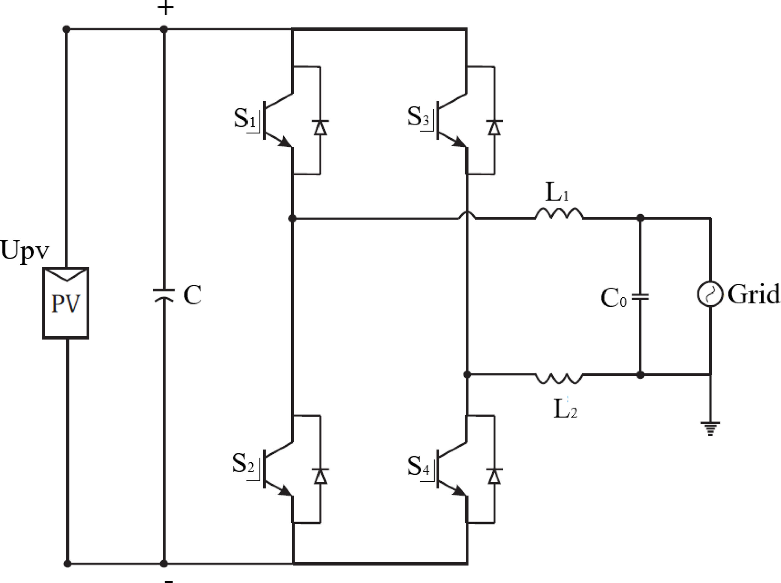
The full-bridge topology is shown in Fig.3. With the unipolar PWM modulation scheme, the operation of switches Q1 and Q2 are complementary at low frequency (60 Hz). Switches Q3 and Q4 are operated at high frequency (20 kHz), which allows for reaching an output voltage of three levels (+Vdc, 0, -Vdc), [30].
The three-level output voltage reduces the inverter’s output filter without significant losses while maintaining high efficiency. However, despite its high efficiency and simple requirements for the output filter, this topology presents a high leakage current, as the common mode voltage during its operation varies at high frequency. Therefore, using the transformerless full-bridge topology for grid-connected photovoltaic applications is unsuitable, [31].

B. HERIC
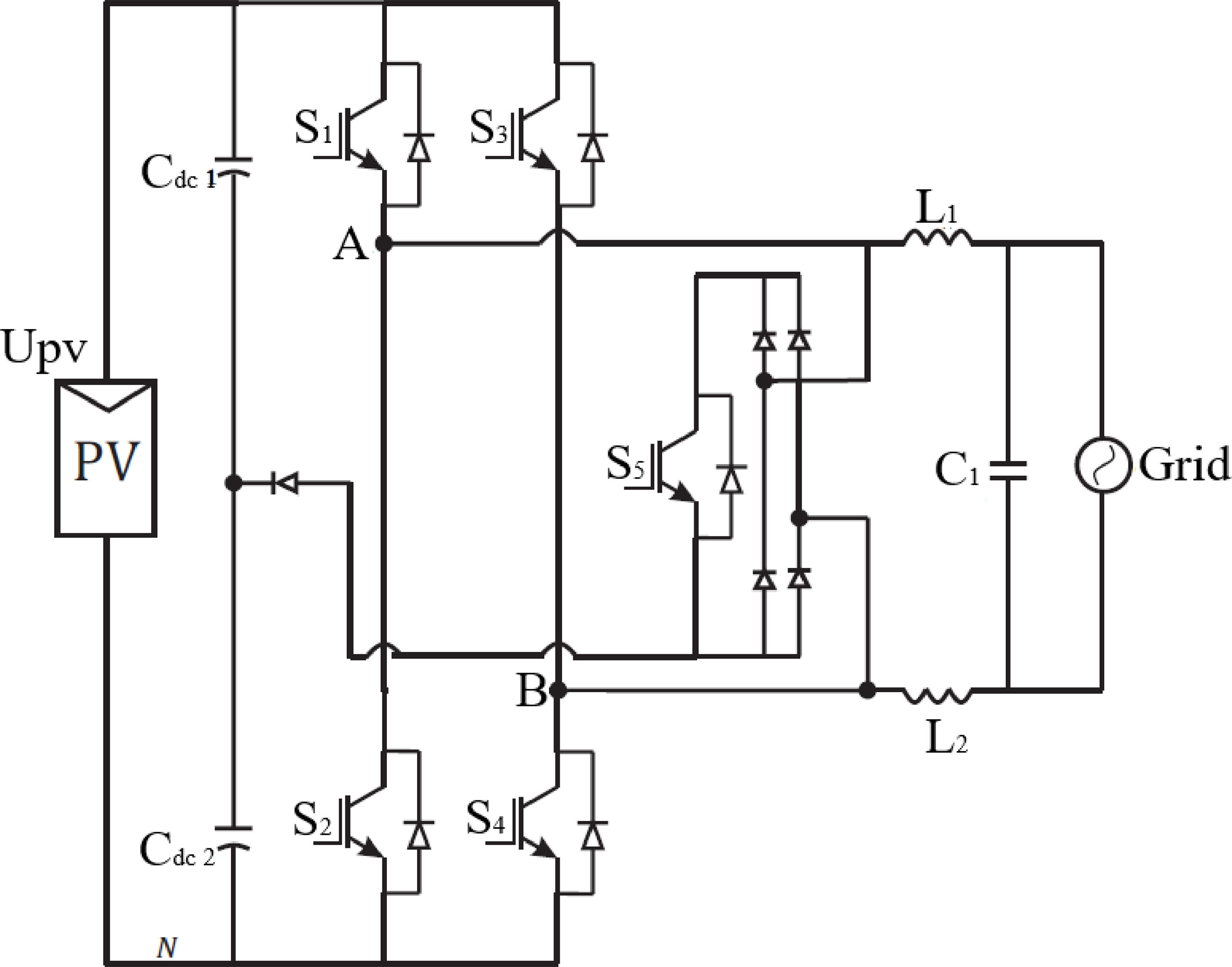
The Highly Efficient and Reliable Inverter Concept (HERIC) topology, initially proposed in 2003 by Sunways, combines the advantages of modulation in three output voltage levels, of unipolar PWM with the reduction of common mode voltage and current of escape. This way, the inverter’s efficiency is improved considerably without compromising other system parameters, [31], [32].
The zero voltage state is reached using bidirectional switches between the output terminals, 1 and 2 inversely as shown in Fig. 4, offering a free-flow path to the grid. The AC bypass switches prevent the exchange of reactive power between the output filter inductors (L1 and L2) and the DC link capacitor (Cdc), contributing to improved efficiency.

C. HB ZVR
The H-Bridge Zero-Voltage Switch Controlled Rectifier (HB-ZVR) topology was initially presented in [31]. Its main feature is to connect the midpoint of the DC link to the inverter only because the state period uses a diode rectifier bridge and a switch, as shown in Fig.5.
The zero voltage state is achieved by turning S5 on when S1 and S4 are turned off. Switching of S5 will be complementary to S1 and S4, with a small dead time to avoid a short circuit in the DC link capacitor (Cdc). Switch S5 allows the main current to flow in both directions; in this way, the inverter can supply reactive.

[31] shows that the topology HB-ZVR has a slightly lower efficiency compared to HERIC because the ’bidirectional switch’ is switched at high frequency, while in the case of the topology HERIC, the ’bidirectional switch’ is switched to the mains operating frequency. With an efficiency of approximately 94%, it is an alternative solution for transformerless grid-connected single-phase photovoltaic systems.
D. NPC- five levels
The 5-level Neutral Point Clamped Inverter (NPC) multilevel inverter configuration, presented in Fig. 6, employs five voltage levels to generate a sinusoidal output. This is achieved through a setup from a parallel arrangement of the traditional 3-level NPC. Its primary advantage is providing an output voltage with significantly reduced harmonic distortion. This is extremely important in applications requiring a high power quality standard, particularly in grid-connected renewable energy systems [33].

Reducing the breakdown voltage of the semiconductor devices to half of the DC bus voltage decreases switching losses, which are less sensitive to the switching frequency [34].
E. T-type- five levels
The 5-level T-type inverter is a multilevel alternative widely used in single-phase photovoltaic systems. It uses eight switches to generate five levels, like the full-bridge NPC, as shown in Fig 7.

However, the T-type inverter operates with fewer semiconductor devices in the current path than the full-bridge NPC, which results in low conduction losses. On the other hand, only half of the T-type inverter’s semiconductors operate at half the DC bus voltage [35].
In addition, it requires at least two switch changes in the transitions between voltage levels. Yet, the T-type inverter is considered a promising option for applications in photovoltaic systems due to its high efficiency, low conduction losses, and lower number of semiconductor devices compared to other multilevel topologies [36]–[38].
F. Floating Capacitors - five levels
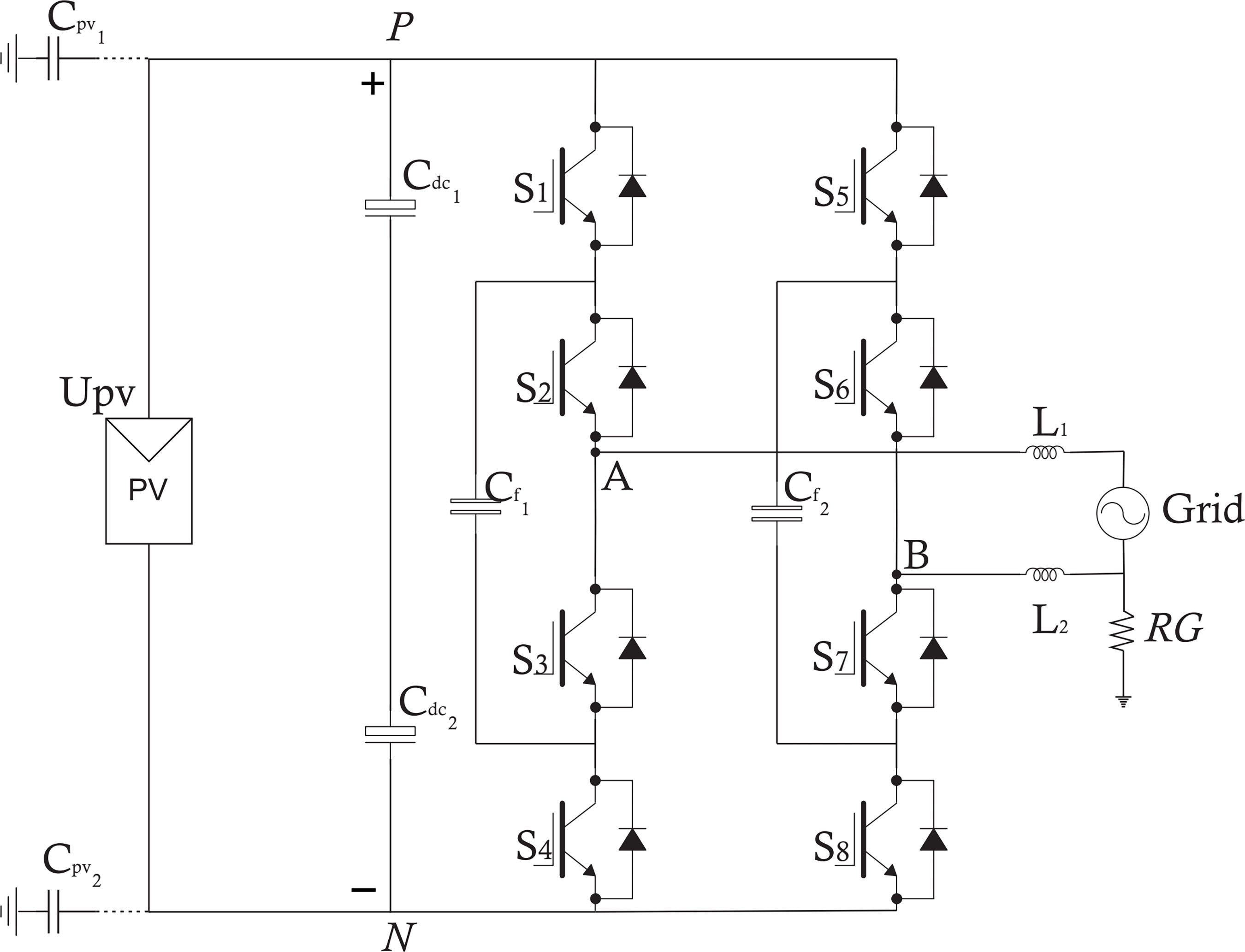
The 5-level floating capacitor (FC) inverter is a multilevel option that has been used in photovoltaic systems, consisting of two floating capacitors operating at half the DC bus voltage, generating five voltage levels [39]. As shown in Fig. 8.

The main benefit of this topology is that it reduces the number of semiconductor devices in the current path, providing lower conduction and switching losses compared to other multilevel topologies. However, a disadvantage of this configuration is the need for two robust floating capacitors, which can be a challenge in design and cost. Also, more complex control is required to balance the voltages across them [40].
IV. PROPOSED TOPOLOGY
The proposed topology of a grid-connected single-phase five-level inverter consisting of eight switches is shown in Fig. 9. The configuration switches switch from five levels to three levels at the output. The operating principle in the 5-level structure consists of using switches S7 and S8 to create an intermediate point between the input capacitors, thus allowing the voltage \(\pm 1/2V_{dc}\), as presented in Tab. 2. In the 3-level configuration, the S7 and S8 switches are not used, limiting the use of S5 and S6 - this pair of switches is essential to the assure de level 0-mode, as shown in Tab. 3. To avoid interruption in the operation of the inverters, the allowed values comply with the standards VDE 0126-1-1 and IEC 62109-2.

This configuration has the advantage of an agile change of operation from 5 levels to 3 levels, accompanied by a simplified control strategy for this transition, which will be described in more detail in section V. This puts it in a competitive position regarding operating modes compared to other topologies already recognized in the literature.
V. RESULTS
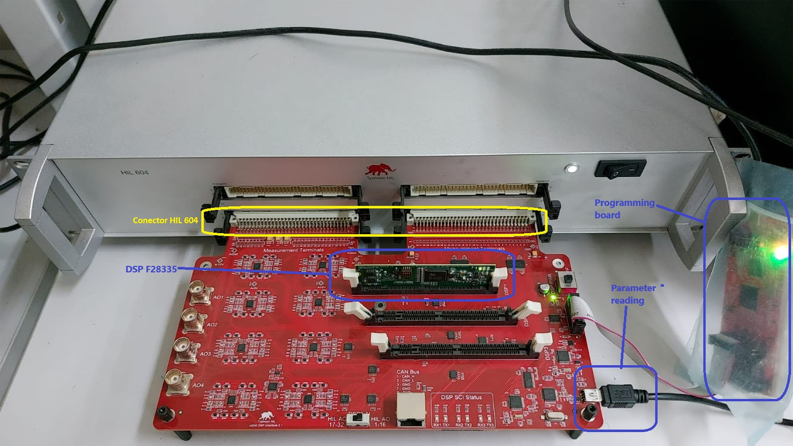
Tests were carried out on Typhoon’s Hardware-in-the-Loop (HIL) 604 platform to develop and test complex embedded systems in real time. The controllers were implemented on a Texas Instruments F28335 digital signal processor (DSP), as shown in Fig.10. The parameters used in the simulation components are listed in the Tab.4.

Two control loops are used, an internal control loop and an external control loop; one controls the current injected into the electrical grid, and the other controls the DC link voltage, respectively, so the voltage is constant. For current control, a proportional resonant (P+RES) compensator (\(C_i(s)\)) was used, which has the function of reproducing a current synchronized with the grid voltage at the inverter output to obtain a high power factor. Therefore, the current loop must be fast enough to produce the current without significant distortions. On the other hand, the voltage loop that uses a PI compensator (\(C_v(s)\)) aims to keep the DC bus voltage of the inverter constant, adjusting when variations in the irradiance of the photovoltaic array occur. Therefore, the voltage loop must be slow enough to decouple the current control loop dynamically. So, the outer loop controller must be tuned at least a decade below the inner loop controller.
The diagram of the control strategy used for the proposed inverter is illustrated in Fig. 11.

The converter system was built in the Typhoon 604 virtual environment, with the control implemented in a Texas Instruments F28335 DSP. Fig.12 displays the control operation, showing the synchronism between the injected current and the grid voltage, achieving a very high power factor (left) and the stability of the DC bus voltage (right).

The I-V and P-V curves, referring to the strings used in the simulation, are in Fig.13. The Perturb and Observe (P&O) maximum power point tracking (MPPT) algorithm was used in this simulation.
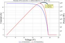
Fig. 14 shows the effect of changing the number of levels at the inverter output. The operation starts with five levels and a parasitic capacitance of value \(50nF\), considering that the panels are installed in a sunny and lightly humid environment [41]. The leakage current is within the acceptable limits, as shown in point A. Then, a disturbance was introduced at point B, varying the values from \(50nF\) to \(75nF\). This change in parasitic capacitance represents a climatic transition from a sunny, lightly humid environment to moderate rainfall. In heavy rain, these values can reach \(167nF\) [41], [42], resulting in the leakage current values above the allowed by the standards. The system recognizes the current increase and starts processing the PWM to adjust the operating values. After 200 ms, the inverter selects a new PWM pattern, reducing the leakage current values that return to below standard limits by changing the output voltage to three levels, as shown in point C.

The advantage of three-level modulation is naturally the minimization of leakage current. Compared to five-level modulation, its disadvantage is the increase in current distortion and the more significant stress on the filter and switches (due to the higher current), as shown in Tab. 5.
Therefore, it is preferable to operate with five levels whenever possible, changing to three levels in the event of excessive leakage current. A management strategy monitors the leakage current and chooses the best output voltage form.
To compare the topologies presented and prove a sound performance of the proposed topology, an analysis of the relevant quantities for the study of leakage current in photovoltaic systems connected to the transformerless grid was carried out, presented in Tab. 6.
The High leakage current negatively impacts the quality of the energy injected into the grid by increasing the spectral content of the current and compromising residual current monitoring systems, which are critical for ensuring safety. The simulation analysis revealed that each topology presents distinct advantages and limitations.
The unipolar mode of the Full-Bridge topology, the focus of this study, achieves an efficiency above 90% and reduced switching losses due to its lower semiconductor requirements, delivering a three-level output. Despite these advantages, this configuration exhibits a high leakage current and a total harmonic distortion (THD) exceeding regulatory limits, making its operation unfeasible without appropriate mitigation techniques.
Derived topologies, such as HERIC and HB-ZVR, stand out for their efficient decoupling of the DC and AC sides, ensuring low leakage current and three-level output voltage. In contrast, the NPC and T-type topologies, both operating with five levels, offer satisfactory power quality with low leakage current and are less complex compared to the Floating Capacitor inverter, which demands a more robust control strategy to regulate its voltage and maintain efficient performance across its five levels of operation.
The proposed topology outperformed all others in the five-level operation mode and demonstrated a seamless transition to three levels, maintaining response times within the recommended limits. In the three-level mode, it exhibited competitiveness by achieving low leakage current and THD, while requiring a number of semiconductors comparable to the HERIC and HB-ZVR topologies.
VI. CONCLUSION
This paper proposed a novel transformerless inverter topology for PV power systems to minimize leakage currents and improve the system’s reliability. Under normal conditions, the inverter operates with a five-level modulation strategy, ensuring high-quality performance. When leakage currents exceed standard upper limits, the topology is adapted by transitioning to a three-level configuration, utilizing a neutral clamping point to mitigate the issue effectively. By adopting six switches instead of eight, the design strikes a balance between reducing switching losses and maintaining efficiency. This flexible approach improves system availability, ensures compliance with standards, and provides a robust solution for modern photovoltaic applications.
As analyzed in the article, the Full-Bridge topology lacks an integrated leakage current mitigation mechanism, resulting in values exceeding normative limits for both leakage current and \(THD\) of grid-injected currents. This limitation demands advanced filtering techniques, significantly increasing system complexity and project costs. In contrast, The HERIC and HB-ZVR topologies incorporate mechanisms to stabilize the common-mode voltage, effectively suppressing leakage currents and improving the quality of the grid-connected output current.
Regarding five-level topologies, the NPC - five levels are introduced, offering the advantage of generating output voltage with minimal harmonic distortion. The T-type - five levels topology is also highlighted, recognized as a promising choice for photovoltaic applications due to its superior efficiency, reduced conduction losses, and fewer semiconductor components than other multilevel configurations. Lastly, the Floating Capacitors (Floating C) topology stands out for minimizing the number of semiconductor devices in the current path, effectively lowering both conduction and switching losses compared to alternative multilevel topologies.
For future work, we plan to assess the conversion efficiency of the proposed topology and conduct performance comparisons with well-established topologies from the literature, utilizing simulations and validation on a test bench.
-
1
The UN SDGs, https://sdgs.un.org/goals
ACKNOWLEDGMENT
This work was partially funded by the National Council for Scientific and Technological Development (CNPq) under grants #303859/2020-2 and #306178/2023-0 by the Coordenação de Aperfeiçoamento de Pessoal de Nivel Superior – Brasil (CAPES) – Finance Code 001.
-
PLAGIARISM POLICY
This article was submitted to the similarity system provided by Crossref and powered by iThenticate – Similarity Check.
REFERENCES
-
1 J. Twidell, Renewable Energy Resources (4th ed), Routledge, 2021, doi: 10.4324/9780429452161.
» https://doi.org/10.4324/9780429452161 - 2 J. R. Simões-Moreira, A. Hernandez Neto, A. C. d. Amaral, A. Nakano, C. R. d. F. Pacheco, D. S. Sowmy, D. Perecin, D. C. Zachariadis, E. Ioshimoto, E. S. Yamada, et al., “Energias renováveis, geração distribuída e eficiência energética”, Energias renováveis, geração distribuída e eficiência energética, p. 393, 2021.
-
3 J. Jana, H. Saha, K. Das Bhattacharya, “A review of inverter topologies for single-phase grid-connected photovoltaic systems”, Renewable and Sustainable Energy Reviews, vol. 72, pp. 1256–1270, 2017, doi: 10.1016/j.rser.2016.10.049, URL: https://www.sciencedirect.com/science/article/pii/S1364032116306943
» https://doi.org/10.1016/j.rser.2016.10.049» https://www.sciencedirect.com/science/article/pii/S1364032116306943 - 4 D. Yergin, O Novo Mapa: Energia, Clima e o Conflito entre Nações, Bookman Editora, 2023.
-
5 S. Nema, R. K. Nema, G. Agnihotri, “Inverter topologies and control structure in photovoltaic applications: A review”, Journal of Renewable and Sustainable Energy, vol. 3, no. 1, p. 012701, 01 2011, doi: 10.1063/1.3505096.
» https://doi.org/10.1063/1.3505096 -
6 D. Kolantla, S. Mikkili, S. R. Pendem, A. A. Desai, “Critical review on various inverter topologies for PV system architectures”, IET Renewable Power Generation, vol. 14, no. 17, pp. 3418–3438, 2020, doi: 10.1049/iet-rpg.2020.0317.
» https://doi.org/10.1049/iet-rpg.2020.0317 -
7 L. Hassaine, E. OLias, J. Quintero, V. Salas, “Overview of power inverter topologies and control structures for grid connected photovoltaic systems”, Renewable and Sustainable Energy Reviews, vol. 30, pp. 796–807, 2014, doi: 10.1016/j.rser.2013.11.005, URL: https://www.sciencedirect.com/science/article/pii/S1364032113007545
» https://doi.org/10.1016/j.rser.2013.11.005» https://www.sciencedirect.com/science/article/pii/S1364032113007545 -
8 I. D. Pharne, Y. N. Bhosale, “A review on multilevel inverter topology”, in 2013 International Conference on Power, Energy and Control (ICPEC), pp. 700–703, 2013, doi: 10.1109/ICPEC.2013.6527746.
» https://doi.org/10.1109/ICPEC.2013.6527746 -
9 V. Agelidis, D. Baker, W. Lawrance, C. Nayar, “A multilevel PWM inverter topology for photovoltaic applications”, in ISIE ’97 Proceeding of the IEEE International Symposium on Industrial Electronics, vol. 2, pp. 589–594 vol.2, 1997, doi: 10.1109/ISIE.1997.649027.
» https://doi.org/10.1109/ISIE.1997.649027 -
10 C. C. A. De Carvalho, P. R. D. R. Da Silva, J. A. Pomilio, J. M. Araújo, “Leakage Current Mitigation in Transformerless Grid-Connected PV Inverters Through Level Modulation Switching”, in 2023 IEEE 8th Southern Power Electronics Conference (SPEC), pp. 1–7, IEEE, 2023, doi: 10.1109/SPEC56436.2023.10407919.
» https://doi.org/10.1109/SPEC56436.2023.10407919 - 11 T. Kerekes, Analysis and modeling of transformerless photovoltaic inverter systems, Institut for Energiteknik, Aalborg Universitet, 2009.
-
12 Y. R. Kafle, G. E. Town, X. Guochun, S. Gautam, “Performance comparison of single-phase transformerless PV inverter systems”, in 2017 IEEE Applied Power Electronics Conference and Exposition (APEC), pp. 3589–3593, 2017, doi: 10.1109/APEC.2017.7931213.
» https://doi.org/10.1109/APEC.2017.7931213 -
13 S. Yu, J. Wang, X. Zhang, F. Li, “Complete parasitic capacitance model of photovoltaic panel considering the rain water”, Chinese Journal of Electrical Engineering, vol. 3, no. 3, pp. 77–84, 2017, doi: 10.23919/CJEE.2017.8250427.
» https://doi.org/10.23919/CJEE.2017.8250427 -
14 B. Chen, J.-S. Lai, “A family of single-phase transformerless inverters with asymmetric phase-legs”, in 2015 IEEE Applied Power Electronics Conference and Exposition (APEC), pp. 2200–2205, 2015, doi: 10.1109/APEC.2015.7104654.
» https://doi.org/10.1109/APEC.2015.7104654 -
15 Y. P. Siwakoti, F. Blaabjerg, “Common-ground-type transformerless inverters for single-phase solar photovoltaic systems”, IEEE Transactions on Industrial Electronics, vol. 65, no. 3, pp. 2100–2111, 2017, doi: 10.1109/TIE.2017.2740821.
» https://doi.org/10.1109/TIE.2017.2740821 -
16 T. Ahmad, Z. Miao, “Common mode voltage reduction schemes for voltage source converters in an autonomous microgrid”, in 2015 North American Power Symposium (NAPS), pp. 1–5, IEEE, 2015, doi: 10.1109/NAPS.2015.7335128.
» https://doi.org/10.1109/NAPS.2015.7335128 - 17 H. Abu-Rub, M. Malinowski, K. Al-Haddad, Power electronics for renewable energy systems, transportation and industrial applications, John Wiley & Sons, 2014.
-
18 Y. P. Siwakoti, F. Blaabjerg, “Common-ground-type transformerless inverters for single-phase solar photovoltaic systems”, IEEE Transactions on Industrial Electronics, vol. 65, no. 3, pp. 2100–2111, 2018, doi: 10.1109/TIE.2017.2740821.
» https://doi.org/10.1109/TIE.2017.2740821 -
19 M. Biswas, S. P. Biswas, M. R. Islam, M. A. Rahman, K. M. Muttaqi, “A new H7 transformer-less single-phase inverter to improve the performance of grid-connected solar photovoltaic systems”, in 2021 IEEE Industry Applications Society Annual Meeting (IAS), pp. 1–6, IEEE, 2021, doi: 10.1109/IAS48185.2021.9677126.
» https://doi.org/10.1109/IAS48185.2021.9677126 -
20 C. C. De Carvalho, G. C. Prym, G. P. De Lima, P. R. Da Silva, M. G. Villalva, J. M. Araújo, “A Novel H7 Transformerless SinglePhase Inverter Topology for Leakage Current Reduction”, in 2022 14th Seminar on Power Electronics and Control (SEPOC), pp. 1–6, IEEE, 2022, doi: 10.1109/SEPOC54972.2022.9976438.
» https://doi.org/10.1109/SEPOC54972.2022.9976438 -
21 Ó. López, R. Teodorescu, F. Freijedo, J. Doval-Gandoy, “Eliminating ground current in a transformerless photovoltaic application”, 2007 IEEE Power Engineering Society General Meeting, PES, 2007, doi: 10.1109/PES.2007.385789.
» https://doi.org/10.1109/PES.2007.385789 -
22 S. Araujo, P. Zacharias, B. Sahan, “Novel grid-connected non-isolated converters for photovoltaic systems with grounded generator”, in 2008 IEEE Power Electronics Specialists Conference, pp. 58–65, IEEE, jun 2008, doi: 10.1109/PESC.2008.4591897.
» https://doi.org/10.1109/PESC.2008.4591897 - 23 DIN, DIN. VDE V 0126-1-1, Automatic disconnection device between a generator and the public low voltage grid, VDE STANDARTS, 2006.
- 24 IEC, IEC. 62109-2, Safety of power converters for use in photovoltaic power systems – Part 2: Particular requirements for inverters, IEC STANDARTS, 2011.
-
25 G. C. S. Prym, C. C. A. De Carvalho, G. P. De Lima, P. R. D. R. Da Silva, J. M. Araújo, M. G. Villalva, “Topologies Analysis of Transformerless PV Inverters with Leakage Current Reduction”, in 2022 14th Seminar on Power Electronics and Control (SEPOC), pp. 1–6, 2022, doi: 10.1109/SEPOC54972.2022.9976421.
» https://doi.org/10.1109/SEPOC54972.2022.9976421 - 26 D. VDE, “0126-1-1”, Eigenerzeugungsanlagen am Niederspannungsnetz, 2006.
-
27 H. F. Xiao, K. Lan, L. Zhang, “A quasi-unipolar SPWM full-bridge transformerless PV grid-connected inverter with constant commonmode voltage”, IEEE Transactions on Power Electronics, vol. 30, no. 6, pp. 3122–3132, 2014, doi: 10.1109/TPEL.2014.2331367.
» https://doi.org/10.1109/TPEL.2014.2331367 -
28 M. N. H. Khan, M. Forouzesh, Y. P. Siwakoti, L. Li, T. Kerekes, F. Blaabjerg, “Transformerless inverter topologies for single-phase photovoltaic systems: A comparative review”, IEEE Journal of Emerging and Selected Topics in Power Electronics, vol. 8, no. 1, pp. 805– 835, 2019, doi: 10.1109/JESTPE.2019.2908672.
» https://doi.org/10.1109/JESTPE.2019.2908672 -
29 A. Salem, K. Sedraoui, “Highly Efficient Transformerless Inverter with Flying-Capacitor Buck–Boost for Single-Phase GridConnected PV Systems”, Applied Sciences, vol. 11, no. 22, 2021, doi: 10.3390/app112210841, URL: https://www.mdpi.com/2076-3417/11/22/10841
» https://doi.org/10.3390/app112210841» https://www.mdpi.com/2076-3417/11/22/10841 -
30 M. N. H. Khan, M. Forouzesh, Y. P. Siwakoti, L. Li, T. Kerekes, F. Blaabjerg, “Transformerless Inverter Topologies for Single-Phase Photovoltaic Systems: A Comparative Review”, IEEE Journal of Emerging and Selected Topics in Power Electronics, vol. 8, no. 1, pp. 805–835, 2020, doi: 10.1109/JESTPE.2019.2908672.
» https://doi.org/10.1109/JESTPE.2019.2908672 -
31 T. Kerekes, R. Teodorescu, P. Rodríguez, G. Vázquez, E. Aldabas, “A New high-efficiency single-phase transformerless PV inverter topology”, IEEE Transactions on Industrial Electronics, vol. 58, no. 1, pp. 184–191, 2011, doi: 10.1109/TIE.2009.2024092.
» https://doi.org/10.1109/TIE.2009.2024092 -
32 Y. Tang, W. Yao, P. C. Loh, F. Blaabjerg, “Highly Reliable Transformerless Photovoltaic Inverters with Leakage Current and Pulsating Power Elimination”, IEEE Transactions on Industrial Electronics, vol. 63, no. 2, pp. 1016–1026, 2016, doi: 10.1109/TIE.2015.2477802.
» https://doi.org/10.1109/TIE.2015.2477802 -
33 V. Pires, J. Martins, D. Foito, H. Chen, “A grid connected photovoltaic system with a multilevel inverter and a Le-Blanc transformer”, International Journal of Renewable Rnergy Research, vol. 2, no. 1, pp. 84–91, 2012, doi: 10.20508/ijrer.v2i1.131.g89.
» https://doi.org/10.20508/ijrer.v2i1.131.g89 -
34 Y. P. Siwakoti, A. Mahajan, D. J. Rogers, F. Blaabjerg, “A novel seven-level active neutral-point-clamped converter with reduced active switching devices and DC-link voltage”, IEEE Transactions on Power Electronics, vol. 34, no. 11, pp. 10492–10508, 2019, doi: 10.1109/TPEL.2019.2897061.
» https://doi.org/10.1109/TPEL.2019.2897061 - 35 O. Abdel-Rahim, M. Takeuchi, H. Funato, H. Junnosuke, “T-type three-level neutral point clamped inverter with model predictive control for grid connected photovoltaic applications”, in 2016 19th International Conference on Electrical Machines and Systems (ICEMS), pp. 1–5, IEEE, 2016.
-
36 S. K. Kuncham, K. Annamalai, N. Subrahmanyam, “A two-stage Ttype hybrid five-level transformerless inverter for PV applications”, IEEE Transactions on Power Electronics, vol. 35, no. 9, pp. 9510– 9521, 2020, doi: 10.1109/TPEL.2020.2973340.
» https://doi.org/10.1109/TPEL.2020.2973340 -
37 M. Aly, E. M. Ahmed, M. Shoyama, “Modulation method for improving reliability of multilevel T-type inverter in PV systems”, IEEE Journal of Emerging and Selected Topics in Power Electronics, vol. 8, no. 2, pp. 1298–1309, 2019, doi: 10.1109/JESTPE.2019.2898105.
» https://doi.org/10.1109/JESTPE.2019.2898105 - 38 M. Schweizer, J. W. Kolar, “High efficiency drive system with 3-level T-type inverter”, in Proceedings of the 2011 14th European conference on power electronics and applications, pp. 1–10, IEEE, 2011.
-
39 N. Q. T. Vo, D.-C. Lee, “Bootstrap power supply for threelevel neutral-point-clamped voltage source inverters”, in Proceedings of The 7th International Power Electronics and Motion Control Conference, vol. 2, pp. 1038–1043, IEEE, 2012, doi: 10.1109/IPEMC.2012.6258948.
» https://doi.org/10.1109/IPEMC.2012.6258948 -
40 S. Madichetty, A. Dasgupta, S. Mishra, C. K. Panigrahi, G. Basha, “Application of an advanced repetitive controller to mitigate harmonics in MMC with APOD scheme”, IEEE Transactions on Power Electronics, vol. 31, no. 9, pp. 6112–6121, 2015, doi: 10.1109/TPEL.2015.2501314.
» https://doi.org/10.1109/TPEL.2015.2501314 -
41 W. Chen, X. Yang, W. Zhang, X. Song, “Leakage Current Calculation for PV Inverter System Based on a Parasitic Capacitor Model”, IEEE Transactions on Power Electronics, vol. 31, no. 12, pp. 8205–8217, 2016, doi: 10.1109/TPEL.2016.2517740.
» https://doi.org/10.1109/TPEL.2016.2517740 -
42 S. Yu, J. Wang, X. Zhang, F. Li, “Complete parasitic capacitance model of photovoltaic panel considering the rain water”, Chinese Journal of Electrical Engineering, vol. 3, no. 3, pp. 77–84, 2017, doi: 10.23919/CJEE.2017.8250427.
» https://doi.org/10.23919/CJEE.2017.8250427
Edited by
-
Associate Editor
Satish N. Banavath https://orcid.org/0000-0002-4406-9822
-
Editor-in-Chief
Heverton A. Pereira https://orcid.org/0000-0003-0710-7815