 Horizontal seismic coefficient for 2D pseudo-static slope stability of earth and tailings dams
Abstract
This paper presents a review on the main simplified methods to estimate the horizontal seismic coefficient for 2D pseudo-static slope stability in earth and tailings dams. The pseudo-static method is conceptually simple, required for stability of soil slopes by seismic codes and regulatory agencies, but from a geotechnical point of view is a complicated approach, given the difficulty to select appropriate values of the seismic coefficient and the shear strength parameters. Most of the simplified methods are based on a decoupled approach where the numerical or analytical solution is obtained in two independent steps: firstly, the dynamic response of the dam, followed by evaluation of the permanent displacement of the sliding mass. The seismic forces in a decoupled approach are not adequately considered in the first step since the displacements along the sliding surface are neglected. These forces may exceed the dynamic strength of the soil, leading to an overestimation of the response, especially when the predominant frequency of the earthquake is close to the fundamental frequency of the sliding mass. On the other hand, coupled analyses capture the interaction between the dynamic response and the sliding surface response to compute permanent displacements directly, thus enabling a correlation between the horizontal seismic coefficient and allowable permanent displacements. The seismic response of the slope is represented by the fundamental period of the potential sliding mass, and the site-dependent seismic demand is characterized by the 5% damped elastic design spectral acceleration at a degraded period of the potential sliding mass.
Keywords:
Pseudo-static stability analysis; Decoupled stability analysis; Coupled stability analysis; Seismic coefficient; Earth dam; Tailings dam
1. Introduction
A 2D pseudo-static slope stability analysis refers to the approach in which the effects of an earthquake are represented by a horizontal acceleration that produces an inertia force applied at the center of gravity of the sliding soil mass. The pseudo-static factor of safety is generally calculated using computer programs for static slope stability analysis (method of slices), by adding inertia forces applied at the center of gravity of the slices. The first application of this method is attributed to Terzaghi (1950) who considered a horizontal inertia force with magnitude obtained by multiplying the weight of the soil mass by the horizontal seismic coefficient . The accuracy is dependent on the value of the seismic coefficient that represents the non-uniform distribution of horizontal accelerations in the soil mass above the potential sliding surface. Until the 1970s, horizontal seismic coefficients between 0.05 and 0.15 were used in the United States (Seed, 1979) and between 0.10 and 0.25 in Chile, Peru, Mexico and Japan.
Despite being a method required for estimating the stability of soil slopes by seismic codes and regulatory agencies, the pseudo-static method has several limitations:
-
It is based on the simplifying assumption that the dam is a rigid body that moves along with a rock base, experiencing uniform horizontal accelerations along its height.
-
It assumes that the horizontal acceleration in the sliding soil mass is permanent and acts in a single direction. Actually, the accelerations are cyclical and multidirectional, producing a reversal of the shear stresses in the soil mass.
-
A pseudo-static factor of safety lower than unity does not mean collapse but it is an indication of limited movement of the slope for a brief period of time. Likewise, a factor of safety higher than unity does not mean stability because the slope may fail during a gradual redistribution of stresses and dissipation of seismically induced excess pore pressure in the post-earthquake condition. Pseudo-static analyses are not recommended for materials in the slope system and its foundation that may suffer a significant loss of strength (more than 15%) due to cyclic loading (Seed, 1979). If there is a possibility of a significant loss of strength (liquefaction, flow slide) the assessment of the extent of the loss and the associated consequences should be the focus of the investigation. The basic assumption of the pseudo-static approach is that material properties do not change significantly during shaking.
-
Neither the peak drained strength nor the peak undrained strength are appropriate for analysis considering materials that exhibit significant loss of shear strength under cyclic loading.
-
It is difficult to select the horizontal seismic coefficient but it is important not to associate it with the maximum horizontal acceleration that acts only instantaneously in the soil mass, since this assumption would produce excessively conservative (low) values.
-
The method considers only the influence of the earthquake acceleration but not the effects of the magnitude or distance of the event. Large magnitude earthquakes have a long duration, a greater number of cycles and are more devastating than events of smaller magnitude.
-
The approach considers that slope instability is the only failure mode, but other types of seismic damage may occur in earth or tailings dams such as liquefaction of saturated cohesionless materials, longitudinal cracks near the crest due to shear deformations and high tensile strains during lateral vibration, differential settlements of the crest and reduction of the freeboard due to lateral deformations or soil densification, transverse cracks caused by tensile deformations near the abutments, piping failures in cracks of cohesive soil zones.
The pseudo-static method is quite limited (“the concept it conveys of earthquake effects on slopes is very inaccurate to say the least” – Terzaghi, 1950) because it is evident that the consideration of constant inertia forces, in magnitude and direction, represents a simplification of the real dynamic problem. As stated by Jibson (1993), “the utility of pseudo-static analysis is thus limited because it provides only a single numerical threshold below which no displacement is predicted and above which total, but undefined, failure is predicted”.
According to Seed (1979), the main reason for the widespread acceptance of this conceptually simple, but geotechnically complicated method, was that few engineers were aware of dam failures designed according to the method. Few large dams had been subjected to strong earthquakes and few reports on the seismic behavior of these structures, concerning construction procedures and design criteria, were available. When dam failures occurred, the reason was attributed to the fact that the structures were old and poorly constructed, but not to the design method itself.
Seed et al. (1969a, 1975) reported slope failures even when the calculated pseudo-static factor of safety was greater than 1. A historical case is the collapse in 1971 of the Lower San Fernando dam in Southern California, which provided 80% of the water supply to the city of Los Angeles. When hit by an earthquake of magnitude = 6.6, the dam crest was lowered by 9.1 m following the collapse of the upstream slope. For this structure, the calculated pseudo-static factor of safety was 1.3 considering a horizontal seismic coefficient = 0.15. Five years earlier, the dam had been judged stable against seismic events by geotechnical engineering consultants and regulatory agencies. Another historical case was the failure of the Sheffield dam in Santa Barbara, hit in 1925 by an earthquake of magnitude 6.3, with the collapse of the downstream slope, designed with a seismic coefficient = 0.1 and a pseudo-static factor of safety 1.31.
According to Wieland (2014), up until March 2011 eight people died due to the rupture of a large earth dam, when the Tohoku earthquake in Japan, of magnitude 9.0, caused the release of water from the Fujinama dam reservoir. However, hundreds of people lost their lives in accidents involving tailings dam ruptures during earthquakes, including the El Soldado dam in Chile in 1965 (Lyu et al., 2019) with the release of liquefied tailings that advanced for 12 km, killing more than 200 people. In the period 1910–1999, Zare et al. (2024) reported 47 failures of tailings dams due to earthquakes.
Until 1989, when ICOLD published the first Bulletin 72 (ICOLD, 1989) on recommendations for selection of seismic parameters for large dams, most structures were designed to resist earthquakes using the pseudo-static method with a horizontal seismic coefficient between 0.1 and 0.15. Since the 1970s, efforts have been made to better understand the seismic behavior of dams through field and laboratory investigations of dynamic properties of soils under cyclic loading, as well as through experimental observations of field cases and numerical back-analysis of important historical events, such as the seismic landslides in Anchorage (1964 Alaska earthquake), Mochikoshi tailings dam in Japan in 1978 (Ishihara, 1984) and the aforementioned Lower San Fernando in 1971 (Seed et al., 1975) and Sheffield in 1925 (Seed et al., 1969a) dams.
Numerical stress-strain analyses are the gold standard for studies on the seismic behavior of dams when there is sufficient quantity and quality of geotechnical data to merit them. For earth and tailings dams adjacent to critical infrastructure, cultural assets, areas of environmental preservation or downstream existence of population groups, the cost and effort in obtaining the parameters necessary for a coupled elastoplastic analysis are fully justified.
2. D’Alembert’s principle
It is convenient to recall a simple and fundamental concept of dynamics that explains the reason for the pseudo-static terminology. According to Newton’s second law (Equation 1), the resultant of the active and reactive forces acting on a body is equal to the product of its mass m and the acceleration .
The inertia force is also defined as the product of mass and acceleration (Equation 2), but its direction is opposite to the acceleration because it counteracts the movement of the body.
Equation 2 mathematically defines D’Alembert’s principle: if at a given moment the inertia force is added to the active and reactive forces acting on a body, then the system of forces will be in equilibrium, and the equations of statics can be applied. This principle underlies the theoretical concept for solving problems in dynamics by means of equilibrium methods considering the static condition, thus explaining the terminology pseudo-static analysis.
3. Dynamic undrained strength
The static peak undrained strength of soils is defined as the maximum deviator stress supported by the soil sample in an undrained triaxial test under monotonic loading. Makdisi & Seed (1978) observed during cyclic triaxial tests in soils exhibiting small increases in pore pressure under cyclic loading (clayey soils, dry or partially saturated granular soils, dense saturated granular soils) that 80% of the static undrained strength represents a threshold between the occurrence of small and large deformations induced by a large number of loading cycles (more than 100). For determination of the factor of safety by the pseudo-static method, Makdisi & Seed recommended the use of 80% of the peak static undrained strength as an approximation of the peak dynamic undrained strength in soils not susceptible to cyclic liquefaction or do not suffer a loss of shear strength greater than 15%.
Duncan et al. (2014) argued that the reduction in the peak static undrained strength can be ignored due to the effects of seismic loading velocity. Most soils subjected to rapid loading exhibit an initial undrained strength 20% to 50% higher than that determined in conventional static laboratory tests, where the time to reach failure can take several or many minutes.
For plastic clays, Biscotin & Pestana (2000) reported in the first loading cycle a value of peak dynamic undrained strength 1.3 times higher than the static undrained strength measured in soft plastic clay with conventional vane tests, while Rau (1998) found a 10% - 30% decay after additional cycles due to cyclic degradation, depending on the number of cycles. For large magnitude earthquake with many cycles of loading, Bray & Macedo (2023a) suggested to increase the peak static undrained strength by a rate of loading factor , in order to consider the influence of velocity on the undrained strength, and to multiply the result by a cyclic degradation factor to account for cyclic degradation effects. Additionally, according to Bray & Macedo, a progressive failure factor is generally appropriate for moderately sensitive plastic clays exhibiting significant post-peak strain softening that takes into account the fact that the dynamic shear strength may not be mobilized along the entire failure surface. They also recommended a distributed shear deformation factor to consider that shear deformation can accumulate within part of the potential sliding mass before the localized sliding surface is fully developed. This shear deformation zone is considerably thicker than the localized sliding surface.
Combining the above factors, a typical value of the peak dynamic undrained strength for plastic clays would be estimated according to Equations (3) and (4):
The use of peak dynamic undrained strength is appropriate for clays exhibiting hardening or for predicting limited permanent displacements. For moderate displacements in clays exhibiting post-peak softening, the dynamic undrained strength can be adjusted as a function of the level of shear deformation induced by the earthquake; if large displacements are anticipated, the residual undrained strength should be used. According to Biscotin & Pestana (2000), the residual undrained strength of clay is insensitive to the loading rate, so that the dynamic residual undrained strength can be assumed equal to the static residual undrained strength.
4. Horizontal seismic coefficient
The choice of represents one of the most important and the most difficult aspects of the pseudo-static method, because soils are deformable materials and the dynamic response depends on the characteristics of the earthquake. Since the 1970s, several researchers have proposed values of the seismic coefficient based on the maximum horizontal acceleration at the crest of an earth dam (Makdisi & Seed, 1978), earthquake magnitude (Seed, 1979), fraction of the maximum acceleration at the ground surface (Eurocode 8, 2004), maximum acceleration at the outcrop rock (Hynes-Griffin & Franklin, 1984), spectral acceleration (Bray & Travasarou, 2009; Bray & Macedo, 2019, 2021a,b). None of these methods are recommended for dams (including the foundation soil) that may suffer significant loss of strength due to cyclic loading. For slopes that are expected to experience significant loss of strength, more advanced methods are required based on non-linear effective stress analysis.
4.1 Decoupled Hynes-Griffin & Franklin method (1984)
This method, developed for application in earth dams, is quite popular among geotechnical engineers as a screening procedure for calculating the seismic stability of soil slopes. Its main advantage is the estimation of the horizontal seismic coefficient as a function of the peak acceleration at the outcrop rock (), not requiring further studies on site effects. It is a decoupled method, whose solution was obtained in two independent stages: firstly, the dynamic response of the dam, followed by the determination of the permanent displacements of the sliding soil mass.
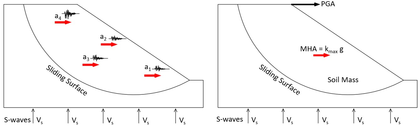
To obtain the dynamic response of the dam, Hynes-Griffin & Franklin used the Sarma’s (1979) analytical solution for the viscoelastic response of a triangular cross-section shear beam. By varying the input parameters of the closed-form solution, such as the impedance ratio (Equation 5) and thickness of the foundation layer (Equation 6), they modeled the variation with depth of the horizontal acceleration induced by 27 strong earthquakes. These accelerations were then averaged over wedges that approximately represented potential sliding soil masses, in equivalent volume and location. The maximum average acceleration acting on the sliding soil mass at any time corresponds to the seismic demand (Figure 1). The ratio of to the peak rock acceleration was taken as the amplification factor , where is the maximum seismic coefficient acting on the potential sliding mass of deformable soil. Observe that the method can be used in embankments of approximately triangular or trapezoidal cross-sections but not in natural slopes.
where and are the shear wave velocities across the embankment and the foundation soil, respectively, and represent the specific masses of the embankment and the foundation soil, respectively, is the embankment height and is the thickness of the foundation soil.

The maximum mean horizontal acceleration controls the maximum horizontal inertia force acting on the deformable sliding mass. For rigid soils .
To obtain the permanent displacements of the sliding soil mass, Hynes-Griffin & Franklin used the Newmark (1965) rigid block analogy, double-integrating as a function of time 340 earthquake acceleration histories and 6 synthetic acceleration records with magnitude < 8.0. The peak dynamic undrained strength of soils was assumed equal to 80% of the peak static undrained strength (Makdisi & Seed, 1978).
For a sliding surface passing through the entire height of the dam (y/H = 1), corresponding to the amplification factor , they recommended the horizontal seismic coefficient in order to limit in 100 cm the permanent displacement of the soil mass. The choice of 100 cm was justified by the argument that “such a deformation would surely be considered serious damage, but it could be tolerated in most dams without immediately threatening the integrity of the reservoir” (Hynes-Griffin & Franklin, 1984). The sliding surface at depth y/H = 1 was also selected because the movement of the soil mass could entail ruptures in drains and other critical internal structures of earth dams. It is possible to estimate the permanent displacement of sliding masses at different relative depths y/H using the curves available in Hynes-Griffin & Franklin (1984).
The seismic coefficient reflects the conservatism of the approach ( 100 cm for the sliding mass at y/H = 1), but it is consistent with the primary purpose of the method to be a preliminary calculation tool, provided < 8.0 and the values of the dimensionless parameters m and q are within the range given by Equations 5 and 6.
4.2 EN 1998-5 method (Eurocode 8, 2004)
The European Standard EN 1998-5 (Eurocode 8, 2004) recommends equivalent to 50% of the maximum acceleration at the ground surface (PGA) as a way of limiting permanent displacements and not to compromise the slope stability (Equation 7). The equation was developed for slopes in general and not specifically for dams. The 50% PGA reduction factor was selected based on empirical formulation, back-analysis of historical cases and experimental observation of the seismic behavior of natural slopes and embankments. It should be understood that by choosing a certain fraction of the PGA for the definition of it is implicitly assumed that permanent displacements will occur. The engineer can make the decision to increase the restriction on permanent displacement levels by choosing a higher percentage of the PGA. If is selected then the permanent displacement of the deformable soil mass would be zero because the seismic demand does not exceed the dynamic strength, i.e. ky/kmax ≥ 1 where ky is the yield coefficient corresponding to .
where is a seismic amplification factor for estimating the PGA, depending on the site class (Table 1).
Topographic effects can also be considered in Equation 7 by means of a topographic amplification factor (Annex A of EN 1998-5, 2004) applied as a frequency-independent scaling factor. For average slope angles of less than about 15° the topographic effects may be neglected. In case of dams, where the crest width is considerably smaller than the base width, the value ≥ 1.4 should be used near the top of slopes with average inclination greater than 30° and ≥ 1.2 is recommended for inclinations between 15° and 30°. In the existence of a loose surface layer more than 5 m thick, the above values should be increased by 20%. Topographic effects are greatest for shallow landslides near the crest, and it can be assumed that decreases linearly with depth of the sliding surface until reaching the minimum value = 1 at the toe of the slope. In the latter case, the topographic effects may be neglected in a pseudo-static stability analysis.
The vertical seismic coefficient is estimated by Equations 8 and 9, depending on the magnitude of the most significant earthquake contributing to the local hazard.
The second generation of European codes for seismic design of earthquake-resistant structures EN 1998-5 (Eurocode 8, 2024), currently under review by the countries of the European Union, will replace the EN 1998-5 method (Eurocode 8, 2004) with full implementation by 2028.
4.3 Decoupled Papadimitriou et al. (2014) method
Papadimitriou et al. (2014) carried out 110 two-dimensional nonlinear seismic analyses (plane strain condition) considering 4 dams (1 rockfill dam 20 m high, 3 zoned earth dams 40, 80 and 120 m high). Numerical results from 1084 potential sliding masses were used for a decoupled statistical regression to establish correlations between the horizontal seismic coefficient and the level of allowable displacements that the dams could sustain.
These correlations should be used with great caution since they are subject to the following limitations: earth/rockfill dam atop a rock foundation or soil layer with a minimum thickness of 5 m and S-wave velocity greater than 250 m/s, PGA at the ground surface between 0.05g and 0.50g, earthquake with moment magnitude > 5.5 and predominant period between 0.14 and 0.50 s. The behavior of the dams under cyclic loading was simulated with a nonlinear constitutive model with hysteretic damping, implemented by Papadimitriou et al. (2014) in the FLAC 2D software.
The method involves several approximations and site-specific data requirements that may limit its practical application, particularly in regions with diffuse seismicity like Brazil. Among the main restrictions, the following are mentioned:
-
It requires the specification of more than a dozen parameters, most of which related to the description of the sliding mass, but only two associated with the characteristics of the earthquake (maximum acceleration and the predominant period of the earthquake). These two parameters are usually obtained from probabilistic seismic hazard analyses (PSHA) as a function of the return period of the design motion. In the absence of this information, estimates of the predominant period as a function of the earthquake magnitude and the source-to-site distance using relationships proposed in the literature (such as Seed et al., 1969b; Idriss, 1991) for shallow crustal earthquakes along active plate margins in the Western United States are not applicable in the Brazilian seismic scenario, a SCR region (Stable Continental Region) characterized by higher bedrock stiffness and diffuse seismicity, where source-to-site distances are difficult to be determined.
-
Numerical analyses were performed considering variants of horizontal acceleration histories of only 4 shallow crustal earthquakes in Greece. One of the major difficulties in estimating seismic displacements is due to the inherent uncertainties in the acceleration histories of the design motion. This was the main argument used by Bray & Travasarou (2007) and Bray & Macedo (2019, 2021a) to justify the development of a 1D coupled model for estimating displacements induced by a very large number of acceleration histories.
-
The correlation between the horizontal seismic coefficient and the allowable permanent displacement was made using analytical solutions from literature, based on the Newmark (1965) rigid block analogy. Two solutions were chosen, the first considering a simpler analytical form of Cai & Bathurst (1996) equation, suggested for the initial design, and the second one based on the Whitman & Liao (1984) equation, for the final design, replacing the PGA and PGV parameters of the analytical solutions by the acceleration and maximum velocity of the sliding mass computed in the numerical solutions. However, it is noteworthy that the Whitman & Liao solution refers to permanent displacements experienced by gravity walls and not by soil slopes.
5. Coupled Bray & Macedo (2019, 2021a,b, 2024) method
In decoupled analyses, the seismic forces are not adequately modeled because the displacements along the potential sliding surface are ignored in the first calculation step. These forces could eventually exceed the dynamic resistance of the soil, leading to an overestimation of the response, especially when the predominant earthquake frequency is close to the fundamental frequency of the sliding soil mass.
Bray & Travasarou (2009) observed that using a single value of the seismic coefficient in a large geographic region or country is not appropriate, recommending its determination through a coupled method based on estimates of local seismic hazard and the level of allowable permanent displacements () induced by cyclic shear. The method was based on research of Bray & Travasarou (2007) for predicting permanent displacements of potential sliding masses subjected to horizontal acceleration records of shallow crustal earthquakes from the NGA-West database. It can be applied to earth and tailings dams, natural slopes, compacted earth fills and solid-waste landfills.
The Bray & Travasarou (2009) method was updated by Bray & Macedo (2019, 2021a, b, 2024) increasing from 688 to 6711 the number of horizontal acceleration histories of shallow crustal earthquakes, considering moment magnitude 5 ≤ ≤ 7.9 with epicentral distance < 200 km recorded in sites class A, B, C or D (NEHRP, 2003), defined in Table 2.
If in a pseudo-static stability analysis, the seismic coefficient determined by Equations 10-14 results in a factor of safety , then the predicted permanent displacement should be equal to or less than the allowable permanent displacement . The minimum acceptable factor of safety should not be considered greater than 1 because varies non-linearly, so that the effects of a minimum factor of safety greater than 1 cannot be estimated.
with
where (cm) represents the allowable permanent displacement induced by shear, is the 5% damped elastic spectral acceleration of the site’s design ground motion at the degraded period of the sliding soil mass, is the moment magnitude, denotes a normally distributed random variable with zero mean and standard deviation = 0.74. Considering the consequences of permanent displacements higher than the desired performance level, the engineer may select the probability of exceedance of the displacement threshold, such as 50% ( = 0) or 16% ( = σ = 0.74). The lower the probability of exceedance, the higher the seismic coefficient. The 5%-damped spectral acceleration is generally obtained from the site’s probabilistic seismic hazard analysis considering the appropriate return period for the design motion.
In Bray & Macedo (2019, 2024) the term of Equation 12 is misprinted as . The horizontal seismic coefficient can also be calculated with the Excel spreadsheet provided by Bray & Macedo (2023b).
The total allowable permanent displacement (Bray & Macedo, 2024) includes two components, where is the volumetric displacement induced by seismic compression. For sandy soils the value of can be estimated from methods based on laboratory tests (Tokimatsu & Seed, 1987), SPT (Pradel, 1998), CPT (Robertson & Shao, 2010) or assuming (Bray & Macedo, 2024).
One point that calls attention is the seismic scenario when applying the method, since it was developed considering shallow crustal earthquakes along active plate margins (NGA-West2 database). Bray et al. (2018) reported that there were no major differences in displacement estimates using coupled models for shallow crustal earthquakes (Bray & Travasarou, 2007) and subduction earthquakes (Bray et al., 2018) if both estimates are conditioned on the same spectral acceleration. Based on this argument, the use of the Bray & Macedo method in a SCR region such as Brazil seems to be justifiable. ANCOLD (2019) also indicates the Bray & Travasarou (2007) method as a simplified method for determining seismic displacements in Australia, a country also situated in a SCR region.
Values of prescribed allowable displacements are rare even in seismic codes. One of the first attempts to relate seismically induced displacements to damage levels was made by the State of Alaska’s Geotechnical Evaluation Criteria Committee (Idriss, 1985) based on the behavior of natural slopes during the Alaska earthquake (1964). For dams, the allowable permanent displacements should be estimated based on the levels of deformation that the structure can sustain while maintaining satisfactory performance of its critical components, such as filters and drainage systems and a minimum freeboard height. Empirical correlations between performance indexes and the relative crest settlement of embankment dams were presented by Swaisgood (2003, 2014), Pells & Fell (2002) and Aliberti et al. (2019). Elias et al. (1992) reviewed data of 14 earth dams affected by 24 earthquakes of magnitude 5.9 in Chile, Mexico and California. Perusal of the data and analysis of the documentation suggested that embankments can experiment allowable displacements equivalent to 1.5% of their height (Table 3). According to Elias et al. the acceptance of this criterion represents a low probability (< 5%) of seismic failure of the structure.
To calculate the initial fundamental period , it is necessary to determine a representative height of the potentially unstable soil mass. For a long horizontal sliding surface, assuming a predominantly 1D dynamic response, the initial fundamental period can be taken as where is the height of the sliding mass. If the mass is considered rigid with then . For a potential triangular-shaped sliding soil mass, the initial fundamental period is approximated where is the height of the maximum vertical line drawn inside the mass. Therefore, it is not the height of the unstable mass measured from the top to its bottom. For a potential sliding soil mass of another geometry, Bray & Macedo (2021b) suggested a mass-weighted fundamental period by subdividing the unstable mass into vertical slices and, for each generic slice i, the initial fundamental period is calculated through the 1D formulation where is the height of slice i and is the corresponding S-wave velocity.
The determination of is made under the hypothesis that the surface over which the mass slides is rigid, as in other methods derived from Newmark (1965) block analogy. Regarding this aspect, Bray & Macedo (2024) wrote in the context of tailings dams:
“Tailings dams are a part of a larger dynamic system. They may be founded on rock, or they may be founded on deep alluvium. It is a simplification to characterize the fundamental period of a tailings dam without considering the flexibility of its foundation. It is a simplification to characterize a part of the tailings that may slide during an earthquake without considering the flexibility of the material below the sliding plane. It is equally a simplification to characterize a structural system by its fixed-based fundamental period when it is founded on a soil deposit. Yet, these simplifications are routinely made in practice because they can provide useful insights. The fundamental period of a potential sliding mass within a larger dynamic system provides an index of its flexibility and the dynamic response characteristics of the sliding mass”.
In the case of shallow sliding mass, the dynamic response of the material below the potential sliding surface modifies the characteristics of the seismic motion, and the spectrum of horizontal accelerations could be obtained by 1D site response analysis using the RSSeismic program (RocScience, 2025) or similar. The spectral acceleration value should be computed at the elevation of the base of the sliding surface, imagining that the potential sliding mass had been removed (Bray & Macedo, 2019). Adjustment of due to topographic amplification can also be done for a shallow sliding mass near the dam crest. The literature suggests increasing the maximum horizontal acceleration at the crest considering for moderately steep slopes with inclination between 30º and 60º (Rathje & Bray, 2001) and for slopes with inclination greater than 60º (Ashford & Sitar, 2002), where is the maximum horizontal acceleration at the crest computed in 1D dynamic response analysis. It can be assumed that the topographic scale factor is independent of frequency and it varies linearly with depth, as in Eurocode 8 (2004), in such a way the same scale factor for may be applied to . For compacted rockfill dams, Yu et al. (2012) suggested based on the seismic responses of 43 dams.
Pseudo-static stability analyses are carried out to determine the yield coefficient and the position of the critical sliding surface. This is usually done by a trial-and-error procedure using a method of slope stability that satisfies the 3 equilibrium equations (for example, the Spencer method, 1967 [Spencer, 1967]), varying in each analysis the horizontal seismic coefficient and calculating the corresponding pseudo-static factor of safety. The value that produces defines the yield coefficient and the position of the potential sliding surface is preliminarily taken as the critical sliding surface. However, since the problem is dynamic in nature, it is uncertain that the soil mass bounded by this surface will undergo the greatest displacement since the dynamic response of the deformable soil may affect the nature of the failure mechanism. The ratio controls the permanent seismic displacements of soil masses, with zero displacement for and higher non-zero displacements as this ratio decreases.
In order to evaluate and quantify how the dynamic response affects the geometry of the critical sliding surface and the failure mechanism, Strenk (2010) carried out fully-coupled dynamic analyses (FLAC 2D), considering several hypothetical slope models subjected to 124 horizontal acceleration histories from earthquakes with moment magnitude The results were expressed in terms of the ratio between the shear wavelength at the mean-square frequency (Rathje et al., 1998; Schnabel, 1973) and the slope height When the wavelength is greater than the slope height and the movement of soil is more in-phase exhibiting a more uniform distribution of horizontal accelerations throughout the slope. Strenk concluded that for the geometry of the sliding surface from the coupled numerical analysis approximates the critical sliding surface determined by the pseudo-static method. This is an expected result since the pseudo-static method applies a constant horizontal downslope acceleration throughout the slope which is similar to the distribution of horizontal accelerations associated with the dynamic response at larger ratios.
Mejia et al. (2022) suggested extending the pseudo-static analysis by considering additional sliding surfaces, such as:
-
surface that includes at least 50% of the dam crest width;
-
surface that includes the entire crest width;
-
surface passing through the full height of the dam;
-
surface corresponding to the minimum static factor of safety.
For each additional surface, the initial fundamental period of the soil mass should be computed to obtain the corresponding
Bray & Macedo (2024) also suggested that their method can be used in tailings dams when there is potential for liquefaction in limited zones, using the residual undrained strength of the liquefied soil and a best-estimate dynamic shear strength for materials that do not lose significant strength and the static factor of safety is However, this suggestion should never be taken into account for upstream tailings dams built on liquefiable contractive tailings with a brittle response (Bray & Macedo, 2024).
6. Vertical seismic coefficient
In engineering practice, the manner how the vertical component of the inertia force should be considered in pseudo-static analysis is questioned, since many of the applications reported in the literature consider the horizontal component only. The effect of the vertical component is usually included by means of a vertical seismic coefficient defined as a fraction of the horizontal seismic coefficient. Probably, the first researcher to investigate the subject was Sarma (1975), who concluded that the vertical component of the inertia force is not important enough in analysis of seismic stability of slopes. However, according to Shukha & Baker (2008), Sarma's conclusions were obtained for granular soils ( = 0), assuming planar failure surfaces based on the Newmark (1965) method for permanent displacements, which employs the analogy of a rigid block sliding on an inclined flat surface, instead of the usual limit equilibrium method (method of slices) for determining the pseudo-static factor of safety along non-planar sliding surfaces.
For () soils the influence of the vertical seismic coefficient can be included by considering = 0.5 (USACE, 1989) or, more often, (Gazetas et al., 1990), in both cases assuming that the horizontal and vertical accelerations induced by the earthquake are in phase. Acceleration records show this is not true because vertical and horizontal ground motions are dominated by P and S waves, respectively, but this assumption of in-phase movements leads to conservative results, and it is justified by the approximate nature of a pseudo-static analysis. It is also noteworthy that the above correlations for vertical seismic coefficients were based on analysis of the seismic behavior of wharf structures and not on the seismic behavior of soil slopes.
As mentioned before (Equations 8 and 9), the European Standard EN 1998 (Eurocode 8, 2004) prescribes the horizontal and vertical components in the soil mass, and in any gravitational loading acting on the top of the slope, considering or , depending on the magnitude of the most significant earthquake contributing to the seismic hazard.
Another frequently asked question is about the direction of vertical acceleration in pseudo-static stability analysis. The consideration of a downward vertical force contributes both to destabilizing the potential soil mass and to increasing the shear strength, by incrementing the normal stress along the failure surface. These opposite effects also exist when the vertical force is considered in the upward direction, so that it is not possible to establish a priori the direction of the vertical acceleration. The exception is for undrained analysis of purely cohesive soils (), since the vertical forces do not affect the strength distribution along the failure surface according to the Mohr-Coulomb criterion and the lowest pseudo-static factor of safety may be determined considering the vertical acceleration coinciding with the direction of the gravity acceleration. Different results found in the literature (Shukha & Baker, 2008; Sahoo & Shukla, 2021; Cui et al., 2022; Huang et al., 2026) highlight the lack of consensus regarding the most critical direction of . Reflecting this uncertainty, in the practice of engineering it is recommended to consider values up to in either the upward or downward direction, whichever induces the most unfavorable effects in pseudo-static analyses.
In permanent displacement analysis, ground acceleration exceeding the yield acceleration is double integrated with respect to time to get cumulative permanent displacement. The yield coefficient is a key input parameter and it is determined through successive stability analysis, by varying the horizontal seismic coefficient until the factor of safety is equal to 1. The position of the critical slip surface is thus obtained using only the horizontal seismic coefficient.
Sarma (1975), Sarma & Scorer (2009), Gazetas et al. (2012) reported that permanent displacements are practically insensitive to the inclination of the inertia force and, consequently, only horizontal accelerations should be used for displacement estimates without producing significant errors. However, the question of the effects of the vertical component of acceleration on the permanent displacements is still a subject of discussion in literature. Malla (2017) and Huang et al. (2026) concluded that the vertical component of acceleration can lead to both an increase or a decrease in displacement compared to the value computed with horizontal acceleration only. Similar results were also reported by Kramer & Lindwall (2004) and Yan et al. (1996).
7. Minimum
Modern performance-based methods correlate the horizontal seismic coefficient with an allowable permanent displacement, which makes the concern with alone less relevant. However, the engineer's expectation is to check the results in relation to a minimum factor of safety, as in the static slope stability analysis. In international literature, the recommendation for minimum value of in earth dams varies between 1.0 and 1.2. In the United States, the minimum value depends on the criterion of regulatory agencies, such as FEMA (2005) that recommends for earth dams for water storage.
In Brazil, NBR 13.028 (ABNT, 2024) recommends for upstream and downstream slopes. For tailings dams covered by the National Dam Safety Policy, the National Mining Agency (ANM, 2022, 2023) follows NBR 13.028 recommendation.
CDA (2013, 2019) prescribes a minimum factor of safety for the conditions of construction, operation, transition and closure of tailings dams. In Chile, a country with high seismic activity, where the construction of tailings dams using the upstream method has been prohibited since 1970, a minimum pseudo-static factor of safety 1.2 is required in the operation and closure phases (Barrera et al., 2011).
According to CDA (2013, 2019), the state-of-practice regarding seismic effects on tailings dams comes from conventional analysis on earth dams for water storage, where excessive deformations at the crest can cause water to overtop the downstream slope, although for many tailings dams the deformations can be greater without the release of tailings. Earth dams are completed before the reservoir is filled, whereas in tailings dams the tailings are stored during construction, and the seismic safety of the structure must be verified at the various stages of raising. Another factor that must be taken into account in tailings dams is that the reservoir cannot be lowered to rapidly increase the safety, as in earth dams for water storage, and that tailings must be kept safe against seismic events for very long periods of time if the structure is not decommissioned after it ceases to operate.
International recommendations on the minimum factor of safety in stability analysis of tailings dams (static, pseudo-static, post-earthquake conditions) were discussed by Schnaid et al. (2020).
8. Post-earthquake factor of safety
If the seismic load exceeds the dynamic strength of the soil for a limited period of time, then permanent displacements will accumulate during the event. At the end of the earthquake, if the static shear strength, eventually reduced by cyclic degradation and development of pore pressures, is lower than the shear stresses acting in the post-earthquake condition, then a failure mechanism, controlled by gravitational forces, will cause permanent displacements.
A static stability analysis for calculating the factor of safety in the post-earthquake condition is carried out considering appropriate values of drained strength for partially saturated soils or dilatant granular soils and appropriate undrained strength parameters for saturated contractive granular soils. In the case of liquefied contractive soils, the residual undrained strength must be used as well as the residual undrained strength of sensitive clays, if existent in the soil foundation. For tailings dams, the minimum recommended values are by CDA (2013, 2019) and between 1.0 to 1.2 by ANCOLD (2019), depending on the confidence degree on the estimation of post-earthquake shear strengths. For earth dams for water storage according to FEMA (2005).
9. Final considerations
Landslides caused by seismic events represent a major geotechnical risk, triggering potential damage to infrastructure, the environment, cultural assets and loss of life, especially when tailing dams are involved. Assessing the stability of soil slopes under seismic loading is a key aspect in the planning and monitoring of dams and embankments.
Numerical stress-strain analyses based on coupled elastoplastic models are the gold standard for studies on the seismic behavior of dams, including cyclic liquefaction of granular soils or cyclic softening of cohesive soils, but require sufficient quantity of high-quality input data to merit them.
In contrast, pseudo-static analyses remain widely used by engineers due to their simplicity and practical applicability in problems not involving materials that exhibit significant loss of shear strength under cyclic loading. Pseudo-static analyses are conceptually simple, but geotechnically complicated, since the dynamic strength parameters and the seismic coefficient are the most important and the most difficult choices, because soils are deformable materials and the dynamic response depends on the characteristics of the design ground motion.
There are several simplified methods in the literature to estimate the horizontal seismic coefficient for 2D pseudo-static slope stability analyses of earth and tailings dams, based on different seismic intensity measures such as a fraction of the PGA (Eurocode 8, 2004), maximum acceleration at the outcrop rock (Hynes-Griffin & Franklin, 1984), PGA and PGV (Papadimitriou et al., 2014), spectral acceleration (Bray & Macedo, 2019, 2021a, b). Their main characteristics, advantages and limitations are outlined in Table 4.
Among these options, the simplified Bray & Macedo method has competitive advantages, since it is based on a coupled formulation in which the dynamic response of the dam and the gradual displacements of the potential sliding mass were evaluated by a 1D deformable sliding block model (Rathje & Bray, 2000) with viscoelastic behavior and material properties dependent on the deformation state. It is a modern performance-based method that correlates the horizontal seismic coefficient with allowable permanent displacements, which makes the concern with alone less relevant. It may be used in SCR regions, such as Brazil, and an Excel spreadsheet is available for automatic calculations.
List of symbols and abbreviations
acceleration
cohesion
mean-square frequency
gravity acceleration
embankment height
thickness of foundation layer
horizontal seismic coefficient
maximum seismic coefficient
vertical seismic coefficient
ky yield coefficient
impedance ratio
ratio between dam height and foundation layer thickness in Hynes-Griffin & Franklin (1984) method
q sliding factor in Papadimitriou et al. (2014) method
y/H relative depth
shear wave velocity
shear wave velocities across the embankment
shear wave velocities across the foundation soil
shear wave velocity in the first 30 m of depth
cyclic degradation factor
distributed shear deformation factor
progressive failure factor
rate of loading factor
CPT Cone Penetration Test
inertia force
static factor of safety
post-earthquake factor of safety
pseudo-static factor of safety
height
ICOLD International Commission on Large Dams
moment magnitude
Maximum Average Acceleration
average SPT blow count
Peak Ground Acceleration
PGA at the crest
PGA determined in 1D dynamic response
Peak Ground Acceleration at the outcrop rock
Peak Ground Velocity
PSHA Probabilistic Seismic Hazard Analysis
resultant force
seismic amplification factor
spectral acceleration
topographic amplification factor
average undrained shear strength
peak dynamic undrained strength
peak static undrained strength
SCR Stable Continental Region
SPT Standard Penetration Test
fundamental period of vibration
permanent displacement
total allowable permanent displacement
allowable permanent displacement due to shear
allowable permanent displacement due to volume compression
random variable normally distributed
shear wavelength
specific mass
specific mass of the embankment
specific mass of the foundation soil
standard deviation
friction angle
Data availability
No dataset was generated or evaluated in the course of the current study; therefore, data sharing is not applicable.
-
Discussion open until February 27, 2027.
-
Declaration of use of generative artificial intelligence
This work was prepared without the assistance of any generative artificial intelligence (GenAI) tools or services. All aspects of the manuscript were developed solely by the author, who takes full responsibility for the content of this publication.
References
- ABNT NBR 13.028. (2024). Elaboração e Apresentação de Projeto de Barragens para Disposição de Rejeitos, Contenção de Sedimentos e Reservação de Água ABNT, Rio de Janeiro (in Portuguese).
- Aliberti, D., Biondi, G., Cascone, E. & Rampello, S. (2019). Performance indexes for seismic analyses of earth dams. In F. Silvestri, & N. Moraci (Eds.), Earthquake geotechnical engineering for protection and development of environment and constructions (pp. 1066-1073). Associazione Geotecnica Italiana.
- ANCOLD. (2019). Guidelines for design of dams and appurtenant structures for earthquake Australian National Committee on Large Dams.
-
ANM. (2022). Resolução 95 que consolida os atos normativos que dispõem sobre segurança de barragens de mineração Agência Nacional de Mineração (in Portuguese). Retrieved in February 3, 2026, from www.gov.br/anm/pt-br/assuntos/barragens/legislacao/resolucao-no-95-2022.pdf
» www.gov.br/anm/pt-br/assuntos/barragens/legislacao/resolucao-no-95-2022.pdf -
ANM. (2023). Resolução 130 que altera a Resolução ANM 95 e dá outras providências Agência Nacional de Mineração (in Portuguese). Retrieved in February 3, 2026, from www.in.gov.br/en/web/dou/-/resolucao-anm-n-130-de-24-de-fevereiro-de-2023-466161726
» www.in.gov.br/en/web/dou/-/resolucao-anm-n-130-de-24-de-fevereiro-de-2023-466161726 -
Ashford, S.A., & Sitar, N. (2002). Simplified method for evaluating seismic stability of steep slopes. Journal of Geotechnical and Geoenvironmental Engineering, 128(2), 119-128. https://doi.org/10.1061/(ASCE)1090-0241(2002)128:2(119)
» https://doi.org/10.1061/(ASCE)1090-0241(2002)128:2(119) -
Barrera, S., Valenzuela, L., & Campana, J. (2011). Sand tailings dam: design, construction and operation. In Proceedings Tailings and Mine Waste Conference, Vancouver, Canada. Retrieved in February 3, 2026, from https://open.library.ubc.ca/media/stream/pdf/59368/1.0107705/1
» https://open.library.ubc.ca/media/stream/pdf/59368/1.0107705/1 - Biscotin, G., & Pestana, J.M. (2000). Influence of peripheral velocity on undrained shear strength and deformability characteristics of a bentonite-kaolinite mixture (Geotechnical Engineering Report, No. UCB/GT/99-19). University of California.
-
Bray, J.D., Macedo, J., & Travasarou, T. (2018). Simplified procedure for estimating seismic slope displacements for subduction zone earthquakes. Journal of Geotechnical and Geoenvironmental Engineering, 144(3), 04017124. https://doi.org/10.1061/(ASCE)GT.1943-5606.0001833
» https://doi.org/10.1061/(ASCE)GT.1943-5606.0001833 -
Bray, J.D., & Macedo, J. (2019). Procedure for estimating shear-induced seismic slope displacement for shallow crustal earthquakes. Journal of Geotechnical and Geoenvironmental Engineering, 145(12), 04019106. https://doi.org/10.1061/(ASCE)GT.1943-5606.0002143
» https://doi.org/10.1061/(ASCE)GT.1943-5606.0002143 -
Bray, J.D., & Macedo, J. (2021a). Erratum “Procedure for estimating shear-induced seismic slope displacement for shallow crustal earthquakes”. Journal of Geotechnical and Geoenvironmental Engineering, 147(2), 08220003. https://doi.org/10.1061/(ASCE)GT.1943-5606.0002476
» https://doi.org/10.1061/(ASCE)GT.1943-5606.0002476 -
Bray, J.D., & Macedo, J. (2021b). Closure to “Procedure for estimating shear-induced seismic slope displacement for shallow crustal earthquakes”. Journal of Geotechnical and Geoenvironmental Engineering, 147(5), 07021007. https://doi.org/10.1061/(ASCE)GT.1943-5606.0002499
» https://doi.org/10.1061/(ASCE)GT.1943-5606.0002499 -
Bray, J.D., & Macedo, J. (2023a). Performance-based seismic assessment of slope systems. Soil Dynamics and Earthquake Engineering, 168, 107835. https://doi.org/10.1016/j.soildyn.2023.107835
» https://doi.org/10.1016/j.soildyn.2023.107835 -
Bray, J.D., & Macedo, J. (2023b). Seismic_Slope_Displacement_B19_M23_V6.xlsx Retrieved in February 3, 2026, from https://ce.berkeley.edu/sites/default/files/assets/programs/geo/Seismic_Slope_Displacement_B19_M23_V6%20.xlsx
» https://ce.berkeley.edu/sites/default/files/assets/programs/geo/Seismic_Slope_Displacement_B19_M23_V6%20.xlsx -
Bray, J.D., & Macedo, J. (2024). Selection of the seismic coefficient in pseudostatic stability analyses of tailings dams. In Proceedings of Tailings and Mine Waste (pp. 363-377), Colorado. Retrieved in February 3, 2026, from https://acrobat.adobe.com/id/urn:aaid:sc:VA6C2:8ade79b5-41ff-447a-a639-ce7b5fe04a2a
» https://acrobat.adobe.com/id/urn:aaid:sc:VA6C2:8ade79b5-41ff-447a-a639-ce7b5fe04a2a -
Bray, J.D., & Travasarou, T. (2007). Simplified procedure for estimating earthquake-induced deviatoric slope displacements. Journal of Geotechnical and Geoenvironmental Engineering, 133(4), 381-392. https://doi.org/10.1061/(ASCE)1090-0241(2007)133:4(381)
» https://doi.org/10.1061/(ASCE)1090-0241(2007)133:4(381) -
Bray, J.D., & Travasarou, T. (2009). Pseudostatic coefficient for use in simplified seismic slope stability evaluation. Journal of Geotechnical and Geoenvironmental Engineering, 135(9), 1336-1340. https://doi.org/10.1061/(ASCE)GT.1943-5606.0000012
» https://doi.org/10.1061/(ASCE)GT.1943-5606.0000012 -
Cai, Z., & Bathurst, R.J. (1996). Deterministic sliding block methods for estimating seismic displacements of earth structures. Soil Dynamics and Earthquake Engineering, 15(4), 255-268. https://doi.org/10.1016/0267-7261(95)00048-8
» https://doi.org/10.1016/0267-7261(95)00048-8 - CDA. (2013). Technical bulletin: application of dam safety guidelines to mining dams Canadian Dam Association.
- CDA. (2019). Technical bulletin: application of dam safety guidelines to mining dams Canadian Dam Association.
-
Cui, H., Ji, J., Song, J., & Huang, W. (2022). Limit state line-based seismic stability charts for homogeneous earth slopes. Computers and Geotechnics, 146, 104749. https://doi.org/10.1016/j.compgeo.2022.104749
» https://doi.org/10.1016/j.compgeo.2022.104749 - Duncan, J.M., Wright, S.G., & Brandon, T.L. (2014). Soil strength and slope stability (2nd ed.). John Wiley.
-
Elias, D.C., Novello, E.A., & Glenister, D.J. (1992). Design procedure for the seismic analysis of earth structures. In Proceedings of the 6th Australia – New Zealand Conference on Geomechanics (pp. 54-59), Christchurch. Retrieved in February 3, 2026, from https://www.issmge.org/uploads/publications/89/99/6ANZ_006.pdf
» https://www.issmge.org/uploads/publications/89/99/6ANZ_006.pdf -
Eurocode 8 EN 1998-5. (2004). Design of structures for earthquake resistance – part 5: foundations, retaining structures and geotechnical aspects European Union. Retrieved in February 3, 2026, from https://www.phd.eng.br/wp-content/uploads/2014/11/en.1998.5.2004.pdf
» https://www.phd.eng.br/wp-content/uploads/2014/11/en.1998.5.2004.pdf - Eurocode 8 EN 1998-5. (2024). Design of structures for earthquake resistance – part 5: geotechnical aspects, foundations, retaining and underground structures European Union.
-
FEMA. (2005). Federal Guidelines for dam safety Federal Emergency Management Agency. Retrieved in February 3, 2026, from https://www.fema.gov/sites/default/files/2020-08/fema_dam-safety_earthquake-analysis_P-65.pdf
» https://www.fema.gov/sites/default/files/2020-08/fema_dam-safety_earthquake-analysis_P-65.pdf - Gazetas, G., Dakoulas, P., & Dennehy, K. (1990). Empirical seismic design method for waterfront anchored sheetpile walls. In Proceedings ASCE Specialty Conference on Design and Performance of Earth Retaining Structures, Geotechnical Special Publication (pp. 232-250), Ithaca, New York. New York: ASCE.
-
Gazetas, G., Garini, E., Berrill, J.B., & Apostolou, M. (2012). Sliding and overturning potential of Christchurch 2011 earthquake records. Earthquake Engineering & Structural Dynamics, 41(14), 1921-1944. https://doi.org/10.1002/eqe.2165
» https://doi.org/10.1002/eqe.2165 -
Huang, W., Ji, J., Kirlangic, S., & Dimopoulos, C. (2026). Opposing effects of the vertical coefficient on cohesive and frictional contributions to seismic slope stability. Computers and Geotechnics, 189, 107574. https://doi.org/10.1016/j.compgeo.2025.107574
» https://doi.org/10.1016/j.compgeo.2025.107574 -
Hynes-Griffin, M.E., & Franklin, A.G. (1984). Rationalizing the seismic coefficient method (Miscellaneous Paper, No. GL-84-13). U.S. Army Engineer Waterways Experiment Station. Retrieved in February 3, 2026, from https://apps.dtic.mil/sti/pdfs/ADA144730.pdf
» https://apps.dtic.mil/sti/pdfs/ADA144730.pdf - ICOLD. (1989). Selecting seismic parameters for large dams guidelines (Bulletin, No. 72). International Commission on Large Dams.
- Idriss, I.M. (1985). Evaluating seismic risk in engineering practice. In Proceedings Eleventh International Conference on Soil Mechanics and Foundation Engineering (pp. 255-320), San Francisco. Abingdon: Routledge.
-
Idriss, I.M. (1991). Earthquake ground motions at soft soils. In Proceedings International Conference on Recent Advances in Geotechnical Engineering and Soil Dynamics, St. Louis. Retrieved in February 3, 2026, from https://scholarsmine.mst.edu/icrageesd/02icrageesd/session12/3
» https://scholarsmine.mst.edu/icrageesd/02icrageesd/session12/3 -
Ishihara, K. (1984). Post-earthquake failure of a tailings dam due to liquefaction of pond deposit. In First International Conference on Case Histories in Geotechnical Engineering (pp. 1129-1143). Retrieved in February 3, 2026, from https://scholarsmine.mst.edu/icchge/1icchge/1icchge-theme5/13
» https://scholarsmine.mst.edu/icchge/1icchge/1icchge-theme5/13 -
Jibson, R.W. (1993). Predicting earthquake-induced landslide displacement using Newmark’s sliding block analysis. Transportation Research Record: Journal of the Transportation Research Board, (1411), 9-17. Retrieved in February 3, 2026, from https://onlinepubs.trb.org/Onlinepubs/trr/1993/1411/1411-002.pdf
» https://onlinepubs.trb.org/Onlinepubs/trr/1993/1411/1411-002.pdf -
Kramer, S.L., & Lindwall, N.W. (2004). Dimensionality and directionality effects in Newmark sliding block analysis. Journal of Geotechnical and Geoenvironmental Engineering, 130(3), 303-315. https://doi.org/10.1061/(ASCE)1090-0241(2004)130:3(303)
» https://doi.org/10.1061/(ASCE)1090-0241(2004)130:3(303) -
Lyu, Z., Chai, J., Xu, Z., Qin, Y., & Cao, J. (2019). A comprehensive review on reasons for tailings dam failures on case histories. Advances in Civil Engineering, 2019(1), 4159306. https://doi.org/10.1155/2019/4159306
» https://doi.org/10.1155/2019/4159306 -
Makdisi, F.I., & Seed, H.B. (1978). Simplified procedure for estimating dam and embankment response. Journal of the Geotechnical Engineering Division, 105(12), 1427-1434. https://doi.org/10.1061/AJGEB6.0000898
» https://doi.org/10.1061/AJGEB6.0000898 -
Malla, S. (2017). Consistent application of horizontal and vertical earthquake components in analysis of a block sliding down an inclined plane. Soil Dynamics and Earthquake Engineering, 101, 176-181. https://doi.org/10.1016/j.soildyn.2017.06.008
» https://doi.org/10.1016/j.soildyn.2017.06.008 -
Mejia, L.H., Armstrong, R.J., Abbaszadeh, S., & Beaty, M.H. (2022). Analysis of seismic deformations of embankment dams United States Society on Dams. Retrieved in February 3, 2026, from https://www.researchgate.net/publication/365614343_Analysis_of_Seismic_Deformations_of_Embankment_Dams
» https://www.researchgate.net/publication/365614343_Analysis_of_Seismic_Deformations_of_Embankment_Dams -
Newmark, N.M. (1965). Effects of earthquakes on dams and embankments. Geotechnique, 15(2), 139-160. https://doi.org/10.1680/geot.1965.15.2.139
» https://doi.org/10.1680/geot.1965.15.2.139 -
NEHRP. (2003). Recommended Provisions for Seismic Regulations for New Buildings and Other Structures, Part 1: Provisions National Earthquake Hazards Reduction Program. Retrieved in February 3, 2026, from https://www.nehrp.gov/pdf/fema450provisions.pdf
» https://www.nehrp.gov/pdf/fema450provisions.pdf -
Papadimitriou, A.G., Bouckovalas, G.D., & Andrianopoulos, K.I. (2014). Methodology for estimating seismic coefficients for performance-based design of earth dams and tall embankments. Soil Dynamics and Earthquake Engineering, 56, 57-73. https://doi.org/10.1016/j.soildyn.2013.10.006
» https://doi.org/10.1016/j.soildyn.2013.10.006 -
Pells, S., & Fell, R. (2002). Damage and cracking of embankment dams by earthquakes and the implications for internal erosion and piping (UNICIV Report, R-408, 231 p.). Sydney: The University of New South Wales. Retrieved in February 3, 2026, from https://vm.civeng.unsw.edu.au/uniciv/R-408.pdf
» https://vm.civeng.unsw.edu.au/uniciv/R-408.pdf -
Pradel, D. (1998). Procedure to evaluate earthquake-induced settlement in dry sandy soils. Journal of Geotechnical and Geoenvironmental Engineering, 124(4), 364-368. https://doi.org/10.1061/(ASCE)1090-0241(1998)124:4(364)
» https://doi.org/10.1061/(ASCE)1090-0241(1998)124:4(364) -
Rathje, E.R., Abrahamson, N.A., & Bray, J.D. (1998). Simplified frequency content estimates of earthquake ground motions. Journal of Geotechnical and Geoenvironmental Engineering, 124(2), 150-159. https://doi.org/10.1061/(ASCE)1090-0241(1998)124:2(150)
» https://doi.org/10.1061/(ASCE)1090-0241(1998)124:2(150) -
Rathje, E.M., & Bray, J.D. (2000). Nonlinear coupled seismic sliding analysis of earth structures. Journal of Geotechnical and Geoenvironmental Engineering, 126(11), 1002-1014. https://doi.org/10.1061/(ASCE)1090-0241(2000)126:11(1002)
» https://doi.org/10.1061/(ASCE)1090-0241(2000)126:11(1002) -
Rathje, E.M., & Bray, J.D. (2001). One- and two-dimensional seismic analysis of solid-waste landfills. Canadian Geotechnical Journal, 38(4), 850-862. https://doi.org/10.1139/t01-009
» https://doi.org/10.1139/t01-009 - Rau, G.A. (1998). Evaluation of strength degradation in seismic loading of embankments on cohesive soils [Doctoral thesis]. University of California at Berkeley.
-
Robertson, P.K., & Shao, L. (2010). Estimation of seismic compression in dry soils using the CPT. In Proceedings Fifth International Conference on Recent Advances in Geotechnical Earthquake Engineering and Soil Dynamics, San Diego, California. Retrieved in February 3, 2026, from https://scholarsmine.mst.edu/cgi/viewcontent.cgi?article=2785&context=icrageesd
» https://scholarsmine.mst.edu/cgi/viewcontent.cgi?article=2785&context=icrageesd - RocScience. (2025). 1D Seismic Site Response Analysis Software RocScience.
-
Sahoo, P.P., & Shukla, S.K. (2021). Effect of vertical seismic coefficient on cohesive-frictional soil slope under generalized seismic conditions. International Journal of Geotechnical Engineering, 15(1), 107-119. https://doi.org/10.1080/19386362.2020.1711553
» https://doi.org/10.1080/19386362.2020.1711553 -
Sarma, S.K. (1975). Seismic stability of earth dams and embankments. Geotechnique, 25(4), 743-761. https://doi.org/10.1680/geot.1975.25.4.743
» https://doi.org/10.1680/geot.1975.25.4.743 -
Sarma, S.K. (1979). Response and stability of earth dams during strong earthquakes (Miscellaneous Paper, No. GL-79-13). U.S. Army Engineer Waterways Experiment Station. Retrieved in February 3, 2026, from https://erdc-library.erdc.dren.mil/bitstreams/81b728f8-893b-4ef8-e053-411ac80adeb3/download
» https://erdc-library.erdc.dren.mil/bitstreams/81b728f8-893b-4ef8-e053-411ac80adeb3/download -
Sarma, S.K., & Scorer, M. (2009). The effect of vertical accelerations on seismic slope stability. In Proceedings International Conference on Performance Based Design in Earthquake Geotechnical Engineering, Tokyo, Japan. https://doi.org/10.13140/2.1.2814.3045
» https://doi.org/10.13140/2.1.2814.3045 - Schnabel, P.B. (1973). Effects on local geology and distance from source on earthquake ground motions [Ph.D. thesis]. University of California at Berkeley.
-
Schnaid, F., Mello, L.G.F.S., & Dzialoszynski, B.S. (2020). Guidelines and recommendations on minimum factors of safety for slope stability of tailings dam. Soils & Rocks, 43(3), 369-395. https://doi.org/10.28927/SR.433369
» https://doi.org/10.28927/SR.433369 -
Seed, H.B., Lee, K.L., & Idriss, I.M. (1969a). An analysis of the Sheffield dam failure. Journal of the Soil Mechanics and Foundations Division, 95(6), 1453-1490. https://doi.org/10.1061/JSFEAQ.0001352
» https://doi.org/10.1061/JSFEAQ.0001352 -
Seed, H.B., Idriss, I.M., & Kiefer, F.W. (1969b). Characteristics of rock motions during earthquakes. Journal of the Soil Mechanics and Foundations Division, 95(5), 1199-1218. https://doi.org/10.1061/JSFEAQ.0001325
» https://doi.org/10.1061/JSFEAQ.0001325 -
Seed, H.B., Lee, K.L., Idriss, I.M., & Makdisi, F.I. (1975). The slides in the San Fernando dams during the earthquake of February 9, 1971. Journal of the Geotechnical Engineering Division, 101(7), 651-688. https://doi.org/10.1061/AJGEB6.0000178
» https://doi.org/10.1061/AJGEB6.0000178 -
Seed, H.B. (1979). Considerations in the earthquake-resistant design of earth and rockfill dams. Geotechnique, 29(3), 215-263. https://doi.org/10.1680/geot.1979.29.3.215
» https://doi.org/10.1680/geot.1979.29.3.215 -
Shukha, R., & Baker, R. (2008). Design implications of the vertical pseudo-static coefficient in slope analysis. Computers and Geotechnics, 35(1), 86-96. https://doi.org/10.1016/j.compgeo.2007.01.005
» https://doi.org/10.1016/j.compgeo.2007.01.005 -
Spencer, E.E. (1967). A method of the analysis of the stability of embankments assuming parallel inter-slice forces. Geotechnique, 17(1), 11-26. https://doi.org/10.1680/geot.1967.17.1.11
» https://doi.org/10.1680/geot.1967.17.1.11 - Strenk, P.M. (2010). Evaluation of analytical procedures for estimating seismically induced permanent deformations in slopes [Doctoral thesis]. Drexel University.
-
Swaisgood, J. (2003). Embankment dam deformations caused by earthquakes. In Proceedings 2003 Pacific Conference on Earthquake Engineering, New Zealand. Retrieved in February 3, 2026, from https://www.nzsee.org.nz/db/2003/View/Paper014s.pdf
» https://www.nzsee.org.nz/db/2003/View/Paper014s.pdf - Swaisgood, J.R. (2014). Behavior of embankment dams during earthquakes. Journal of Dam Safety, 12(2), 35-44.
- Terzaghi, K. (1950). Mechanisms of landslides. Berkeley: Geotechnical Society of America.
-
Tokimatsu, K., & Seed, H.B. (1987). Evaluation of settlements in sand due to earthquake shaking. Journal of Geotechnical Engineering, 113(8), 861-878. https://doi.org/10.1061/(ASCE)0733-9410(1987)113:8(861)
» https://doi.org/10.1061/(ASCE)0733-9410(1987)113:8(861) -
USACE EM 1110-2-2502. (1989). Engineering and design of retaining and flood walls US Army Corps of Engineers. Retrieved in February 3, 2026, from www.publications.usace.army.mil/portals/76/publications/engineermanuals/em_1110-2-2502.pdf
» www.publications.usace.army.mil/portals/76/publications/engineermanuals/em_1110-2-2502.pdf -
Whitman, R.V., & Liao, S. (1984). Seismic design of gravity retaining walls. In Proceedings Eighth World Conference on Earthquake Engineering (pp. 533-540, Vol. 3), San Francisco. Retrieved in February 3, 2026, from https://www.iitk.ac.in/nicee/wcee/article/8_vol3_533.pdf
» https://www.iitk.ac.in/nicee/wcee/article/8_vol3_533.pdf -
Wieland, M. (2014). Seismic hazard and seismic design and safety aspects of large dam projects. In A. Ansal (Ed.), Perspectives on European Earthquake Engineering and Seismology (pp. 627-650, Geotechnical, Geological and Earthquake Engineering, Vol. 34). Springer. https://doi.org/10.1007/978-3-319-07118-3_20
» https://doi.org/10.1007/978-3-319-07118-3_20 - Yan, L., Matasovic, N., & Kavazanjian, E. (1996). Seismic response of a block on an inclined plane to vertical and horizontal excitation acting simultaneously. In Proceedings 11th Conference in Engineering Mechanics (pp. 1110-1113, Vol. 2), Fort Lauderdale, Florida. New York: ASCE.
-
Yu, L., Kong, X., & Xu, B. (2012). Seismic response of earth and rockfill dams. In Proceedings 15 WCEE – 15th World Conference on Earthquake Engineering, Lisbon, Portugal. Retrieved in February 3, 2026, from https://www.iitk.ac.in/nicee/wcee/article/WCEE2012_2563.pdf
» https://www.iitk.ac.in/nicee/wcee/article/WCEE2012_2563.pdf -
Zare, M., Nasategay, F., Gomez, J., Far, A.M., & Sattarvand, J. (2024). A review of tailings dam safety monitoring guidelines and systems. Minerals, 14(6), 551. https://doi.org/10.3390/min14060551
» https://doi.org/10.3390/min14060551
Edited by
-
Editor:
Renato P. Cunha https://orcid.org/0000-0002-2264-9711