 Effect of annealing temperature on fatigue damage evolution behavior of SLM AlSi10Mg alloy
ABSTRACT
SLM AlSi10Mg alloy has good corrosion resistance, oxidation resistance and fatigue resistance, and it is an important material for automobile, aerospace and other industrial fields. In this paper, the mechanical and fatigue properties of SLM AlSi10Mg alloy under different annealing temperatures are investigated by means of MTS fatigue tester, microhardness tester and digital image correlation (DIC) method. The results show that: the fatigue damage evolution laws of DIC characterization and hardness characterization are the same, both of which are composed of stable development stage and rapid damage stage, and the critical inflection point of the damage evolution curve in the DIC strain field from the stable development stage to the rapid damage stage is later than that of the hardness damage evolution curve. The higher the annealing temperature is, the later the damage deformation enters the rapid damage stage, the larger the critical damage factor is, and the stronger the ability of SLM AlSi10Mg alloys to resist fatigue breakage is.
Keywords:
SLM AlSi10Mg alloy; Heat treatment; Fatigue properties; Damage evolution
1. INTRODUCTION
AlSi10Mg alloy is characterized by low density, high corrosion resistance and good mechanical properties, and thus is widely used in aerospace, automotive, marine and other fields. Traditional AlSi10Mg alloy has some problems in the casting process, such as high mold cost, long processing cycle and low material utilization rate, which limit the practical application of AlSi10Mg alloy [1]. With the continuous progress of technology, Selective Laser Melting (SLM) technology has been widely used in the field of metal materials manufacturing. Different from the traditional casting process, laser selective melting technology uses high-energy laser beams to selectively melt metal powders layer by layer, so as to gradually build up the entity of the metal parts, which has the significant advantages of short production cycle and the ability to print complex geometries without molds [2]. However, due to the high cooling rate and repeated laser heating in the SLM forming process, it leads to the existence of holes, unmelted particles and localized stress concentration after forming, which seriously damages the mechanical properties of the material and affects its service life [3]. It is found that the annealing process can effectively improve the mechanical properties of AlSi10Mg alloy. Therefore, scholars have carried out a large number of studies on the effect of the annealing process on the mechanical properties of AlSi10Mg alloy.
CHEN et al. [4] investigated the microstructure and tensile properties of SLM AlSi10Mg alloy before and after vacuum annealing treatment. The results showed that grain refinement occurred after vacuum annealing treatment, and with the increase of annealing temperature, the tensile strength and yield strength decreased and the elongation increased, and reached the maximum value at 300°C. Xiao et al. investigated the effect of heat treatment process on microstructure and mechanical properties of SLM AlSi10Mg alloy. The results showed that the spheroidization of dendritic Si occurred after annealing above 300°C for 1h. However, the low-temperature heat treatment did not significantly change the morphology and size of the grains. The heat treatment temperature leads to a decrease in the tensile and yield strengths and an increase in the elongation of the SLM AlSi10Mg alloy. When the annealing temperature is higher than 200°C, this effect is more pronounced the higher the temperature and the longer the holding time [5]. WANG et al. [6] investigated the effects of different annealing processes on the microstructure and mechanical properties of SLM AlSi10Mg alloy, and found that low-temperature, short-time aging annealing could preserve the fine-crystalline organization formed during the printing process, promote the precipitation of precipitated phases and the spheroidization of reticulated Si, and thus obtain the optimal comprehensive mechanical properties. SAJADI et al. [7] studied the effect of solid solution annealing of SLM AlSi10Mg alloys at 500°C for 2 h, and found that columnar dendritic subgranular grains and weld boundaries disappeared after annealing, which eliminated the anisotropy of the SLM AlSi10Mg alloys and improved the mechanical properties.
The fatigue properties are indispensable for the study of SLM AlSi10Mg alloys as they are mainly fatigue damaged in practical engineering [8]. The fatigue properties of annealed and unannealed SLM AlSi10Mg alloys were investigated by MATUŠŮ et al. [9], the static properties and fatigue response for each annealing temperature were evaluated, and a new economical, efficient and time-saving fatigue limit estimation method was proposed. This method can determine the fatigue limit transition on the basis of fewer samples than the traditional method. TRIDELLO et al. [10] investigated the effects of microstructure, residual stress and printing direction on the fatigue response of SLM AlSi10Mg alloys. Ultrasonic testing of SLM AlSI10Mg specimens with different heat treatments showed that microstructure and residual stresses significantly affected the extremely high cycle fatigue response of SLM AlSi10Mg alloy. The fatigue behavior of SLM AlSi10Mg alloys was investigated by Srinivasa et al. The results showed that crack initiation is usually caused by surface defects or pores and Si particles in the subsurface. Dislocations in the cell matrix and cell boundary observed by transmission electron microscopy confirmed that the honeycomb structure in the microstructure plays an important role in influencing the fatigue crack paths, and that crack initiation and propagation are largely affected by surface or near-surface pores and cellular structure [11].
For the damage aspect of SLM AlSi10Mg alloy, scholars have also done some researches. WAN et al. [12] proposed a multi-scale damage mechanics method to predict the fatigue life of AlSi10Mg alloy, established its fine-scale elastic-plastic damage evolution equations, applied them to the fine-scale model, proposed a damage mechanics-finite element method to evaluate the evolution rate of the fine-scale model, and established the macro evolution equations for different structures based on numerical results of the fine-scale model. YANG et al. [13] studied the fatigue energy dissipation of cast and additive manufacturing AlSi10Mg alloys under cyclic loading. Decoupling the surface temperature rise associated with the energy dissipation effect was used to predict the fatigue limit of the alloys. Fatigue damage entropy was utilized to predict the fatigue life of cast and additive manufacturing alloys, which was in good agreement with the traditional fatigue test results. CAI et al. [14] investigated the loading capacity, damage mode and damage mechanism of SLM AlSi10Mg porous structure under different loading strain rates. The results show that the main damage modes of SLM AlSi10Mg alloy porous structure are fracture damage and shear damage, and the mechanical behavior is not affected by the loading strain rate. In summary, the current research on fatigue damage of SLM AlSi10Mg alloy mainly focuses on fracture and crack extension, and the research on fatigue damage evolution after heat treatment is still limited. Therefore, it is necessary to further study the fatigue damage evolution behavior after heat treatment and quantify the fatigue damage evolution process. To reveal the relationship between heat treatment temperature and fatigue performance.
In this study, we investigate the fatigue damage evolution of SLM AlSi10Mg alloy by employing and comparing two distinct methods: the Digital Image Correlation (DIC) surface strain technique and the microhardness measurement method. While previous research on SLM-AlSi10Mg has predominantly utilized DIC to establish damage factors for characterizing damage progression, this work introduces a novel approach by applying microhardness as a primary indicator for quantitative damage evaluation. To our knowledge, this is the first study to systematically employ microhardness for characterizing fatigue damage evolution in SLM-AlSi10Mg alloy and to directly compare its outcomes with the well-established DIC-based surface strain method. Our results demonstrate that both methods successfully capture the consistent trend of damage evolution, thereby mutually validating their effectiveness. Furthermore, the comparison reveals their complementary strengths: the microhardness method offers higher accuracy and sensitivity for quantifying local damage, whereas the DIC-based apparent strain field method provides a more intuitive, full-field visualization of damage distribution and progression. This combined methodology enhances the robustness and depth of fatigue damage characterization for additively manufactured alloys.
2. EXPERIMENT
2.1. Experimental materials
In this experiment, AlSi10Mg alloy powder was used as the raw material for SLM molding, with a particle size of 25–60 μm, and its chemical composition parameters are shown in Table 1. The main process parameters are as follows: laser power 355 W, scanning rate 1300 mm/s, laser diameter 0.1 mm. The checkerboard scanning strategy was used for forming, and the laser beam was rotated 67° layer by layer, and printed in the horizontal direction. The powder and printing direction parameters are shown in Figure 1, the specimen shape is shown in Figure 2. The printed specimens were annealed in a tube annealing furnace (SG-GL1200). The annealing process was 350°C/2h/FC, 400°C/2h/FC, 450°C/2h/FC.


2.2. Experimental methods
To obtain samples with the extremely high flatness required for metallographic and electron microscopy observation, the annealed SLM AlSi10Mg specimens must undergo polishing treatment. First, embed the specimen using an embedding machine, then perform rough grinding with 400#~5000# grit sandpaper, and finally conduct fine polishing on an automatic polishing machine, using 0.2-micron silica polishing suspension to assist during the fine polishing process. The specimens were corroded using Keller’s reagent with the ratio of HNO3: HCl: HF: H2O = 2.5 ml:1.5 ml:1 ml:90 ml for 30 s. The corroded alloy specimens were cleaned and air-dried with anhydrous ethanol. For each of the four material states (as-deposited, 350°C, 400°C, and 450°C), a consistent batch of six specimens was prepared. From this batch, three specimens were used for tensile testing and three for fatigue testing under each condition. The microhardness measurements and SEM observations were subsequently performed on these same tested specimens. Specifically, hardness was obtained by 10 random indents per specimen. The microstructure and fracture morphology were observed by Semi-Automatic Metallographic Optical Microscope (OM) and field emission scanning electron microscope (SEM). The physical phase was analyzed by X-ray diffraction (XRD) with a Cu target, a voltage of 40 kV, a current of 250 mA, a scanning speed of 2°/min, and a scanning range of 20°~80°. The axial tensile test of SLM AlSi10Mg alloy was carried out by MTS Landmark mechanical property testing machine at a tensile rate of 0.5 mm/min (local strain rate is 8.33 × 10⁻⁴ s-1), and equipped with an extensometer to obtain the data through changes in the gauge length. The complete stress–strain curve was recorded, and the post-fracture elongation was calculated and the elongation values are listed in Table 2. Then the high-cycle fatigue test was carried out on the specimens at a stress level of 35% of the yield strength with stress ratio of R = 0.1 for tensile-tensile fatigue. The loading direction was axial direction and the loading frequency was 10Hz. Before the fatigue experiment, a layer of scattered spots was uniformly sprayed on the surface of the specimen, this side was oriented toward the CCD camera. The white LED light source was employed, with its angle and distance adjusted to eliminate local shadows and prevent overexposure. The specimen surface was imaged at specified intervals, ensuring full coverage of the field of view, which remained clear and free from overexposure. Images with a resolution of 1624×1224 pixels were acquired. Prior to testing, camera parameters were calibrated using a standard calibration grid. Baseline images for digital image correlation (DIC) analysis were captured under conditions of zero load and zero load cycles. The speckle size was 8.73 pixels, the subset size was 15 pixels, the step size was 4 pixels, and the measurement accuracy is ≤ 50 με. During the experiment, the CCD camera was used to record the small changes of scattered spots on the surface, and the micro-strain field on the surface was obtained by the processing of DIC (VIC-3D SR) software, and the operation schematic of the DIC is shown in Figure 3 [15]. One photo was recorded at an interval of 1 min at the beginning of the fatigue experiment, and one photo was recorded at an interval of 500 ms at the end. A semi-automatic digital microhardness tester was used for microhardness testing. During the test, the hardness tester automatically performs loading, holding, unloading, and diagonal measurement of the indentation. An integrated image-analysis system automatically detects and measures the indentation diagonal lengths, from which the Vickers hardness value (HV) is calculated. Ten points are randomly selected within the gauge length of the sample, loaded with 100 gf, and the holding time was 10s. The maximum and minimum values were removed, and the average value of the remaining 10 measurement points was taken as the microhardness value of the alloy.

(a) DIC operation schematic diagram, (b) Samples, (c) Semi-automatic digital microhardness tester.
3. RESULTS AND ANALYSIS
3.1. Mechanical properties and microstructure
From Figure 4(a), the as-deposited SLM AlSi10Mg alloy exhibits wavy bonding textures within the molten pool, accompanied by pores, unmelted powders, and spherical defects formed by the rapid solidification of the molten liquid. After heat treatment at 350°C, the internal morphology of the molten pool in the SLM AlSi10Mg alloy undergoes significant changes (see Figure 4(c)): the undulation amplitude of the wavy textures is notably reduced, and blocky Si particles with non-uniform sizes start to precipitate. Following heat treatment at 400°C and 450°C, as shown in Figure 4(e, g), it is evident that with increasing temperature, the wavy bonding textures further diminish, their undulation degree is further alleviated, and they eventually vanish. This microstructural transformation stems from the dissolution of the eutectic Si network structure under high-temperature conditions; eutectic Si achieves microstructural homogenization through coarsening and spheroidization. The spheroidization of blocky Si particles enhances the ductility of the alloy while resulting in a decrease in strength, which also clarifies the microstructural mechanism underlying the eventual disappearance of the molten pool boundary characteristics [16].

Microstructure of SLM AlSi10Mg alloy: (a) As-deposited- SEM, (b) As-deposited– OM, (c) 350°C– OM, (d) 350°C– SEM, (e) 400°C– OM, (f) 400°C– SEM, (g) 450°C– OM, (h) 450°C– SEM.
From Figure 4(b), it is found that the microstructure morphology of the as-deposited state is divided into three regions: Fine grain zone, Coarse grain zone and Heat-affected zone [17]. The gray island-like region is the columnar dendrite α-Al matrix, and the white reticular region is the eutectic Si phase, which is uniformly distributed on the α-Al matrix. The eutectic organizations precipitated in the three zones are some different in morphology and scale. In the fine crystal zone inside the molten pool, Al-Si eutectic tissues precipitated between the α-Al dendrites in a fine mesh structure with a width <1 μm, and the primary α-Al phase was surrounded by Al-Si eutectic tissues. The coarse-crystal zone is located at the melt pool boundary, where the primary α-Al grows in the form of cell crystals, so the Al-Si eutectic tissue is in the form of a nearly rounded mesh structure, with a width of 1–2 μm. Compared with the inside of the molten pool, the Al-Si eutectic organization at the boundary of the molten pool is significantly coarsened [18]. The heat-affected zone is located at the outside of the melt pool, formed by the secondary heating effect of the laser during the scanning of the previous layer. The thermal cycle decomposes the Al-Si eutectic organization, and the reticulated Al-Si eutectic organization is gradually interrupted, with the morphology close to spherical particles, and the average size of the particles is 0.2 μm.
Figure 4(d, f, h) shows the microstructure of SLM AlSi10Mg at three annealing temperatures. After annealing at different temperatures, the microstructure of the specimens changed significantly. When the annealing temperature was 350°C, as shown in Figure 4(d), the reticular eutectic Si phase began to dissolve and precipitate spherical Si particles of different sizes. This is due to the rapid cooling of the laser selective melting, which makes a large number of Si particles solidly dissolved in the α-Al matrix, forming a supersaturated solution. During the annealing process the Si particles solidly dissolved in the α-Al matrix began to precipitate, forming Si particles of different sizes, and the average size of Si particles is 0.4 μm at 350°C, which is a 100% increase compared with that in the as-deposited state [19]. When the annealing temperature was 400°C, as shown in Figure 4(f), the Si particles showed obvious coarsening and agglomeration, and a significant increase in large irregular particles. The average size of Si particles was 0.66 μm at 400°C, which increased by 230% compared with the as-deposited state. When the annealing temperature was increased to 450°C, as shown in Figure 4(h), the Si particles further grew up, the number of large-sized particles increased significantly, and some of the Si particles coarsened into regular polyhedral shapes. The average size of the Si particles reached 0.79 μm, and the large-sized particles reached 2.3 μm, which was increased by 295% compared with that of the as-deposited state. This indicates that with the increase of annealing temperature, the eutectic Si particles continue to coarsen, while the smaller-sized Si particles gradually aggregate to form large-sized Si particles [20].
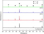
From the Figure 5, it is found that the SLM AlSi10Mg alloy is mainly composed of Al and Si phases. With the increase of annealing temperature, the content occupied by Si phase gradually increases and the content occupied by Al phase gradually decreases. After the annealing treatment, the diffraction peak corresponding to α-Al shows a slight shift to the left, and this shift increases with the increase of annealing temperature [21]. The reason for this shift is that in the SLM forming process, Si atoms are supersaturated and solidly dissolved in the Al matrix to form α-Al, i.e., the replacement solid solution. After annealing, the oversaturated Si atoms begin to gradually precipitate out of α-Al, which leads to a reduction in the lattice distortion caused by the replacement of Al atoms by Si atoms. Since the radius of Si atoms is smaller than the radius of Al atoms, this decrease in lattice distortion leads to a shift of the diffraction peaks to the left, making the lattice constant of the annealed α-Al larger than that of the as-deposited state [22]. As the annealing temperature increases, the precipitation of Si atoms is more favorable, and the resulting lattice distortion further decreases, and the lattice constant of α-Al increases accordingly, which leads to a further shift of the diffraction peaks corresponding to α-Al to the left. This indicates that the annealing treatment temperature has a significant effect on the lattice constant and diffraction peak position of the α-Al phase in SLM AlSi10Mg alloys.
3.2. Fatigue performance analysis
From the Figure 6 which it can be seen that the hardness of the SLM AlSi10Mg alloy decreases with increasing annealing temperature. The hardness of as-deposited state is 138 HV with a standard deviation of 5 HV. After annealing at 350°C, 400°C and 450°C, the hardness decreased by 38%, 51% and 58%, respectively. The hardness variation is closely related to the microstructure. Due to the rapid condensation during SLM forming, a large number of Si atoms are solidly dissolved in α-Al, forming a large number of reticulated eutectic Si, which produces an obvious solid solution strengthening effect, so the hardness of the as-deposited state is higher [23]. After annealing, the reticular eutectic Si completely disappears, and the Si phase precipitates from the α-Al phase, which makes the solid solution effect gradually weakened. As the annealing temperature increases, the fine Si particles gradually grow and the effect of fine-crystal strengthening is gradually weakened, so the hardness of the alloy gradually decreases with the increase of annealing temperature.

From Figure 7, it can be seen that the strength of the as-deposited state is the highest and the elongation is the worst. After annealing, the strength decreases and the elongation increases. As can be seen from Table 3, the tensile strength and yield strength of as-deposited is 433 MPa and 260 MPa. After annealing at 350°C, 400°C and 450°C, the tensile strength decreases by 55%, 58% and 71%, respectively; the yield strength decreases by 44%, 47%, and 67%, respectively. The elongation after annealing is significantly increased, the as-deposited state is 5.8%, the elongation increased by 107%, 174% and 241% at 350°C, 400°C and 450°C, respectively. The decrease in strength after annealing is mainly due to the weakening of solid solution strengthening. The supersaturated Si in the α-Al matrix gradually precipitates in the annealing process, resulting in solid solution strengthening gradually weakened until disappeared [24]. Secondly, with the increase of annealing temperature, the growth rate of Si phase accelerates, and the secondary Si particles in Al matrix are absorbed at the same time, resulting in a decrease in the number of small-sized Si particles and the overall density, thus weakening the precipitation strengthening effect of Si phase. In addition, the morphology change of eutectic Si also affects the strength. The dissolution and fracture of the reticulated eutectic Si after annealing weaken the hindering effect on dislocation slip, leading to a decrease in strength. The reason for the increase in plasticity can be attributed to the fact that the eutectic tissues in the sedimentary specimens are distributed among the α-Al dendrites in the form of a three-dimensional mesh, which exerts a cut-off effect on the matrix; on the other hand, the bonding between the eutectic tissues and the primary phases is weak, which makes them susceptible to fracture during tensile stretching. After annealing, the eutectic Si phase undergoes fragmentation and spheroidization, which reduces the cutting effect on the matrix. As the annealing temperature increases, the spheroidization degree of Si phase increases and the eutectic lattice is disrupted to a greater extent, resulting in improved plasticity. Also, the increase in annealing temperature leads to a decrease in the amount precipitated phases in α-Al matrix, which enhances the plastic deformability of the Al matrix. These factors together resulted in a significant increase in the elongation of the annealed specimens [25].

The fatigue cycle number of SLM AlSi10Mg alloy in the as-deposited state is 120391, and after annealing at 350°C, 400°C, and 450°C, the cycle number increases to 233451, 281928, and 349224, respectively, which is nearly 94%~190% higher than that of the as-deposited alloy. This indicates that annealing is conducive to the improvement of fatigue performance of the specimens [26]. The fatigue properties of SLM AlSi10Mg alloys are affected by many factors such as elongation, grain size and phase composition. There are a large number of reticulated eutectic Si phases in the deposited alloy, with small grains and many grain boundaries, so the material is not easy to deform when subjected to external forces, and the deformation of the matrix is not coordinated, resulting in poor fatigue performance of the material [27]. After 350°C, 400°C, 450°C annealing, the internal residual stress is reduced, the organization of coarsening, while the mesh eutectic Si phase dissolution, aggregation of the formation of different sizes of the bulk Si phase, by the external forces on the slip dislocation of the obstacle to reduce. At the same time, Si and Mg elements are precipitated from the α-Al matrix, and the reduction of Si and Mg elements increases the matrix plasticity and improves the fatigue performance of the material.
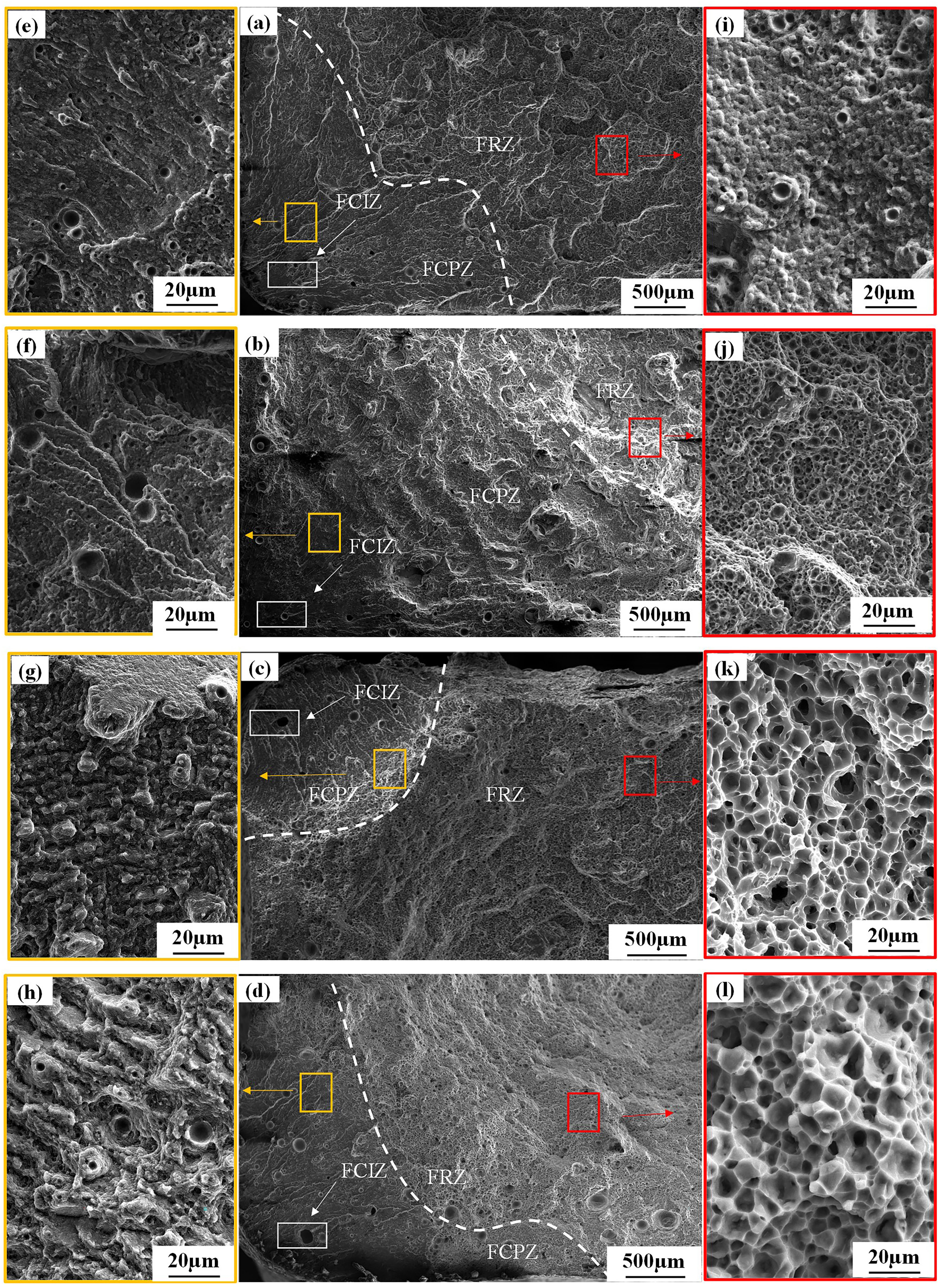
It is clearly seen in Figure 8 that the fatigue fracture of specimens in the as-deposited state and three annealed states is composed of the Fatigue Crack Initiation Zone (FCIZ), Fatigue Crack Propagation Zone (FCPZ) and Final Rupture Zone (FRZ) [28]. Although processes such as machining, polishing, and annealing can reduce surface roughness and associated notch effects, residual pores and defects within the alloy still dominate the fatigue failure mechanism. In the fatigue crack initiation zone (FCIZ), it is observed that all fatigue cracks initiate from gas pores at the specimen surface edges. These locations are prone to stress concentration, which accelerates crack initiation and propagation, ultimately leading to specimen failure. Concomitantly, the cracks propagate perpendicular to the direction of maximum stress, entering the crack propagation stage [29]. A large number of fatigue striations are observed in the fatigue crack propagation zone (FCPZ). This is attributed to the weak constraint of the alloy specimen surface on cyclic slip—once a fatigue crack initiates from the surface, it propagates rapidly, forming a river pattern along the fatigue crack propagation zone. The final rupture zone (FRZ) corresponds to the loss of strength in the remaining material and subsequent tensile fracture.

Fatigue fracture morphology of SLM AlSi10Mg alloy in the as-deposited state and three annealed states: (a) As-deposited state; (b) 350°C; (c) 400°C; (d) 450°C. FCPZ magnified views. (e) As-deposited state, (f) 350°C, (g) 400°C, (h) 450°C. FRZ magnified views. (i) As-deposited state. (j) 350°C, (k) 400°C, (l) 450°C.
Figure 8(e, f, g, h) shows the enlarged morphology of the fatigue extension zones of SLM AlSi10Mg alloy in the as-deposited state and three annealed states. The extended zone in the as-deposited state is mainly river-like and extends in all directions with the crack source as the center. After annealing at 350°C, the alloy starts to show more obvious fatigue strips, which are formed by plastic passivation of the specimen under cyclic stress loading, but the fatigue strips are in different directions and are more chaotic, indicating that the plasticity of the alloy is still not very good at this time. After annealing at 400°C, the fatigue strips become more regular, which indicates that the alloy’s plasticity at this time has been significantly improved. The annealing temperature is further increased to 450°C, the fatigue strips become finer and denser, indicating that the alloy has withstood more cycles and has better plasticity.
Figure 8(i, j, k, l) shows the enlarged morphology of the transient fracture zone of SLM AlSi10Mg alloy in the as-deposited state and three annealed states. It can be seen that the morphology of the transient fracture region is uneven compared to the fatigue crack extension region, and a large number of tough nests can be observed. In the as-deposited state, there are few and shallow tough spots, and the fracture mode is brittle fracture. After annealing at 350°C, there are more small and deeper pockets than in the as-deposited state, and after annealing at 400°C and 450°C, the pockets gradually become larger and shallower, the plasticity becomes better, and the fracture mode changes to ductile fracture.
3.3. Fatigue damage of SLM IN718 alloy based on apparent strain field characterization
In order to quantitatively study the fatigue damage behavior of SLM AlSi10Mg alloy and to establish the relationship between surface strain and fatigue damage, the surface strain of the alloy was collected by using the DIC technique, and the cloud images of the surface strain at different fatigue life stages were obtained as shown in Figure 9. The data collection area corresponds to the area of the gauge section, with dimensions of 6 mm in length and 3.5 mm in width. It is found that the deformation of SLM AlSi10Mg alloy is small and uniform at the beginning of fatigue. With the increase of fatigue times, the strain cloud image shows different color changes, and the specimen surface shows inhomogeneous deformation, and the degree of inhomogeneity deformation gradually increases. With the further increase of fatigue times, the degree of deformation also increases, and there is an obvious strain concentration region, i.e., the large deformation region. At this time, the SLM AlSi10Mg alloy begins to enter the rapid damage stage. When the large deformation region appears, the deformation of SLM AlSi10Mg alloy is mainly concentrated in the large deformation region, and the deformation of the rest region gradually stops. The degree of deformation in the large deformation region increases rapidly within a short cycle time, causing fatigue fracture of SLM AlSi10Mg alloy. It can be seen that the deformation trend of SLM AlSi10Mg alloy in the as-deposited state and the three annealed states is basically the same, and all of them show obvious large deformation regions, and the large deformation regions all appear at the proximal surface of the specimen. During the SLM forming process, holes and defects appear at the near-surface due to the uneven melting of the organization, and these holes and defects play a dominant role in the fatigue damage process.

Surface strain cloud image of SLM AlSi10Mg alloy in the as-deposited state and three annealed states: (a) As-deposited state, (b) 350°C, (c) 400°C, (d) 450°C.
Processing defects or internal pores in the specimens can induce stress concentration, forming local shear stress fields. During fatigue tests, differences in the elastoplastic response of the material lead to the superposition of microscale shear deformation, which ultimately manifests as a shear effect in the macroscopic DIC strain field [30].
SLM AlSi10Mg alloy accumulates damage under fatigue loading resulting in plastic deformation of the alloy until failure. In order to quantitatively study the fatigue damage evolution behavior of SLM AlSi10Mg alloy and to quantify the inhomogeneity of the surface deformation of the alloy, the average strain factor is introduced as a parameter to characterize the damage during the fatigue process of SLM AlSi10Mg alloy. The average strain factor is calculated by selecting 50 data point strains at equal intervals along the transverse and longitudinal directions in the large deformation region, and 1000 data point strains uniformly over the entire DIC observation area, as shown in the following equation:
Where: represents the average strain of 50 data points in the large deformation area for a certain number of cycles, and is the average strain of 1000 data points over the entire strain field for a certain number of cycles.
The greater the damage degree of SLM AlSi10Mg alloy, the greater its deformation inhomogeneity, the greater its average strain factor . Therefore, the average strain factor can reflect the fatigue damage characteristics of SLM AlSi10Mg alloy [31].
From the Figure 10, it is found that in the early stage of fatigue, the degree of deformation inhomogeneity of SLM AlSi10Mg alloy is very small, and when the number of cycles reaches a certain value, the localized strain concentration area appears, and the degree of deformation inhomogeneity of SLM AlSi10Mg alloy increases, the average strain factor increases rapidly with the increase in the number of cycles, and increases to a critical value in hundreds or thousands of cycles, resulting in fracture failure of SLM AlSi10Mg alloy. After annealing, the average strain factors at fatigue fracture are all increased substantially. As the annealing temperature increases, the average strain factor at fatigue fracture increases because the plasticity of the material increases after annealing, and the allowable plastic deformation under fatigue loading increases, so the average strain factor becomes larger.
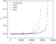
Variation of the average strain factor of SLM AlSi10Mg alloy in as-deposited and three annealed states with the number of cycles.
In order to make the study more relevant and sensitive to characterize the degree of plastic damage of SLM AlSi10Mg alloy. The average strain factor was normalized to define the DIC damage factor D in the following equation:
Where: is the maximum value of .
It is obvious that the value of damage factor D ranges from 0 to 1. When D = 0, it means that SLM AlSi10Mg alloy is in the initial state, and at this time no fatigue damage occurs in the alloy; when 0<D<1, SLM AlSi10Mg alloy is in the fatigue process, and the fatigue damage degree of SLM AlSi10Mg alloy increases with the increase of D; when D = 1, SLM AlSi10Mg alloy fatigue failure damage. Through the establishment of D, the expression transformation of fatigue damage from 0 to 1 is realized.
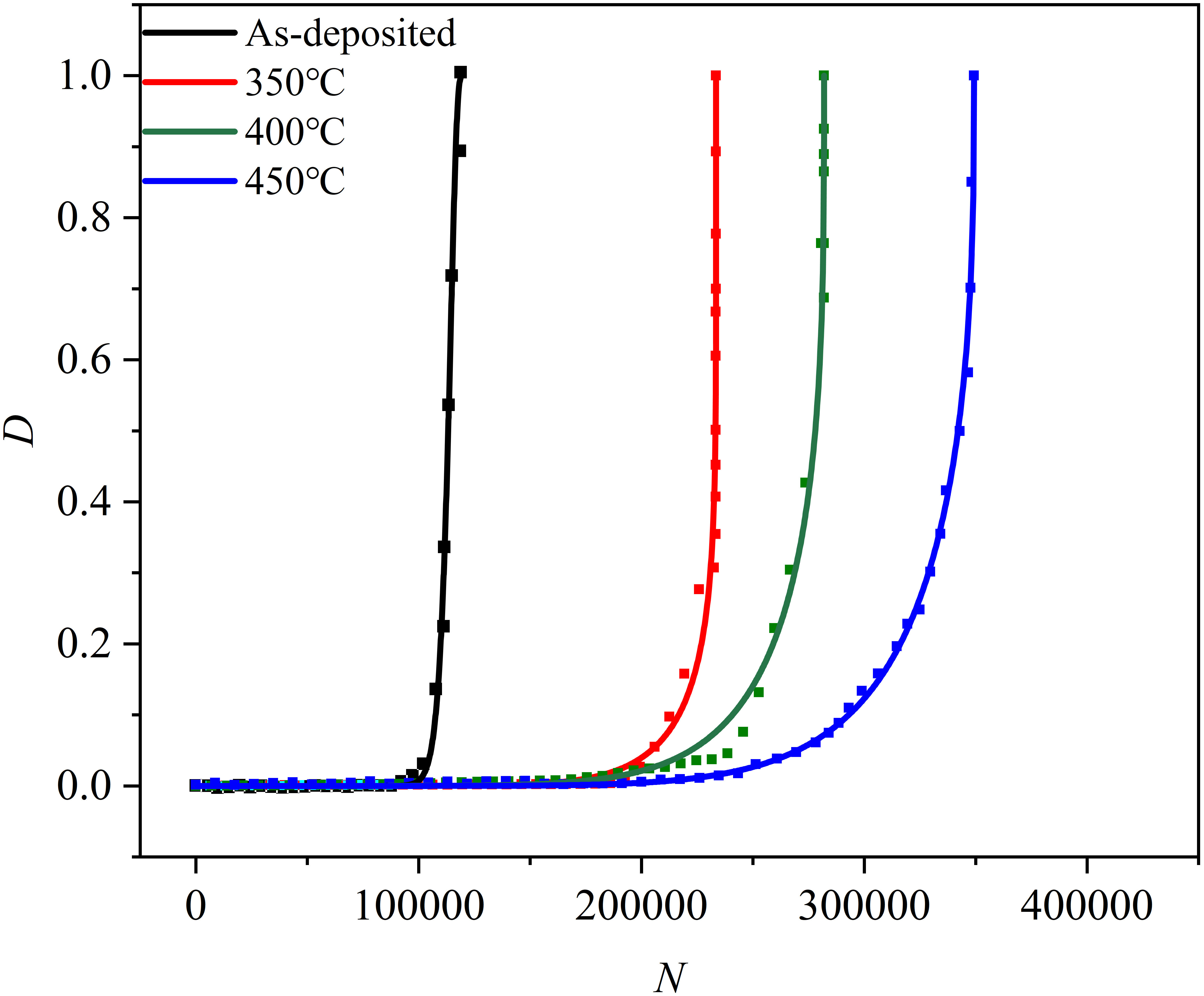
From the Figure 11, it can be seen that the fatigue damage of SLM AlSi10Mg alloy is mainly divided into two stages, one is the stable development stage, in which the damage of SLM AlSi10Mg alloy grows slowly and accounts for the main part of the fatigue life of SLM AlSi10Mg alloy, and the other one is the critical failure stage, in which the performance of SLM AlSi10Mg alloy deteriorates drastically and the damage increases significantly, which eventually leads to the fracture and damage of SLM AlSi10Mg alloy. The damage factor evolution curve of as-deposited is relatively rapid from the stable development stage to the critical failure stage. As the annealing temperature increases, the damage factor evolution curve from the stable development stage to the critical failure stage becomes smoother and smoother. The curvature of the damage factor fitting curve in Figure 11 is calculated to find the maximum curvature, which is defined as the critical damage factor Dc. When 0<D<DC, micro damage occurs in SLM AlSi10Mg alloy, and the damage grows slowly. When Dc<D<1, there is an obvious localized strain concentration in SLM AlSi10Mg alloy, and the alloy is seriously damaged, the surface deformation inhomogeneity is increase dramatically, and the damage degree also increases rapidly at this time.

From the Figure 12, it can be seen that the critical damage factors of the three annealed states have been greatly increased compared with that of the as-deposited state. The critical damage factor increases with the increases of annealing temperature. The larger the critical damage factor is, the stronger the ability of the material to resist fatigue breakage, and the better the fatigue performance of the material, which is the same as the results of the previous fatigue performance test of SLM AlSi10Mg alloy.

3.4. Comparison of the evolutionary pattern of damage factors of two models
It has been found [21] that the hardness of a material changes as the degree of damage to the material continues to increase. The degree of damage to the material can be characterized by the change in hardness.
where: HV0 is the initial hardness of the material when it is undamaged, and HV is the actual hardness of the material after being affected by the external load.
To make the comparative analysis easier, equation (3) is normalized so that the damage representation is transformed from 0 to 1. Define the damage factor De characterized by hardness:
where: HVf is the hardness of the material at fracture failure.
Figure 13 shows the variation of hardness with the number of cycles for as-deposited and three heat-treated SLM AlSi10Mg alloys. It can be observed from the figure that the trend of hardness change with the number of cycles is basically the same for both the as-deposited and the three heat-treated SLM AlSi10Mg alloys. The curves can be divided into three stages: an initial increase stage, a stable stage, and a rapid decrease stage. During the early stages of fatigue, the hardness exhibits a slight increase. As the number of cycles increases, the hardness begins to decrease and gradually stabilizes, with the material entering a steady development phase. Just before fatigue fracture, the hardness drops sharply before the specimen fractures. From a microscopic mechanism perspective, these results can be explained as follows: in the early stages of fatigue, the grains within the alloy undergo slip under the action of cyclic loading, resulting in hardening. Cyclic hardening enhances the material’s plastic deformation capability, causing an increase in hardness. As the number of fatigue cycles increases, the hardening effect spreads from local grains to the overall material, and the hardness stabilizes. In the later stages of fatigue, grain slip is obstructed, leading to the formation of slip bands, where intense localized plastic deformation causes local softening of the alloy and a sharp decrease in hardness [32]. After heat treatments at 350°C, 400°C, and 450°C, the hardening effect is reduced, the hardness of the SLM AlSi10Mg alloy decreases, and the decline in hardness before final fracture is slower. Moreover, the higher the heat treatment temperature, the more pronounced this phenomenon becomes.

Variation of the hardness of SLM AlSi10Mg alloy in the as-deposited state and three annealed states with the number of cycles.
As can be seen from the Figure 14, the fatigue damage of SLM AlSi10Mg alloy characterized by hardness is also divided into two stages: the stable development stage and the rapid damage stage. In the early fatigue stage, the alloy is in the stable development stage, the damage factor increases slowly and the alloy damage is small. When the alloy enters the rapid damage stage, the damage factor increases rapidly and the alloy fails. Taking the critical distinction between the stable development stage and the rapid damage stage as Dec.

From the Figure 15, it can be seen that the critical damage factors of the three annealed states have been increased substantially compared with that of the as-deposited state. As the annealing temperature increases, the critical damage factor increases. The larger the critical damage factor is, the stronger the ability of the material to resist fatigue breakage, and the better the fatigue performance of the material, which is consistent with the results obtained from the previous characterization with DIC.

From the Figure 16, it is found that the two damage factors have the same evolution trend with good consistency. Both are composed of two stages, stable development and rapid damage. With the increase in the number of cycles, there is an obvious critical value between the stable damage stage and the rapid damage stage, and it can be seen that the critical point of the DIC strain field damage evolution curve is later than the hardness damage evolution curve. This is due to the DIC strain field damage is based on the material surface point strain changes, while the hardness damage is based on the internal changes of the material, when the material damage occurs, the internal organization has been changed, the material properties change, but the surface non-uniform deformation degree has not yet changed, so the hardness characterization of the damage changes are more sensitive to the critical point of the earlier appearance. The advantage of the DIC strain field damage evolution is that it makes the damage evolution process become visualized through the strain cloud image. The two curves show the same trend, indicating that both methods are feasible to study fatigue damage evolution, with the hardness being more accurate and sensitive, and the apparent strain field method being more intuitive.

Comparison of evolutionary patterns of damage factors: (a) As-deposited state, (b) 350°C, (c) 400°C, (d) 450°C.
As described in References the fatigue damage analysis of the specimens was conducted by combining digital image correlation (DIC) and hardness measurements, respectively. This clearly reflects the relationship between fatigue damage and DIC as well as hardness, and both distinctly reveal the damage evolution behavior of the specimens. It also verifies the repeatability and reliability of the method proposed in this paper [33,34,35].
3.5. Fatigue damage modeling of SLM AlSi10Mg alloy
The fatigue damage evolution model is established by using Chaboche’s damage model [36], and the fatigue damage evolution law of SLM AlSi10Mg alloy is studied. The fatigue damage evolution equation of SLM AlSi10Mg alloy can be expressed as follows:
Where: f(D) is damage-characterizing function 或 damage-representing function;
σa is the average stress;
b, β are material parameters.
Regarding A, B argues that:
Substituting Equation (6) into Equation (5) yields the fatigue damage evolution equation (7):
Where: σa is the average stress;
b, α, β are material parameters;
N is the number of cycles.
According to the initial conditions N = 0, D = 0; at the time of destruction N = Nf , D = 1. Integration of equation (5) is obtained:
For convenience, we set, , then Equation (6) can be simplified as:
Where: a, c are coefficients related to the annealing temperature.
By applying Chaboche’s damage model to fit the damage factor D characterized by surface strain and the damage factor De characterized by hardness of SLM-fabricated AlSi10Mg alloy. The coefficients of the fatigue evolution equation (6) and fitting accuracy (R²) for SLM AlSi10Mg alloy derived therefrom are as follows in Table 4.
Coefficients of fatigue damage evolution equation for SLM AlSi10Mg alloy under two characterizations
It can be found that the fitted parameters a and c of the fatigue evolution equation for SLM AlSi10Mg alloy under both DIC characterization and hardness characterization are related to the annealing temperature, with a increasing with the annealing temperature and the parameter c decreasing with the increase of the annealing temperature [37, 38].
4. CONCLUSIONS
In this paper, the microstructure, mechanical properties and fatigue damage evolution behavior of SLM AlSi10Mg alloys at different annealing temperatures are investigated. The following conclusions are drawn:
-
(1)
SLM AlSi10Mg alloy consists of eutectic Si phase and supersaturated α-Al solid solution, the sedimentary state organization is a fine mesh structure; after annealing treatment, the organization undergoes obvious coarsening, and the smaller size Si particles gradually polymerize to form large size Si particles. As the annealing temperature increases, the grain size further increases, the strength decreases, the elongation increases, and the fatigue resistance increases. The as-deposited fracture mode is brittle fracture, and the annealed fracture mode is ductile fracture.
-
(2)
Using the Chaboche damage model to fit the damage factor, the fatigue damage evolution equations of SLM AlSi10Mg alloy based on the DIC apparent strain and hardness were established respectively, and the critical damage factor was obtained, which revealed the relationship between the strain and hardness of SLM AlSi10Mg alloy and the damage factor. The fatigue damage evolution laws of the DIC and hardness characterization are the similar, which consists of stable development stage and rapid damage stage. The critical inflection point of the damage evolution curve in the DIC strain field from the stable development stage to the rapid damage stage is later than that of the hardness damage evolution curve.
-
(3)
The higher the annealing temperature is, the later the damage factor rises rapidly and the later the damage deformation enters the rapid damage stage. The larger the critical damage factor, the stronger the material’s ability to resist fatigue breakage, and the better the fatigue performance of SLM AlSi10Mg alloy.
5. BIBLIOGRAPHY
- [1] ZOU, Y., WEI, Z., DU, J., et al, “Effect and optimization of processing parameters on relative density of AlSi10Mg alloy parts by selective laser melting”, Applied Laser, v. 36, n. 6, pp. 656–662, Dec. 2016.
-
[2] YAN, Q., SONG, B., SHI, Y., “Comparative study of performance comparison of AlSi10Mg alloy prepared by selective laser melting and casting”, Journal of Materials Science and Technology, v. 41, n. 6, pp. 199–208, Mar. 2020. doi: https://doi.org/10.1016/j.jmst.2019.08.049.
» https://doi.org/10.1016/j.jmst.2019.08.049 - [3] CHEN, K., XU, L., GAN, J., et al, “Effects of laser power on microstructure and mechanical properties of selective laser melted AlSi10Mg”, Jiguang Yu Guangdianzixue Jinzhan, v. 58, n. 13, pp. 347–355, Jul. 2021.
-
[4] CHEN, T., WANG, L., TAN, S., “Effects of vacuum annealing treatment on microstructures and residual stress of AlSi10Mg parts produced by selective laser melting process”, Modern Physics Letters B, v. 30, n. 19, pp. 1650255, Jul. 2016. doi: https://doi.org/10.1142/S0217984916502559.
» https://doi.org/10.1142/S0217984916502559 -
[5] XIAO, H., ZHANG, C., ZHU, H., “Effect of direct aging and annealing on the microstructure and mechanical properties of AlSi10Mg fabricated by selective laser melting”, Rapid Prototyping Journal, v. 29, n. 1, pp. 118–127, Jan. 2023. doi: https://doi.org/10.1108/RPJ-03-2022-0085.
» https://doi.org/10.1108/RPJ-03-2022-0085 - [6] WANG, Y., WANG, J., ZHANG, H., et al, “Effect of heat treatment on microstructure and mechanical properties of AlSi10Mg alloy produced by selective laser melting”, Acta Metallurgica Sinica, v. 57, n. 5, pp. 613–622, Apr. 2021.
-
[7] SAJADI, F., TIEMANN, J.M., BANDARI, N., et al, “Fatigue improvement of AlSi10Mg fabricated by laser-based powder bed fusion through heat-treatment”, Metals, v. 11, n. 5, pp. 683, Apr. 2021. doi: https://doi.org/10.3390/met11050683.
» https://doi.org/10.3390/met11050683 -
[8] YANG, L., XING, Y., “Experimental study on fatigue properties of Q420C steel welded joints at room temperature”, Latin American Journal of Solids and Structures, v. 19, n. 1, pp. e417, Oct. 2021. doi: https://doi.org/10.1590/1679-78256808.
» https://doi.org/10.1590/1679-78256808 -
[9] MATUŠŮ, M., DŽUBEROVÁ, L., PAPUGA, J., et al, “Fatigue analysis and heat treatment comparison of additively manufactured specimens from AlSi10Mg alloy”, International Journal of Fatigue, v. 185, pp. 108357, Aug. 2024. doi: https://doi.org/10.1016/j.ijfatigue.2024.108357.
» https://doi.org/10.1016/j.ijfatigue.2024.108357 -
[10] TRIDELLO, A., FIOCCHI, J., BIFFI, C.A., et al, “Effect of microstructure, residual stresses and building orientation on the fatigue response up to 109 cycles of an SLM AlSi10Mg alloy”, International Journal of Fatigue, v. 37, pp. 105659, Aug. 2020. doi: https://doi.org/10.1016/j.ijfatigue.2020.105659.
» https://doi.org/10.1016/j.ijfatigue.2020.105659 -
[11] CH, S., Raja, A., Jayaganthan, R., et al, “Study on the fatigue behavior of selective laser melted AlSi10Mg alloy”, Materials Science and Engineering A, v. 781, pp. 139180, Apr. 2020. doi: https://doi.org/10.1016/j.msea.2020.139180.
» https://doi.org/10.1016/j.msea.2020.139180 -
[12] WAN, H., WANG, Q., JIA, C., et al, “Multi-scale damage mechanics method for fatigue life prediction of additive manufacture structures of Ti-6Al-4V”, Materials Science and Engineering A, v. 669, pp. 269–278, Jul. 2016. doi: https://doi.org/10.1016/j.msea.2016.05.073.
» https://doi.org/10.1016/j.msea.2016.05.073 -
[13] YANG, C., ZHU, K., LIU, Y., et al, “A comparative study of fatigue energy dissipation of additive manufactured and cast AlSi10Mg alloy”, Metals, v. 11, n. 8, pp. 1274, Aug. 2021. doi: https://doi.org/10.3390/met11081274.
» https://doi.org/10.3390/met11081274 - [14] CAI, X., ZHANG, W., FAN, Z., et al, “Damage modes and response mechanisms of AlSi10Mg porous structures under different loading strain rates”, Acta Metallurgica Sinica, v. 60, n. 7, pp. 857–868, Jul. 2024.
-
[15] CHANDRA, V., CHAKRABORTY, P., “Automated crack extension measurement method for fracture and fatigue analysis using digital image correlation”, Engineering Fracture Mechanics, v. 305, pp. 110182, Jul. 2024. doi: https://doi.org/10.1016/j.engfracmech.2024.110182.
» https://doi.org/10.1016/j.engfracmech.2024.110182 - [16] TANG, P.J., YAN, T.Q., CHEN, B.Q., et al, “Effect of solution treatment on microstructure, tensile properties and residual stress of melted AlSi10Mg alloy in laser selection”, Materials & Design, v. 52, n. 2, pp. 155–163, Jan. 2024.
-
[17] ZHENG, Y., ZHAO, Z., XIONG, R., et al, “Effect of post heat treatment on microstructure, mechanical property and corrosion behavior of AlSi10Mg alloy fabricated by selective laser melting”, Progress in Natural Science, v. 34, n. 1, pp. 89–101, Feb. 2024. doi: https://doi.org/10.1016/j.pnsc.2024.02.001.
» https://doi.org/10.1016/j.pnsc.2024.02.001 -
[18] ABOULKHAIR, N., Maskery, I., Tuck, C., et al, “The microstructure and mechanical properties of selectively laser melted AlSi10Mg: the effect of a conventional T6-like heat treatment”, Materials Science and Engineering A, v. 667, pp. 139–146, Jun. 2016. doi: https://doi.org/10.1016/j.msea.2016.04.092.
» https://doi.org/10.1016/j.msea.2016.04.092 -
[19] WANG, C., HE, D., HE, C., et al, “Effect of heat treatments on microstructure and mechanical behavior of laser welded LPBF AlSi10Mg alloys”, Materials Today. Communications, v. 38, pp. 108478, Mar. 2024. doi: https://doi.org/10.1016/j.mtcomm.2024.108478.
» https://doi.org/10.1016/j.mtcomm.2024.108478 -
[20] LI, W., LI, S., LIU, J., et al, “Effect of heat treatment on AlSi10Mg alloy fabricated by selective laser melting: microstructure evolution, mechanical properties and fracture mechanism”, Materials Science and Engineering A, v. 663, pp. 116–125, Apr. 2016. doi: https://doi.org/10.1016/j.msea.2016.03.088.
» https://doi.org/10.1016/j.msea.2016.03.088 -
[21] KEMPF, A., HILGENBERG, K., “Influence of sub-cell structure on the mechanical properties of AlSi10Mg manufactured by laser powder bed fusion”, Materials Science and Engineering A, v. 776, pp. 138976, Mar. 2020. doi: https://doi.org/10.1016/j.msea.2020.138976.
» https://doi.org/10.1016/j.msea.2020.138976 -
[22] ZHUO, L., WANG, Z., ZHANG, H., et al, “Effect of post-process heat treatment on microstructure and properties of selective laser melted AlSi10Mg alloy”, Materials Letters, v. 234, pp. 196–200, Jan. 2019. doi: https://doi.org/10.1016/j.matlet.2018.09.109.
» https://doi.org/10.1016/j.matlet.2018.09.109 -
[23] SERT, E., HITZLER, L., HEINE, B., et al, “Influence of the heat treatment on the microstructure and hardness of additively manufactured AlSi10Mg samples”, Practical Metallography, v. 56, n. 5, pp. 91–105, Jan. 2019. doi: https://doi.org/10.3139/147.110560.
» https://doi.org/10.3139/147.110560 -
[24] LU, Q., XU, B., LIU, C., et al, “Interplay of heat treatment and deformation temperature on the microstructural evolution and mechanical behavior of SLM AlSi10Mg alloy”, Journal of Alloys and Compounds, v. 999, pp. 174995, Sep. 2024. doi: https://doi.org/10.1016/j.jallcom.2024.174995.
» https://doi.org/10.1016/j.jallcom.2024.174995 -
[25] KATTI, I., ZHANG, D., QIU, D., et al, “The effect of the iso-thermal heat treatment on the microstructure and properties of powder bed fusion-laser beam AlSi10Mg alloy”, Advanced Engineering Materials, v. 26, n. 12, pp. 2400202, Apr. 2024. doi: https://doi.org/10.1002/adem.202400202.
» https://doi.org/10.1002/adem.202400202 -
[26] LEHNER, P., BLINN, B., ZHU, T., et al, “Influence of the as-built surface and a T6 heat treatment on the fatigue behavior of additively manufactured AlSi10Mg”, International Journal of Fatigue, v. 187, pp. 108479, Oct. 2024. doi: https://doi.org/10.1016/j.ijfatigue.2024.108479.
» https://doi.org/10.1016/j.ijfatigue.2024.108479 -
[27] BAIG, S., GHIAASIAAN, R., SHAO, S., et al, “Tensile and fatigue behaviors of additively manufactured AlSi10Mg: effect of solutionizing and aging heat treatments”, Fatigue & Fracture of Engineering Materials & Structures, v. 46, n. 7, pp. 2662–2680, Jul. 2023. doi: https://doi.org/10.1111/ffe.14024.
» https://doi.org/10.1111/ffe.14024 -
[28] ZHANG, C., ZHU, H., LIAO, H., et al, “Effect of heat treatments on fatigue property of selective laser melting AlSi10Mg”, International Journal of Fatigue, v. 116, pp. 513–522, Nov. 2018. doi: https://doi.org/10.1016/j.ijfatigue.2018.07.016.
» https://doi.org/10.1016/j.ijfatigue.2018.07.016 -
[29] NGNEKOU, J.N.D., NADOT, Y., HENAFF, G., et al, “Fatigue properties of AlSi10Mg produced by additive layer manufacturing”, International Journal of Fatigue, v. 119, pp. 160–172, Feb. 2019. doi: https://doi.org/10.1016/j.ijfatigue.2018.09.029.
» https://doi.org/10.1016/j.ijfatigue.2018.09.029 -
[30] SONG, H., SUN, L., DU, J., “Effect of Pre-corrosion on the fatigue failure of additive manufactured AlSi10Mg alloy”, Journal of Materials Engineering and Performance, v. 31, n. 2, pp. 953–967, Sep. 2021. doi: https://doi.org/10.1007/s11665-021-06225-x.
» https://doi.org/10.1007/s11665-021-06225-x -
[31] LI, X., LI, L., ZHANG, L., et al, “Damage evolution behavior and damage constitutive model of selective-laser-melted Ti6Al4V alloy under different heat treatment temperatures”, Matéria (Rio de Janeiro), v. 29, n. 3, pp. e20240359, Sep. 2024. doi: https://doi.org/10.1590/1517-7076-rmat-2024-0359.
» https://doi.org/10.1590/1517-7076-rmat-2024-0359 - [32] YE, D.Y., WANG, D.J, “Variation characteristics of residual mechanical properties of 45# steel during fatigue damage”, Journal of Materials Research, v. 4, pp. 357–362, Oct. 1996.
-
[33] FREDRIK, B., DIMITRIOS, P., SUDATH, C.S., “Hardness measurements as a technique for measuring accumulated fatigue damage”, International Journal of Structural Integrity, v. 13, n. 4, pp. 699–716, Jul. 2022. doi: https://doi.org/10.1108/IJSI-04-2022-0061.
» https://doi.org/10.1108/IJSI-04-2022-0061 -
[34] SONG, H., REN, J., JIANG, S., et al, “Fatigue damage evolution and failure mechanism in pre-corroded AlSi10Mg fabricated by laser powder bed fusion”, Engineering Fracture Mechanics, v. 317, pp. 110926, Mar. 2025. doi: https://doi.org/10.1016/j.engfracmech.2025.110926.
» https://doi.org/10.1016/j.engfracmech.2025.110926 -
[35] ROJAS-ARIAS, N., UNTI, L., Valim, D.B., et al, “Microstructural evolution of PBF-LB AlSi10Mg under different heat treatment conditions”, Materials Research, v. 28, pp. e20250146, Apr. 2025. doi: https://doi.org/10.1590/1980-5373-mr-2025-0146.
» https://doi.org/10.1590/1980-5373-mr-2025-0146 -
[36] CHABOCHE, J.L., “A review of some plasticity and viscoplasticity constitutive theories”, International Journal of Plasticity, v. 24, n. 10, pp. 1642–1693, Oct. 2008. doi: https://doi.org/10.1016/j.ijplas.2008.03.009.
» https://doi.org/10.1016/j.ijplas.2008.03.009 -
[37] SONG, H., LIU, C., ZHANG, H., et al, “A DIC-based study on fatigue damage evolution in pre-corroded aluminum alloy 2024-T4”, Materials (Basel), v. 11, n. 11, pp. 2243–2243, Nov. 2018. doi: https://doi.org/10.3390/ma11112243. PubMed PMID: 30423895.
» https://doi.org/10.3390/ma11112243 -
[38] ZHAO, G., Liu, Y.F., Jiang, Y.Z., et al, “Analysis on high cycle fatigue properties and fatigue damage evolution of TC25 titanium alloy”, Key Engineering Materials, v. 697, pp. 658–663, Jul. 2016. doi: https://doi.org/10.4028/www.scientific.net/KEM.697.658.
» https://doi.org/10.4028/www.scientific.net/KEM.697.658