 Evaluating reality capture technologies for structural joint verification in prefabricated concrete assemblies
ABSTRACT
Prefabricated concrete construction demands precise dimensional accuracy at structural joints for safety and performance; therefore, reliable as-built verification is required for construction quality assurance. A joint-level BIM-aligned ground-truth-validated framework was developed to quantitatively compare terrestrial LiDAR and UAV-based photogrammetry for structural joint verification in prefabricated concrete assemblies. A full-scale prefabricated concrete mock-up was surveyed using both sensing modalities, and point clouds were registered to a BIM reference model. Deviation heatmaps, node-level errors, local point density metrics, longitudinal deviation profiles, and acquisition-plus-processing time requirements were derived. LiDAR was shown to provide highly accurate mapping, with over 85% of surface points within ±1 mm of BIM geometry and joint mean deviations of 1.8–3.2 mm, whereas photogrammetry exhibited joint mean deviations of 2.5–6.7 mm, with some local peaks up to +5 mm. Using independently validated accuracy bounds and effort trade-offs that support method selection for prefabricated construction projects, this framework was shown to advance QA/QC practice by enabling tolerance-focused scan-to-BIM verification in connection-critical regions.
Keywords:
LiDAR; scan-to-BIM; BIM accuracy; deviation analysis
1. INTRODUCTION
Prefabricated concrete construction plays a central role in delivering buildings and infrastructure rapidly, while maintaining tight dimensional tolerances at structural joints. Building information modeling (BIM) provides a detailed digital representation of these components and their intended connections, and is widely used as the primary reference for design coordination and quality assurance [1]. When prefabricated beams, columns, and wall panels are assembled on-site, even millimeter-scale deviations from the BIM model at node connections can influence structural performance, cladding alignment, and serviceability [2]. Manual surveys with tapes, levels, and total stations have been used to check these interfaces; however, such procedures are labor-intensive and often focus on a limited set of discrete points rather than on full three-dimensional joint geometry. The growing demand for industrialized construction, combined with rising expectations for traceable quality control, has encouraged the adoption of reality capture technologies that create dense as-built point clouds for direct comparison with BIM models [3].
A broader set of application scenarios was clarified to demonstrate how prefabricated components can be supported by BIM-referenced reality capture beyond a single experimental mock-up. Dimensional verification can be performed at the pre-delivery stage for beams, columns, wall panels, and slab interfaces to confirm conformance to the BIM reference before transport, and trial-fit assembly checks can be conducted to detect cumulative tolerance stack-up at the beam–column and panel–panel interfaces. During erection, joint seating conditions, alignment of bearing regions, and interface continuity can be assessed by direct point-cloud-to-BIM deviation mapping, whereas post-installation checks can be extended to façade alignment, slab elevation continuity, and opening placement [4]. For large- or difficult-access site layouts, rapid exterior capture can be supported by aerial photogrammetry when centimeter-level documentation is acceptable, whereas tolerance-critical joint verification can be supported by terrestrial LiDAR when millimeter-level bounds are required. A structured linkage between these scenarios and the selection logic is provided (Table 1) to explicitly recognize the workflow’s practical value and wide-ranging applicability.
Application scenarios for BIM-referenced reality capture in prefabricated concrete projects and corresponding recommended workflows.
Terrestrial LiDAR scanning and UAV-based photogrammetry have emerged as the two leading approaches for capturing three-dimensional as-built data on construction sites. LiDAR instruments emit laser pulses and record their return times, producing dense point clouds with millimeter-scale ranging accuracy that remain largely insensitive to ambient lighting. UAV-based photogrammetry acquires overlapping images from drone-mounted cameras and reconstructs the geometry using structure-from-motion and multi-view stereo algorithms, delivering rich color information at relatively low equipment cost and efficiently covering large areas [5].
Higher accuracy and stability have been attributed to active ranging, which captures dense geometry with limited dependence on surface texture or ambient lighting, and closer agreement with ground-truth measurements has been demonstrated at the connection nodes. More uniform sampling has been evidenced by higher local point density at joint regions, which have stabilized deviation fields and resolved millimeter-scale offsets more consistently [6]. Efficiency and cost-effectiveness have been framed using acquisition-effort indicators rather than monetary pricing, and predictable processing demand has been documented for LiDAR relative to photogrammetric reconstruction workloads as the project scale has increased. In contrast, wider area coverage and lower equipment cost have been supported by photogrammetry, while greater sensitivity to occlusion, shadowing, and texture has been reflected in larger deviation variability along the structure [7].
Previous applications in construction and related fields used LiDAR for precise scan-to-BIM alignment and deformation monitoring, whereas photogrammetry supported progress-tracking and documentation tasks in which centimeter-level accuracy was sufficient [8]. These studies demonstrate the potential of both methods. Usually, they addressed either LiDAR or photogrammetry in isolation or evaluated performance at the level of global building geometry and surface representation rather than at the critical structural joints that govern prefabricated assembly quality.
Quality assurance in prefabricated concrete systems requires robust evidence that beam–column and panel–panel interfaces meet stringent tolerance limits, not only in average offsets but also in local deviations, point cloud completeness, and measurement stability along the building axis. Previous comparative investigations between LiDAR and photogrammetry often relied on simple distance statistics, qualitative visual assessments, or site-wide deviation ranges, without explicitly focusing on individual joints or systematic benchmarking across different project scales [9]. Only limited work has aligned both LiDAR and photogrammetric point clouds to a common BIM reference and interrogated tolerance compliance at specific nodes using joint-level deviation maps, point density analysis, and independent ground-truth measurements [10]. The time and cost implications of each sensing strategy for small, medium, and large prefabricated projects have rarely been quantified in a unified framework, and guidance on selecting between LiDAR, photogrammetry, or hybrid workflows for joint verification remains fragmented. This combination of missing joint-focused accuracy evidence, incomplete multimetric comparison, and lack of structured method selection guidance formed the central knowledge gap addressed by the present investigation [11].
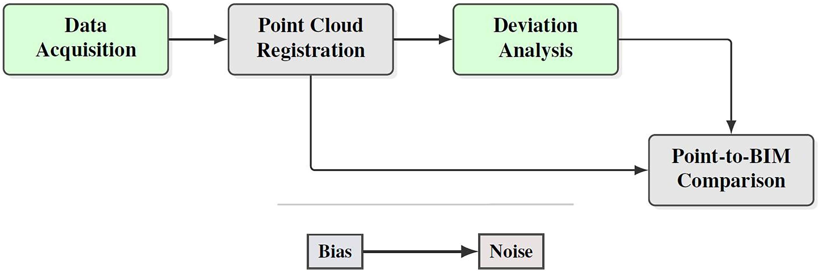
This study addresses this gap by designing a comprehensive evaluation of terrestrial LiDAR scanning and UAV-based photogrammetry on a prefabricated concrete mock-up that incorporates representative beams, columns, wall panels, and slab connections. Both sensing methods were applied to the same testbed. Their point clouds were aligned to a reference BIM model, and joint-level deviation heatmaps, point cloud density distributions, and as-built versus BIM overlays were derived at critical node regions. Node-wise deviations from both methods were compared with ground-truth measurements, deviation profiles were examined along the length of the structure, and field and processing times were benchmarked across project scales ranging from single-module assemblies to larger aggregated configurations [12]. The analysis was extended to indoor and outdoor scanning conditions and culminated in a decision framework that linked precision requirements, project scale, and interior coverage to determine whether LiDAR, photogrammetry, or a hybrid approach was appropriate. Therefore, the objectives of this study are as follows: the investigation aimed to establish a BIM-integrated framework for quantitatively comparing terrestrial LiDAR scanning and UAV-based photogrammetry for structural joint verification in prefabricated concrete assemblies (Figure 1), and to define the circumstances under which each technology, or their combination, provided the most reliable and efficient support for construction quality control [13].
A comprehensive comparative evaluation of terrestrial LiDAR scanning and UAV-based photogrammetry was conducted on a prefabricated concrete mock-up that incorporated representative beams, columns, wall panels, and slab connections [14]. Both sensing modalities were applied to a common testbed, and BIM-referenced verification was enabled by consistently aligning the as-built datasets with the design model. Joint-focused geometric performance, overall deviation behavior, and workflow effort have been assessed using a unified set of indicators, and the results have been consolidated into a decision framework that links precision demands, project scale, and interior coverage and needs to be appropriately selected among LiDAR, photogrammetry, or hybrid strategies [15]. Therefore, the objective of this study was to establish a BIM-integrated basis for quantitatively comparing these reality-capture technologies for structural joint verification, and to identify the conditions under which each approach, or their combination, can be applied most effectively for construction quality control [11].
2. MATERIALS AND METHODS
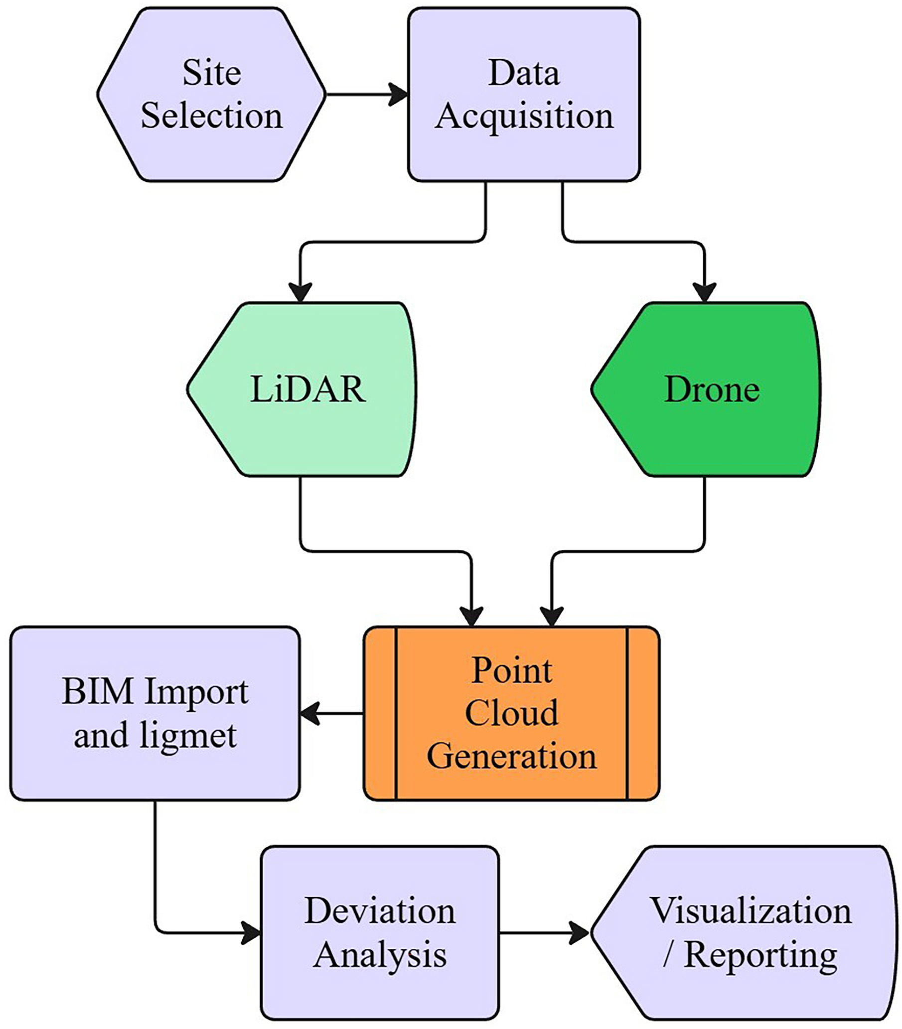
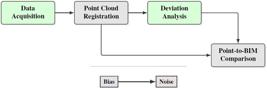
This study was designed as a controlled comparative evaluation of terrestrial LiDAR and UAV-based photogrammetry for the geometric quality assessment of prefabricated concrete assemblies within a BIM-referenced workflow. A full-scale mock-up of a prefabricated concrete structure was constructed and used to generate the as-built datasets. Both sensing modalities were applied to this common testbed, and the resulting point clouds were processed and aligned to a common BIM reference model to enable a direct comparison of geometric accuracy, data completeness, and acquisition effort. The methodological sequence comprised the preparation of the prefabricated testbed and BIM model, data acquisition using LiDAR and UAV-based photogrammetry, point cloud processing, BIM-based alignment, and the derivation of geometric metrics. The sequence is shown in Figure 2.

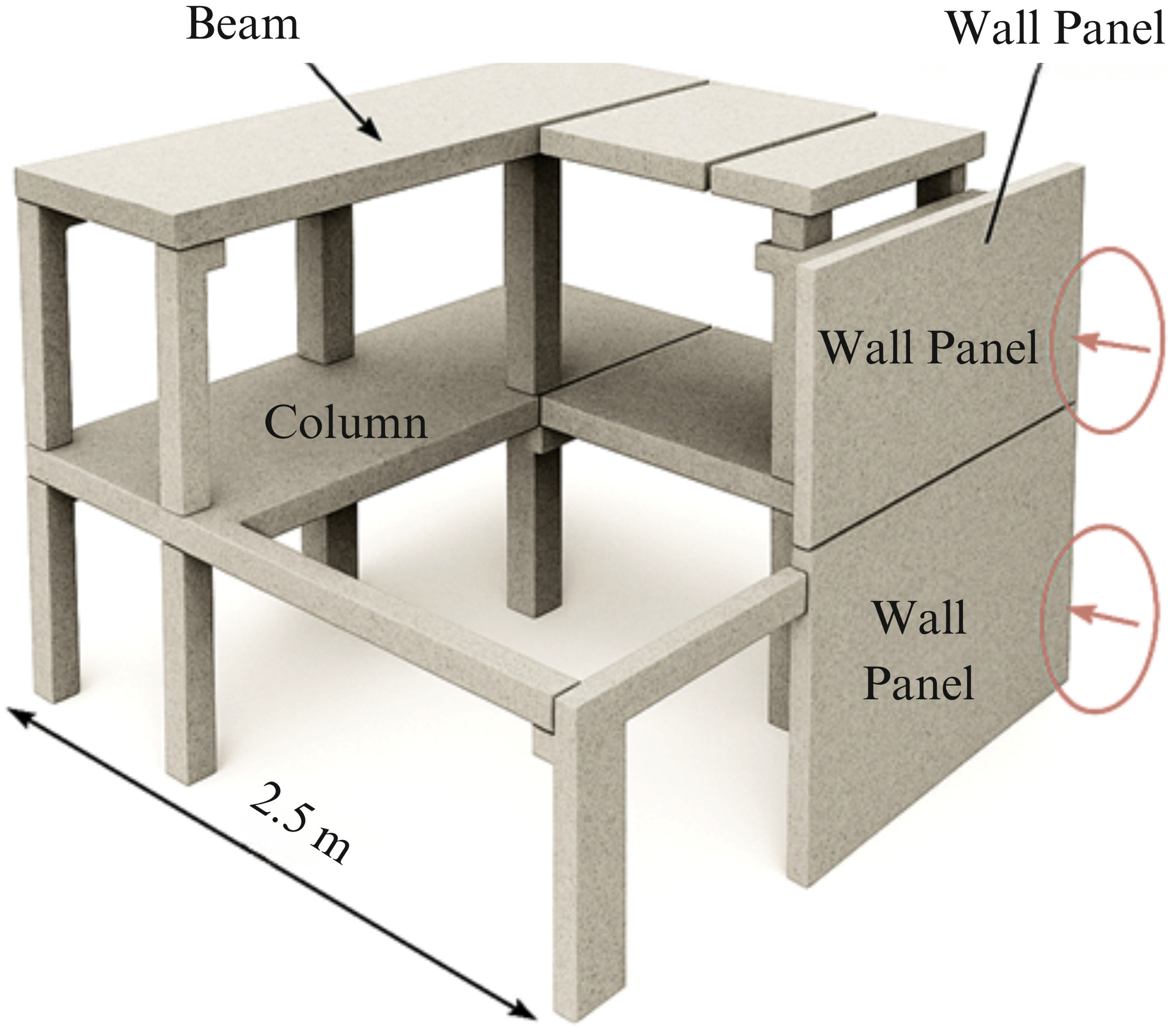
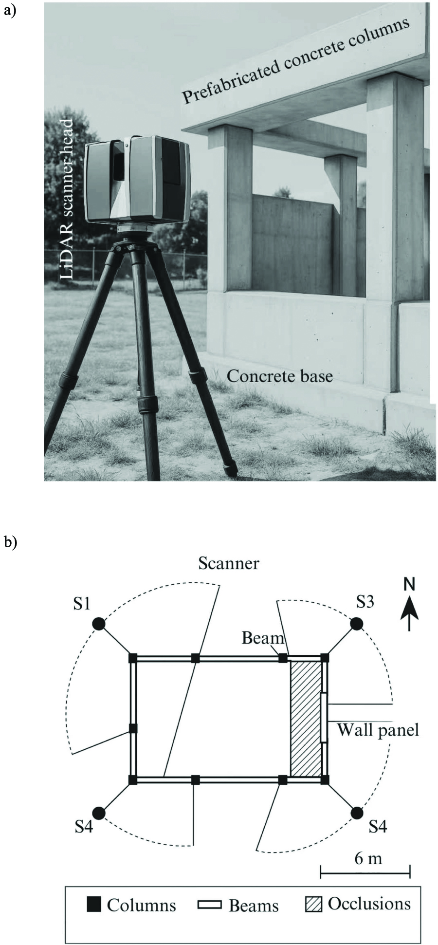
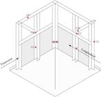
The experimental testbed consisted of a prefabricated concrete mock-up designed to capture the key geometric and connection characteristics of modular concrete construction. The configuration includes reinforced concrete columns, beams, wall panels, and slab elements. Beam–column dry joints and tongue-and-groove wall panel interfaces were incorporated to represent locations where geometric deviations were likely to influence the assembly performance [16]. The mock-up was positioned in an open outdoor yard to allow access around the perimeter for both terrestrial and aerial surveys, and clearance was maintained to accommodate the scanner tripod locations and UAV flight paths. A BIM assembly model, referenced to a local site coordinate system, was used as the design baseline for all deviation analyses. The physical arrangement of the mock-up and the principal geometric features are illustrated in Figure 3.
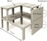
Experimental setup for the prefabricated concrete mock-up used as the testbed for LiDAR and UAV-based photogrammetry.
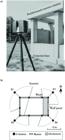
Terrestrial LiDAR data was acquired using a Faro Focus S350 terrestrial laser scanner. The instrument characteristics include the device type, range precision, field of view, and data rate. The scanner was mounted on a tripod and placed at several locations around the mock-up at standoff distances to ensure coverage of all external faces with limited occlusion. Individual scans were performed at a resolution setting targeting a point spacing of approximately 5 mm on the concrete surfaces, within typical ranges. Vertical and horizontal rotation limits were set to exploit the instrument’s angular range, and integrated compensators and calibration routines were employed according to the manufacturer’s recommendations [17]. At each station, a full 360° scan was performed, and the signal returns from reflective surfaces, such as glazing and metal fixtures, were retained for subsequent filtering. Photographic documentation of the scanner and field layout are presented in Figure 4.
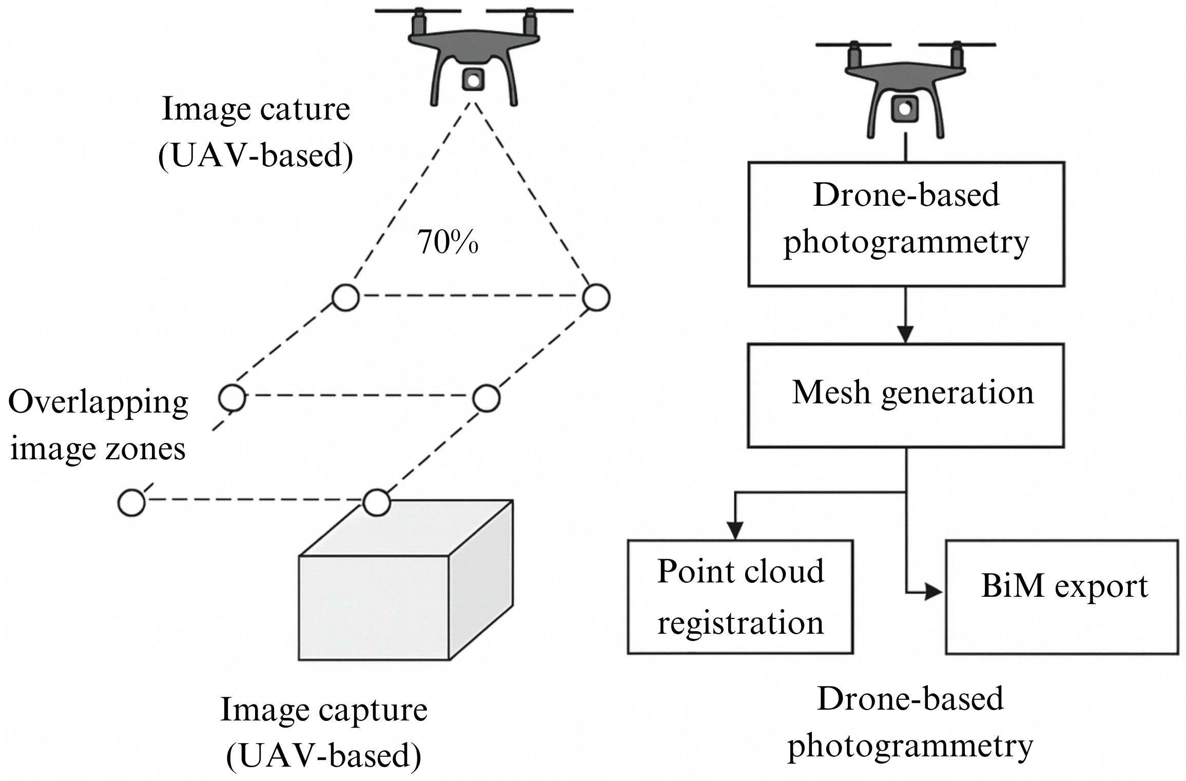
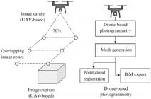
UAV-based photogrammetric datasets were collected using a DJI Phantom 4 RTK platform equipped with a 20-megapixel RGB camera and a global shutter sensor. The main camera and platform parameters, including sensor resolution, lens field of view, and data recording rate, are listed in Table 2. Flight missions were planned to achieve a high image overlap and a consistent ground sampling distance across the surfaces of interest [18]. A sequence of parallel flight lines was flown around the mock-up at a fixed altitude, combined with oblique viewing angles directed toward the vertical faces of the structure, to capture the joint regions and recessed details. A forward and side overlap of at least 70% was targeted, and the UAV used real-time kinematic positioning to record camera centers with centimeter-level georeferencing accuracy. Image exposure and shutter speed settings were adjusted prior to each mission based on ambient illumination. The UAV-based acquisition configuration and the flight path concept are shown in Figure 5.
(a) UAV-based photogrammetry capture configuration, (b) indicative flight paths around the prefabricated concrete mock-up.
All reality capture campaigns supporting the analyses in this study were conducted outdoors around the prefabricated concrete mock-up. The environmental conditions during these campaigns were recorded to contextualize the potential sources of measurement noise. Ambient temperature, wind speed, sunlight intensity, sky conditions, and visually identified interference sources, such as glare from metal or reflections on glass, are documented and reported in Table 3. Indoor scanning trials using the same LiDAR and UAV-based systems were conducted in a separate experimental program on a similar mock-up under controlled lighting; however, their procedures and outcomes formed part of a distinct study. Panoramic indoor scanning in the presence of obstacles was achieved through a multistation 360° acquisition strategy, treating occlusion as a coverage-planning constraint rather than a post-processing artifact. Scan stations were distributed to bracket major obstacles, and sufficient overlap between adjacent views was ensured to minimize shadow zones behind the beams, panels, and temporary supports. Elevated tripod extensions and dual-height scans were employed so that the line-of-sight to recessed joint faces was increased, and tilted scans were applied where permitted by the scanner’s vertical field of view. Registration robustness was improved by the placement of checkerboard targets and by the reuse of prominent geometric features across stations, after which cloud-to-cloud registration and iterative closest point refinement were performed to enforce closure consistency. Coverage adequacy was verified through residual checks at the control features and through joint-centered point-density inspection.
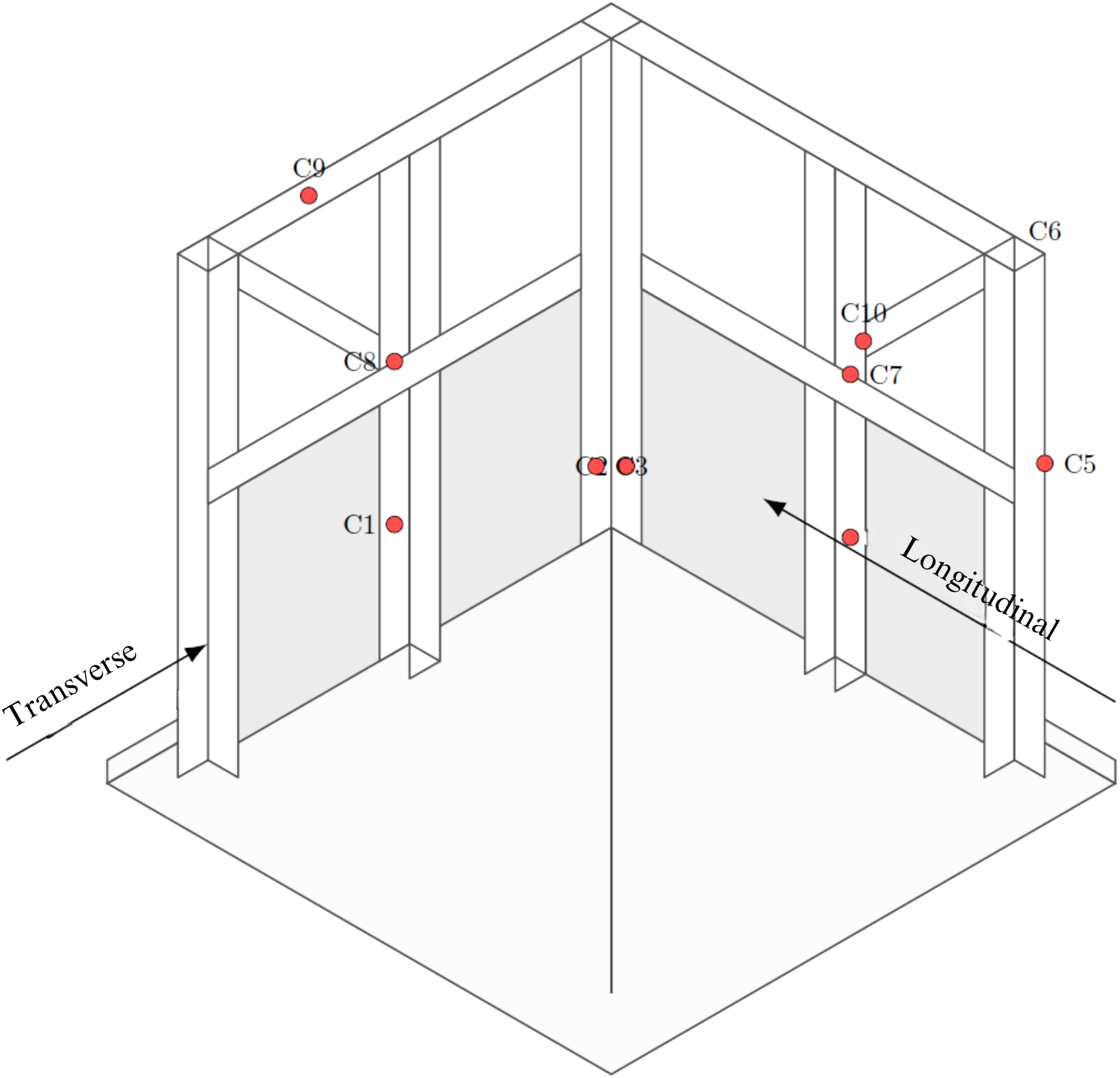
A purposive sample of ten joint locations (C1–C10) was adopted to ensure that joint-scale performance could be evaluated across repeated connection archetypes while remaining compatible with the practical constraints of total-station benchmarking and joint-centered point-density extraction. Coverage was therefore distributed across the connection geometries represented in the mock-up, so that variability introduced by occlusion, re-entrant corners, and surface texture could be captured within a manageable, traceable design, as contextualized.To avoid redundancy, software-specific workflow descriptions were consolidated into a single, modality-parallel pipeline and the methodological narrative was restricted to parameter choices that materially affect alignment quality and deviation estimation, with the sampling structure and indicator-to-dataset mapping being summarised in Table 4. In addition, indoor trials were excluded from the present analyses because they were executed under a distinct experimental program with controlled lighting and operational conditions that were not comparable to the outdoor campaigns reported, which was explicitly defined as a limitation because interior environments may yield different photogrammetric stability and LiDAR occlusion patterns. Therefore, the need for dedicated indoor validation was reserved for future work.
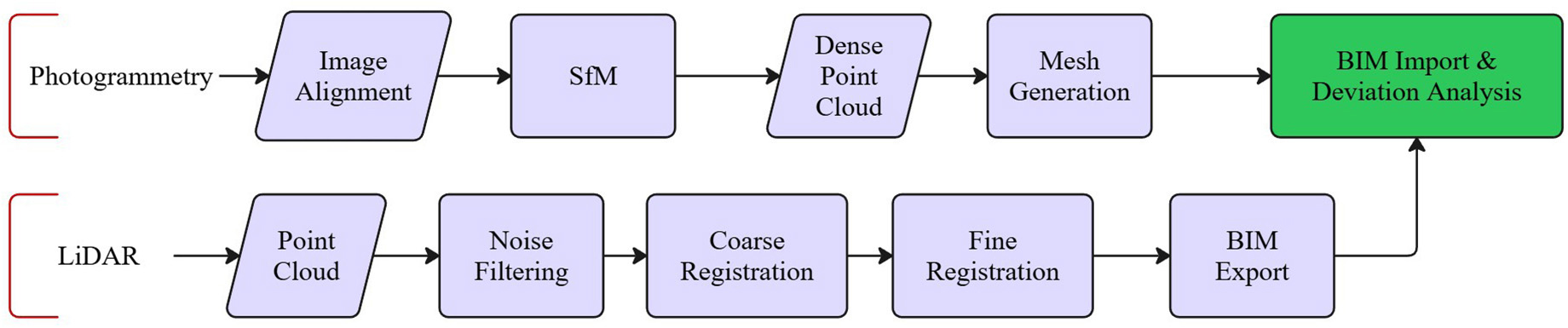
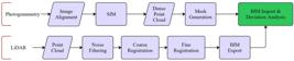
Post-capture processing of LiDAR data was performed using dedicated point-cloud software supplied with the scanner. Individual scans were first filtered for noise to remove isolated returns, sky points, and outliers. The remaining data were registered into a unified coordinate system using a combination of target-based alignment and cloud-to-cloud registration with checkerboard targets and prominent geometric features employed as tie elements between adjacent scans. Registration quality was verified by inspecting residuals at the control targets and visually inspecting the overlap regions. The resulting consolidated point cloud was exported to the LAS format. The main stages of this processing sequence are illustrated in Figure 6.
Point cloud processing pipeline for LiDAR and UAV-based photogrammetry, from raw data acquisition to unified, filtered point clouds.
Photogrammetric image processing was performed using structure-from-motion and dense multiview stereo workflow. The acquired images were first imported into the photogrammetry software, and the camera calibration parameters were initialized using the UAV platform’s sensor model. Feature detection and matching were applied to overlapping image pairs, and a sparse point cloud and initial camera poses were estimated through a bundle adjustment. The recorded RTK positions of the camera centers were used to assist georeferencing and constrain the solution within a consistent coordinate system. A dense reconstruction was then generated from the calibrated image set, followed by mesh creation and point cloud extraction at a resolution compatible with LiDAR point density. Spurious points, vegetation, and ground clutter were removed by using a combination of automated classification tools and manual editing. The final photogrammetric point clouds were exported in the PLY format. The complete processing pipeline for both LiDAR and photogrammetry is shown in Figure 5.
BIM referencing of the processed point clouds was performed using Autodesk ReCap and NavisWorks. The BIM model of the prefabricated assembly was imported and set as the primary reference, and both the LiDAR and photogrammetric point clouds were aligned to this model. An initial rough alignment was achieved by manually matching identifiable architectural and structural features, such as column bases and beam corners, between the point clouds and the BIM geometry. This was followed by fine registration using an iterative closest point algorithm, which refined the rigid-body transformation and ensured that the as-built data and design model shared a common coordinate frame. The alignment quality was checked using residual statistics at control features and by visual inspection of overlay views that display the point cloud and BIM model simultaneously. The BIM alignment procedure and the key reference elements involved in the transformation are illustrated in Figure 7.
BIM-to-point cloud alignment procedure used to register LiDAR and photogrammetric datasets to the prefabricated concrete BIM model.
After alignment, geometric quality metrics were consistently derived from the point clouds for both sensing modalities. Deviation maps were generated by computing the signed shortest distance from each point in the as-built cloud to its corresponding surface in the BIM model, yielding dense fields of point-to-model offsets across the structural elements. Local coordinate systems were established at critical joints, such as beam–column nodes and panel–panel interfaces, and deviation values within predefined neighborhoods were extracted for statistical analysis [19]. The point cloud density at the joint regions was quantified by projecting points within a specified radius onto a local reference plane and counting points per unit area in sliding windows centered on the joint. Selected connection points were also surveyed directly using high-precision total station measurements to provide ground-truth coordinates, and deviations derived from the LiDAR and photogrammetric point clouds at these locations were compared with the reference coordinates to assess the measurement accuracy. Longitudinal reference lines were defined along the building axis through the centroids of successive columns and beams in the BIM model, and offsets of corresponding features in the as-built point clouds were sampled along these lines to characterize global positional deviations. The capture and processing times for each sensing modality were recorded separately for data acquisition, point cloud generation, registration, and BIM alignment, enabling the interpretation of geometric quality metrics in relation to the effort required to obtain them [20].
The assessment indicators were grouped into geometric accuracy, data completeness, and acquisition effort; their definitions are summarized in Supplementary Table 1. The geometric accuracy at local joints was quantified through signed point-to-surface distances between the registered point clouds and the corresponding BIM elements, which were computed and visualized as deviation heatmaps in Autodesk ReCap and Navisworks. Node-level accuracy indicators were obtained by sampling these distances at the ten predefined connection points and comparing them with the coordinates measured with a total station in the same software environment. Data completeness indicators were calculated as point density per unit area in joint-centered windows, derived directly from the LiDAR and photogrammetric point clouds in Faro SCENE and dedicated photogrammetry processing software. Global alignment indicators along the longitudinal axis were produced by extracting offsets between BIM reference lines and associated as-built points in Navisworks. Acquisition effort indicators consisted of field acquisition and processing times for registration, reconstruction, and BIM integration, which were logged separately for each technology during the study [21]. These prescriptions establish a traceable mapping between each indicator, the underlying dataset, the computational steps, and the software environment used for its derivation.
3. RESULTS AND DISCUSSION
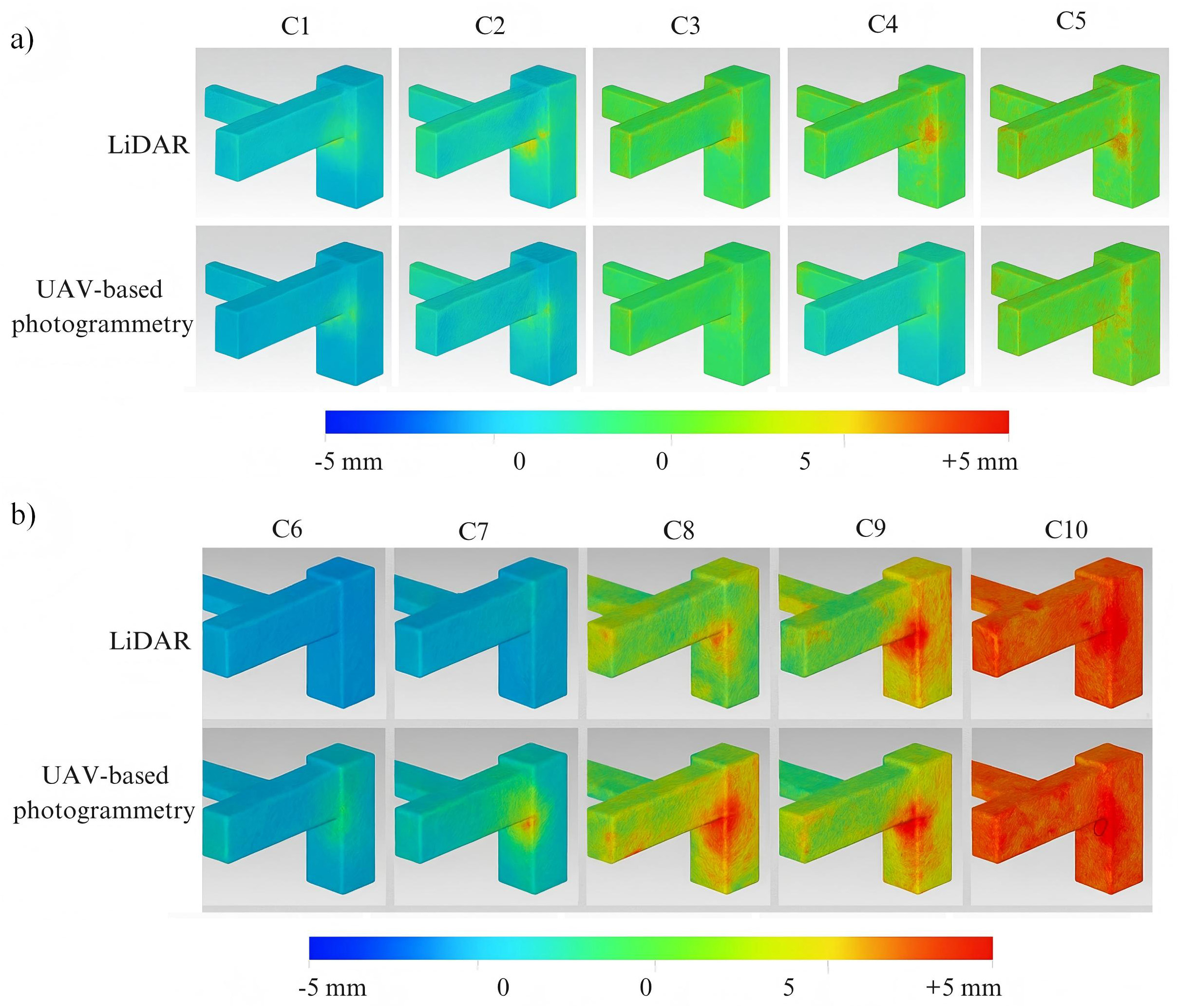
Figure 8 illustrates the behavior of joint-level deviation fields when the as-built geometry is registered to the BIM reference across ten beam–column connections (C1–C10), with signed offsets reported within a ±5 mm band. The LiDAR-based maps indicate that smaller departures were sustained at C1–C4 and C6–C7, and the measured offsets were primarily confined to a few millimeters, which is consistent with dense active ranging that preserved surface continuity at the re-entrant corners and bearing interfaces [22]. Larger localized departures were observed at C5 and C8–C10, and the deviation magnitude approached the +5 mm bound at specific faces, suggesting that placement error and element-to-element fit-up governed the dominant geometric response at these nodes rather than registration drift [23]. The UAV-photogrammetry maps exhibit spatially heterogeneous deviation fields across most joints, and amplified localized departures are indicated near edges and recessed regions, where occlusion reduces multiview ray intersection quality and where limited surface texture and illumination nonuniformity degrade feature matching and bundle adjustment stability. These mechanisms imply that photogrammetry error propagation is controlled by imaging geometry and surface appearance, whereas LiDAR error is dominated by comparatively stable instrument and registration components [24]. These results suggest that tolerance verification at prefabricated joints is better supported by LiDAR when the millimeter-level acceptance criteria are enforced. In contrast, photogrammetry is better positioned for contextual coverage or hybrid workflows that use LiDAR-constrained anchors and joint-focused filtering to suppress reconstruction noise and stabilize deviation estimation at critical interfaces [25].
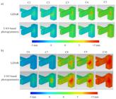
(a-b) Joint-scale signed deviation heatmaps (−5 to +5 mm) between BIM surfaces and as-built point clouds at ten prefabricated beam–column joints (C1–C10) obtained using terrestrial LiDAR and UAV-based photogrammetry.
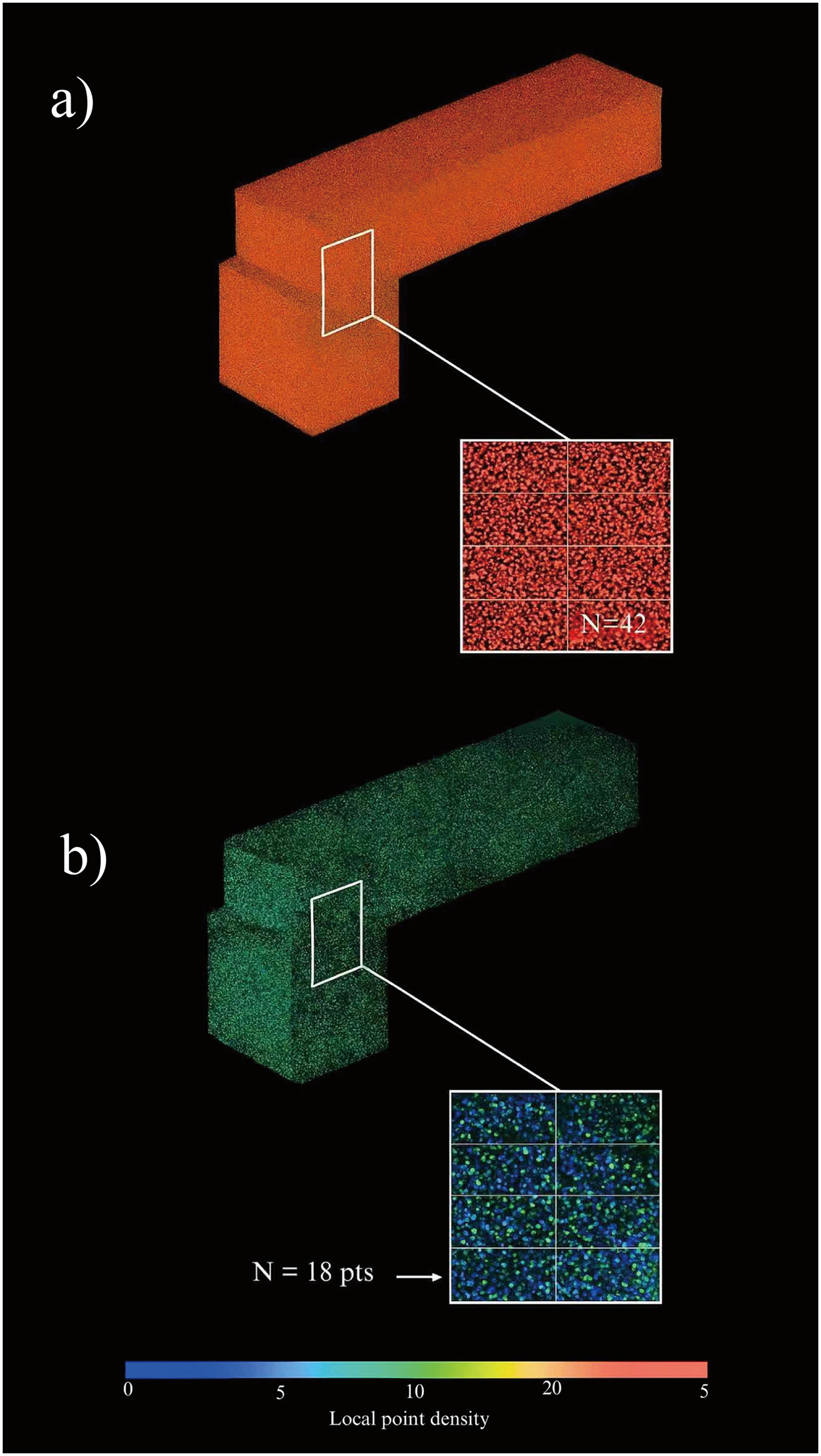
Figure 9 presents the comparative behavior of the local point cloud density in LiDAR- and UAV-based photogrammetry at a prefabricated concrete beam–column joint. Figure 9(a) shows the LiDAR acquisition as a dense carpet of points draped over the joint, whereas Figure 9(b) shows the corresponding photogrammetric reconstruction with visibly sparser sampling and more heterogeneous coverage. In both full-joint views, the same white rectangle was drawn, indicating that the 200 × 200 mm neighborhood was used for quantitative density assessment [26]. Figure 9(c) displays the zoomed patches from these neighborhoods, subdivided into a grid so that individual point spacing becomes apparent, and annotated with representative point counts. The LiDAR patch yielded N = 42 points in a typical grid cell, whereas the photogrammetric patch yielded N = 18 points in the same projected area, indicating that the LiDAR survey recorded approximately 2.3 times of samples [27]. The color scale for local point density shows that the LiDAR data occupy the warmer range of the color map, while the photogrammetry data remain concentrated in cooler blue–green tones, which is consistent with the numerical counts. This study observed similar ratios across multiple cells around the joint, confirming that a higher density is not confined to a single region [28]. These findings suggest that the active laser sampling process produces a more uniform spatial distribution of points, thereby stabilizing the subsequent estimation of surface normals, curvature, and point-to-BIM deviations. The lower, more variable density observed in photogrammetry indicates that image-based reconstruction is more sensitive to illumination, texture, and occlusion, conditions that tend to reduce feature matching and triangulation robustness at edges and recessed surfaces. From a structural quality-control perspective, denser LiDAR sampling is expected to reduce interpolation error and capture subtle deviations at the joint interface that may influence the bearing area, contact pressure, and long-term load transfer between prefabricated elements [29]. This comparison also motivates future work on adaptive fusion strategies, in which LiDAR-derived high-density regions provide geometric constraints for refining photogrammetric reconstructions in zones where image-based point density is insufficient for reliable tolerance verification [30].

(a) LiDAR – full joint point-cloud view and LiDAR zoomed patches showing local point spacing and density statistics, (b) Photogrammetry – full joint point-cloud view and photogrammetry zoomed patches showing local point spacing and density statistics.
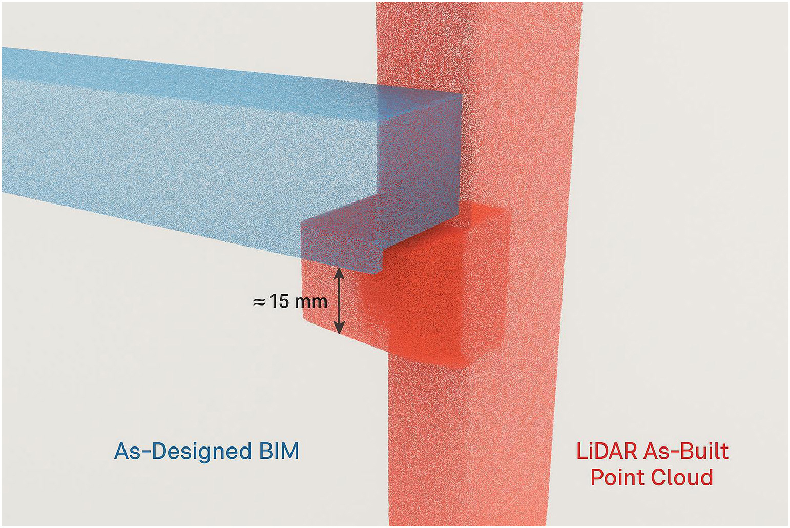
Figure 10 illustrates the behavior of a prefabricated beam–column joint when the as-built configuration deviates from the as-designed BIM reference. The blue element represents the idealized BIM geometry, whereas the red point cloud represents the LiDAR-derived as-built position of the supporting corbel and column. The 15 mm vertical offset indicates the measured downward shift of the bearing surface relative to the design seat. The study observed that this magnitude of misalignment was within the allowable construction tolerance envelope for the mock-up; however, it already reduced the effective bearing length and modified the contact geometry at the interface. The figure shows how the resulting gap changes the engagement of the concrete surfaces and shifts the position at which compressive stresses are transferred from the beam to the column. These findings suggest that even moderate geometric deviations can influence local stress distributions, potential cracking patterns, and long-term serviceability when repeated across multiple joints [31]. The visual overlap between BIM and point cloud also demonstrates that dense LiDAR sampling enables the direct interrogation of geometric discrepancies without intermediate meshing, thereby supporting the reliable extraction of deviation vectors and subsequent structural assessment. This type of representation links the geometric quality control to the mechanical performance by making the load path and bearing conditions explicit. Future studies may extend this approach by coupling measured misalignments with nonlinear contact or time-dependent analyses to examine how repeated tolerance deviations at the system level affect the global stiffness, vibration response, or progressive damage in prefabricated concrete structures [32].
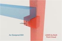
Overlay of as-designed BIM geometry and LiDAR-derived as-built point cloud at a prefabricated beam–column joint showing a measured 15 mm vertical misalignment.
Figure 11 illustrates the behavior of deviation magnitudes at ten critical beam–column and panel–panel connections when ground-truth measurements are compared with LiDAR- and photogrammetry-derived values. The actual deviations at these nodes ranged from approximately 1 mm at C5 to 15 mm at C9, representing realistic erection tolerances in the prefabricated assemblies. The LiDAR values remain very close to the actual values across most connections; the study observed that in 8 of the 10 nodes, the LiDAR estimates differed from ground truth by less than ±1 mm, corresponding to errors on the order of 5–10% of the local deviation [33]. This pattern indicates that the active ranging mechanism and high point density of terrestrial LiDAR preserved the joint geometry with minimal bias, even at nodes with larger offsets such as C4, C6, and C9. The photogrammetry values exhibited larger scatter. At C9, the photogrammetric deviation was approximately 20 mm, compared with the actual 15 mm, and at C8, the method overstated the deviation by more than 25%, revealing sensitivity to texture, shadowing, and occlusion in heavily reinforced joints. Some nodes, such as C2 and C5, showed close agreement with the ground truth, suggesting that favorable imaging geometry and surface contrast can yield accurate reconstructions, but the lack of consistency limits the confidence in tolerance control. These results suggest that LiDAR provides a more reliable basis for BIM-integrated QA/QC of prefabricated joints, whereas photogrammetry is better suited for supplementary assessment or hybrid schemes that use LiDAR anchors for stabilisation-based measurements [34].
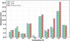
Node-level deviation comparison among ground-truth measurements, LiDAR, and UAV-based photogrammetry for ten prefabricated concrete connections.
Standard aggregate error metrics were additionally reported to complement the node-wise comparisons shown in Figure 10. The Mean Absolute Error (MAE) and Root Mean Square Error (RMSE) were computed across C1–C10 by taking the absolute and squared differences, respectively, between the technology-derived deviations and the total-station ground truth at each node and then averaging across nodes (Table 5). Lower MAE and RMSE values were obtained for LiDAR (MAE = 1.21 mm; RMSE = 2.02 mm) than for photogrammetry (MAE = 1.47 mm; RMSE = 2.15 mm), with both metrics dominated by the largest outliers at C8 and C9.
Error metrics (MAE and RMSE) for node-level deviation estimates against total-station ground truth.
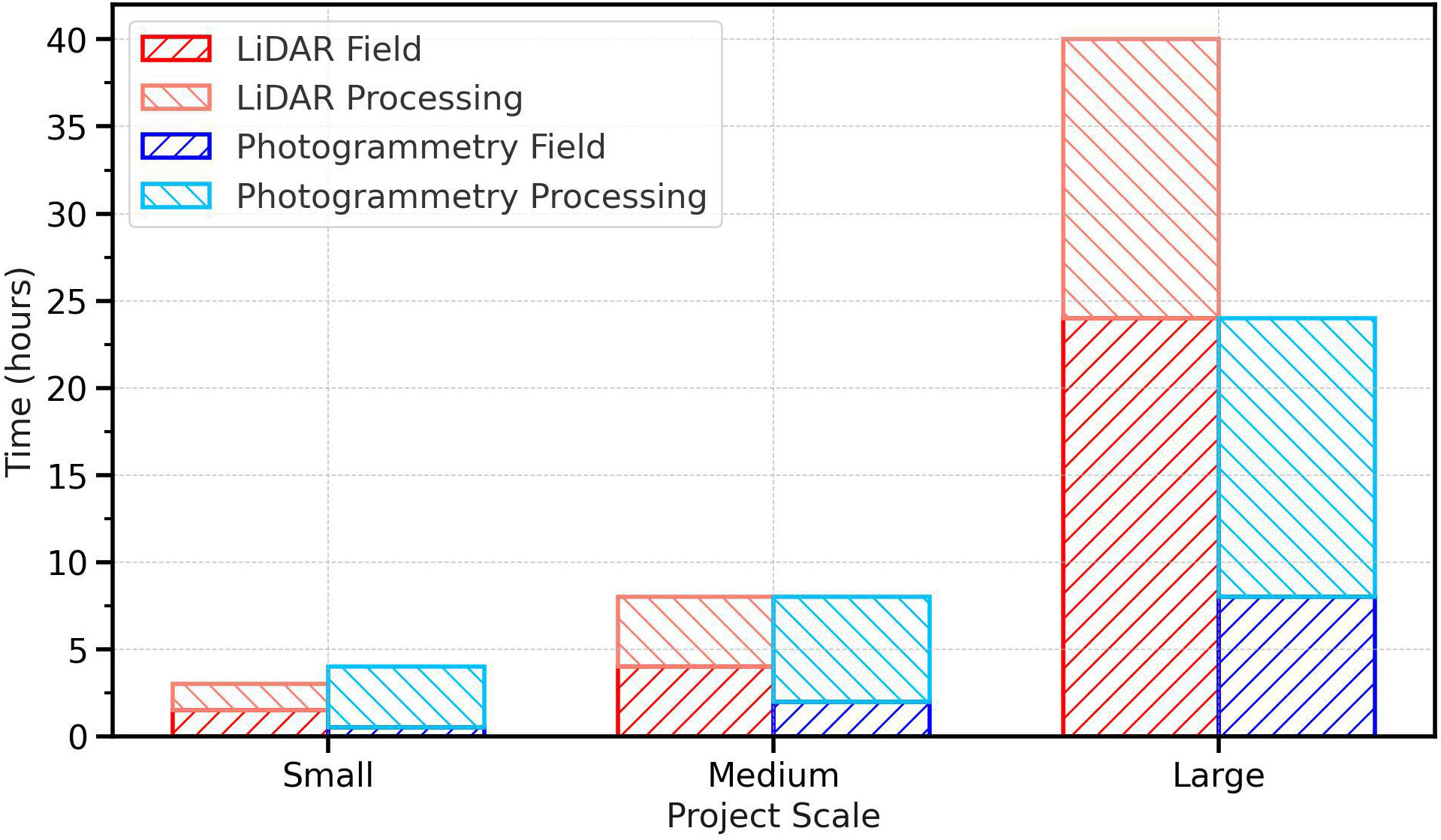
Figure 12 presents the trend in the total time demand for LiDAR- and UAV-based photogrammetry workflows as the project scale increased from small to large prefabricated concrete applications. For small projects, the data indicated that LiDAR required approximately 1.5 hours in the field and 1.5 hours of processing, while photogrammetry used only 0.5 hours in the field but approximately 3.5 hours of processing; therefore, both methods were completed within a normal working day but with different labor–computation balances. For medium projects, each technique accumulated approximately 8 h in total. LiDAR time was split evenly between field acquisition and processing, whereas photogrammetry retained a field advantage but incurred approximately 6 h of reconstruction and registration [35]. For large projects, LiDAR consumed 24 h of on-site scanning and 16 h of processing, for a total of 40 h, whereas photogrammetry limited the field effort to 8 h while still requiring 16 h of processing for dense reconstruction and BIM integration. The results show that computational stages account for most of the photogrammetry time demand, while LiDAR time is dominated by on-site data capture. These results suggest that field logistics and labor constraints favor photogrammetry on expansive or difficult-access sites. In contrast, applications that prioritize predictable processing times and tight dimensional control may prefer LiDAR, especially when scanning resources and scheduling can accommodate longer field components [36].
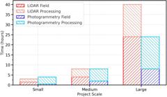
LiDAR and UAV-based photogrammetry field and processing time as a function of project scale.
Higher up-front or rental costs are typically associated with terrestrial scanning equipment, whereas lower hardware entry costs are typically associated with UAV imaging systems, although specialized flight compliance and pilot training costs are often incurred. Labor costs were primarily determined by field hours for LiDAR and office-based reconstruction and registration hours for photogrammetry, as reflected in the field–processing partitioning shown in Figure 11. Computational costs were primarily concentrated in dense reconstruction and registration for photogrammetry, where workstation or cloud resources and extended processing runtimes were required, whereas LiDAR processing demands were generally shorter but coupled to longer on-site acquisition. Because unit prices, wage rates, and software licensing vary by region and procurement model, currency-valued estimates were not provided [37]. Instead, a structured qualitative comparison of cost drivers was provided to address the reviewer’s request, as summarized in Table 6 and referenced in Figure 11.
Indicative cost drivers aligned with field and processing time components reported in Figure 11.
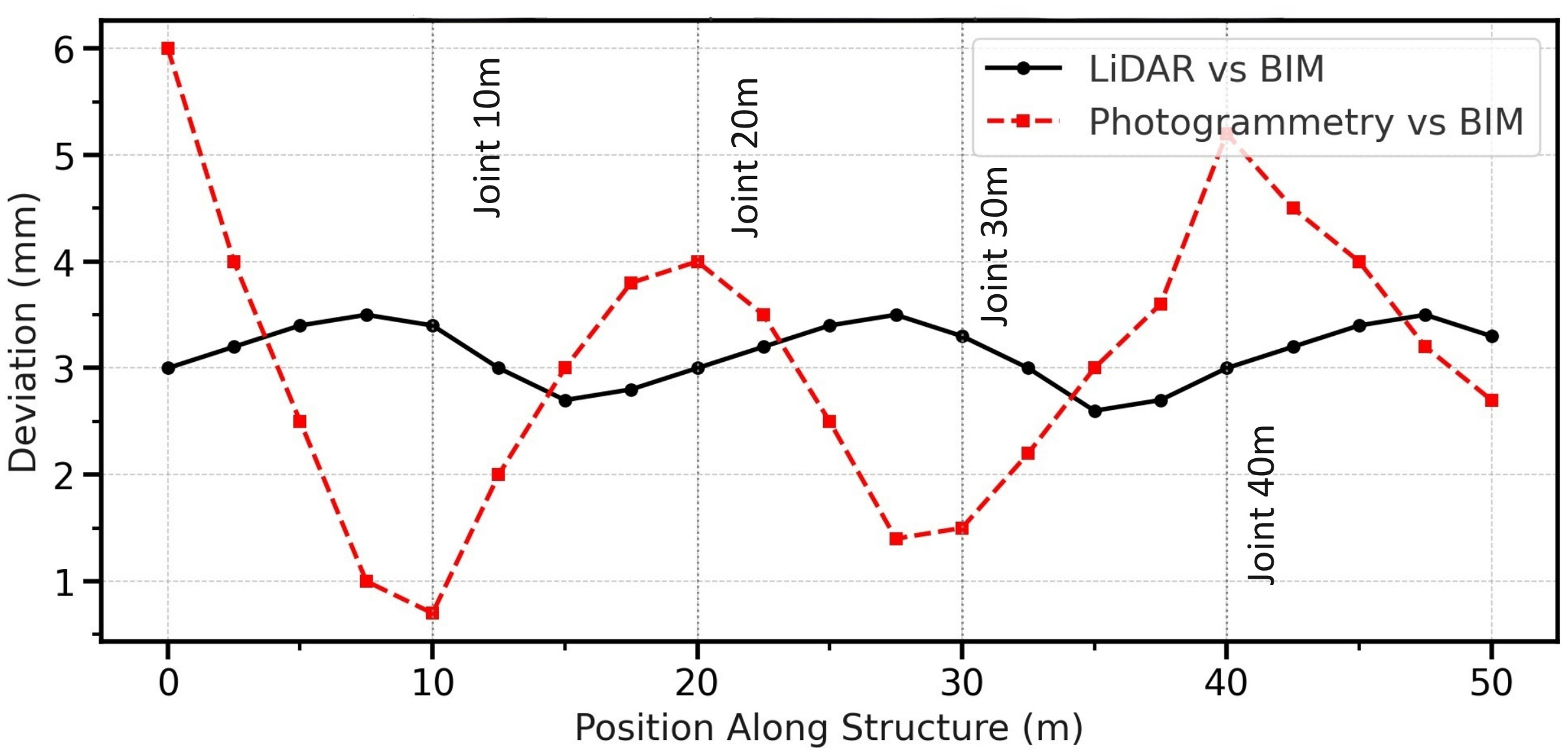
Figure 13 illustrates the behavior of the deviation magnitudes obtained from LiDAR- and UAV-based photogrammetric point clouds when they were aligned with the BIM model along the length of the prefabricated concrete assembly. The LiDAR curve lies between about 2.7 and 3.6 mm and varies smoothly, indicating that the terrestrial scan produced a nearly uniform systematic offset that is consistent with typical registration and instrument calibration uncertainty. The data indicated that no abrupt deviation spikes occurred at the major joints, suggesting that the LiDAR workflow captured the global geometry and local connections without a significant loss of accuracy at transitions [38]. In contrast, the photogrammetry curve exhibited pronounced peaks of approximately 6 mm at 0 m and 5.2 mm at 40 m, with local minima of approximately 0.7–1.0 mm near 10 m, revealing a more erratic deviation pattern. These oscillations are characteristic of sensitivity to texture quality, perspective geometry, and shadowing at different locations along the structure, particularly near joints, where occlusions and low-contrast surfaces reduce the robustness of feature matching. The comparison shows that LiDAR behaves as a stable, bias-dominated measurement system, whereas photogrammetry behaves as a noise-dominated system whose accuracy depends strongly on local imaging conditions [39]. These results suggest that for tolerance control of prefabricated assemblies along their full length, LiDAR provides more reliable bounds on dimensional compliance, whereas photogrammetry may require careful flight planning, surface preparation, or hybrid correction using LiDAR benchmarks to achieve comparable verification performance. [40]. This demonstrates that LiDAR provides a much more predictable and consistent deviation profile, particularly across complex structural segments. Although photogrammetry may suffice for general surveying, its accuracy instability—up to 140% higher at joints—makes it less reliable for precision-critical prefabrication QA/QC. Thus, LiDAR is the preferred method for applications involving strict dimensional compliance.
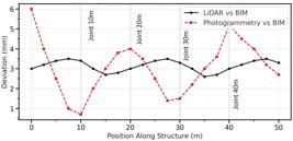
Deviation of LiDAR- and UAV-based photogrammetry–derived as-built geometry from the BIM reference along the prefabricated concrete structure.
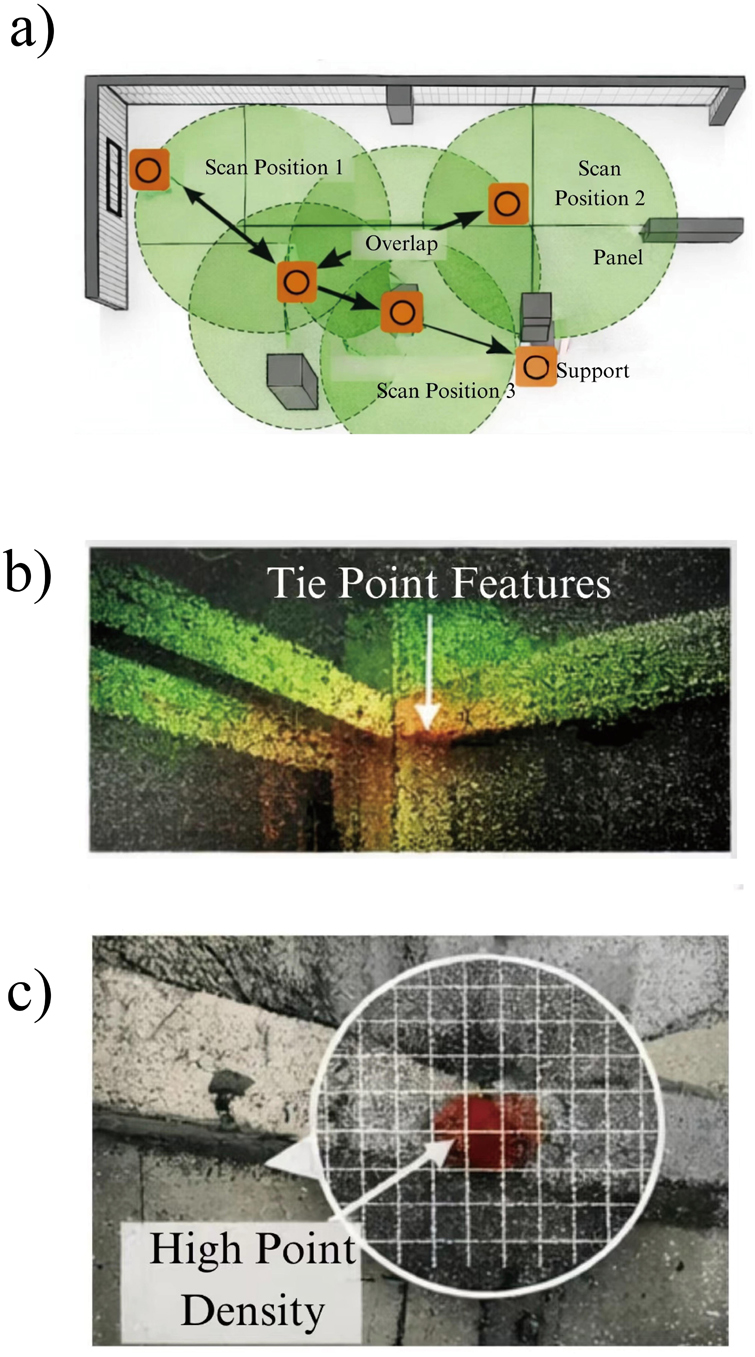
Figure 14 illustrates a practical indoor panoramic terrestrial LiDAR strategy in which occlusion is controlled through planned redundancy, and registration is stabilized through repeatable tie information. Figure 14(a) depicts multiple scan positions distributed around a constrained interior footprint, with overlapping fields of view intentionally intersecting across the central zone and around an obstructing panel and support element. The overlap regions are positioned such that shadow zones behind obstacles intersect from at least one alternative viewpoint, and scan-to-scan continuity is maintained along circulation paths that remain accessible under indoor congestion [41]. Figure 14(b) highlights a high-contrast geometric corner region in the point cloud where repeatable tie-point features are present, and such features are preferred because stable curvature and edge geometry remain identifiable across changing incidence angles and partial occlusions. During the experimental workflow, registration residuals were reduced when bracketing stations were used on both sides of the dominant obstacles and when tie geometry was reused across adjacent scans. Convergence during iterative refinement improved when overlap was preserved at critical joint proximities [42]. Figure 14(c) depicts a density verification concept in which a joint-centered window is inspected using a grid overlay, and a high-density patch is isolated for acceptance prior to deviation computation against the BIM surface. In the completed study, density sufficiency was confirmed within joint windows before signed point-to-surface distances were interpreted. Unstable deviation artifacts were avoided by flagging sparse or anisotropic sampling and mitigating them with added stations or height adjustments. These coupled mechanisms indicate that the interactions among obstacle-driven visibility, overlap-controlled registration observability, and joint-scale sampling adequacy govern the quality of panoramic indoor scanning. Reliable tolerance verification is therefore enabled when station geometry is selected to preserve loop consistency, tie features are maintained across scans, and density checks are enforced at the interfaces that control the prefabricated assembly performance [43].
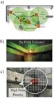
(a) indoor scan-station placement and overlap planning around obstacles; (b) geometric tie-point feature region for cross-station registration; (c) joint-centred point-density window and grid-based coverage check.
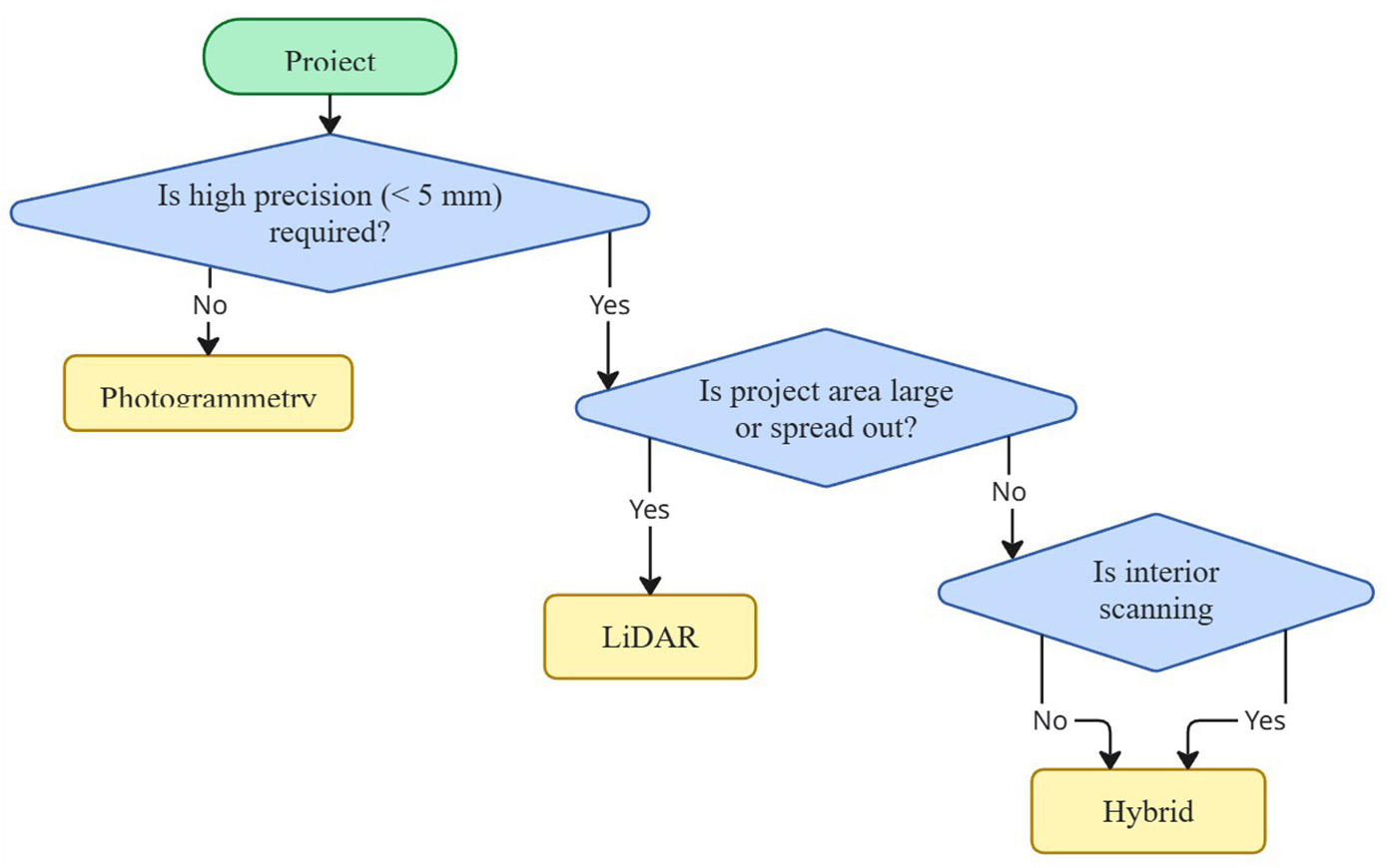
Figure 15 illustrates the behavior of a decision-making workflow that links measurable project requirements to an appropriate sensing strategy for as-built BIM verification in prefabricated concrete construction. The tree begins with the precision requirement; when dimensional tolerances looser than 5 mm are acceptable, the path terminates at photogrammetry, reflecting that the experiments observed deviations of 2.5–6.7 mm yet fast and economical field deployment. When higher precision is required, the logic tends toward LiDAR or hybrid configurations, consistent with the finding that LiDAR maintains joint-level deviations of 1.8–3.2 mm with dense, uniform point clouds. The second branch addresses the project scale [44]. For large or spatially dispersed areas, the diagram routes directly to LiDAR, indicating that the study achieved stable accuracy across the full structural length and robust performance under variable environmental conditions, which is critical when cumulative geometric errors can propagate across many modules [45]. The third branch addresses interior scanning; when interior coverage is required, the workflow directs users to a hybrid solution that uses LiDAR for complex or occluded interior joints and photogrammetry for exterior envelopes, exploiting the latter’s rapid aerial coverage and rich texture. Even when interior work is not mandated, the figure favors a hybrid strategy, suggesting that concentrated LiDAR use at critical interfaces, combined with photogrammetric context, can optimize measurement fidelity, cost, and logistical effort [46]. These decision rules translate empirical performance metrics into a practical selection tool that can guide the design of QA/QC workflows and inform future refinement of hybrid sensing schemes.
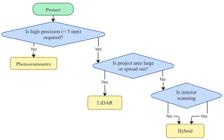
Decision framework for selecting LiDAR, photogrammetry, or hybrid reality capture workflows for BIM-based verification in prefabricated concrete projects.
Although the decision framework illustrated in the figure was derived directly from the measured accuracy, completeness, and effort characteristics observed for terrestrial LiDAR and UAV-based photogrammetry in the BIM-referenced testbed, formal validation was not performed within the current experimental program. The framework should therefore be interpreted as an evidence-informed conceptual guide intended to translate the reported performance boundaries into actionable sensing-selection logic, rather than as a universally validated decision rule applicable to all prefabricated concrete projects. Generalizability is expected to depend on project-specific factors such as joint geometry, surface texture, occlusion severity, site access constraints, and environmental conditions, which influence reconstruction stability and registration uncertainty. Validation was identified as the next step [47]. It should be applied to independent prefabricated projects where the modality recommended by the framework is evaluated against ground-referenced joint deviations, longitudinal deviation stability, point-density sufficiency at critical interfaces, and quantified uncertainty bounds under varying field conditions.
4. CONCLUSIONS
Terrestrial LiDAR scanning and UAV-based photogrammetry were comparatively evaluated for the BIM-referenced verification of prefabricated concrete joints using a full-scale mock-up. Higher reliability was indicated for LiDAR, as over 85% of surface points were contained within ±1 mm of the BIM geometry and joint mean deviations were maintained within 1.8–3.2 mm, while photogrammetry produced larger and more variable joint mean deviations of 2.5–6.7 mm with local peaks approaching +5 mm. Close agreement with the total-station ground truth was generally maintained by LiDAR at most nodes, whereas larger scatter was exhibited by photogrammetry at high-deviation joints. Denser joint sampling was also provided by LiDAR, with approximately 2.3× higher local point counts in the 200 × 200 mm assessment window, and smoother deviation behavior was maintained along the 50 m longitudinal profile, while photogrammetry deviations oscillated with pronounced peaks.
Practical considerations were clarified by the time–effort results, as LiDAR demand was dominated by field acquisition at larger scales, whereas photogrammetry demand was dominated by reconstruction and registration times. Therefore, a decision framework was supported in which LiDAR was preferred when strict dimensional compliance and stable error bounds were required; photogrammetry was favored for rapid large-area coverage under looser tolerances, and hybrid workflows were justified when critical interfaces required millimeter-level verification.
Broader implications for prefabrication QA/QC are indicated. Stronger industry adoption could be enabled by incorporating standardized BIM-referenced deviation reporting, node-level benchmarking, and density checks into inspection specifications and digital handover records, thereby improving traceability and consistency in tolerance-acceptance decisions.
5. BIBLIOGRAPHY
-
[1] XIA, Z., SHU, J., DING, W., et al, “Complete-coverage path planning for surface inspection of cable-stayed bridge tower based on building information models and climbing robots”, Computer-Aided Civil and Infrastructure Engineering, v. 40, n. 25, pp. 4149–4171, 2025. doi: https://doi.org/10.1111/mice.13469.
» https://doi.org/10.1111/mice.13469 -
[2] VALES-BRAVO, J.J., MÉNDEZ-CABALLERO, E.M., PRIETO-MOLINA, R., et al, “LiDAR-photogrammetry coverage, bathymetry and infrastructures survey to support flood risk analysis in the Genil River sub-basin”, Revista De Teledeteccion, n. 63, pp. 79–97, 2024. doi: https://doi.org/10.4995/raet.2024.20481.
» https://doi.org/10.4995/raet.2024.20481 -
[3] BOLKAS, D., GUTHRIE, K., DURRUTYA, L., “sUAS LiDAR and photogrammetry evaluation in various surfaces for surveying and mapping”, Journal of Surveying Engineering, v. 150, n. 1, pp. 04023021, 2024. doi: https://doi.org/10.1061/JSUED2.SUENG-1410.
» https://doi.org/10.1061/JSUED2.SUENG-1410 -
[4] CROCE, V., CAROTI, G., PIEMONTE, A., et al, “H-BIM and artificial intelligence: classification of architectural heritage for semi-automatic scan-to-BIM reconstruction”, Sensors, v. 23, n. 5, pp. 2497, 2023. doi: https://doi.org/10.3390/s23052497. PubMed PMID: 36904701.
» https://doi.org/10.3390/s23052497 -
[5] WEI, X., XIE, S., LUO, A., et al, “Performance improvement of ecologically friendly ultra-high performance concrete with waste tire recycled steel fiber”, Construction & Building Materials, v. 495, pp. 143607, 2025. doi: https://doi.org/10.1016/j.conbuildmat.2025.143607.
» https://doi.org/10.1016/j.conbuildmat.2025.143607 -
[6] ESTOLANO, V., FUCALE, S., VIEIRA FILHO, J.O., et al, “Assessment of static and dynamic modulus of elasticity in concrete made with recycled aggregate from concrete precast rejects”, Matéria, v. 23, e11974, 2018. doi: https://doi.org/10.1590/s1517-707620170001.0310.
» https://doi.org/10.1590/s1517-707620170001.0310 -
[7] EHRENBRING, H.Z., ORTOLAN, V., BOLINA, F., et al, “Residual strength evaluation of hollow core slabs of reinforced concrete of an industrial building after fire”, Matéria, v. 22, e11874, 2023. doi: https://doi.org/10.1590/s1517-707620170003.0208.
» https://doi.org/10.1590/s1517-707620170003.0208 -
[8] GUO, M., LIANG, X., ZHAO, Y., et al, “Seismic deformation analysis of precast concrete pipe hybrid based on 3D LiDAR and unmanned aerial vehicle photogrammetry”, Sensors and Materials, v. 36, n. 7, pp. 3025–3045, 2024. doi: https://doi.org/10.18494/SAM5076.
» https://doi.org/10.18494/SAM5076 -
[9] WANG, X., LIU, H., MENG, X., et al, “GPR-FWI-Py: open-source python software for multi-scale regularized full waveform inversion in ground penetrating radar using random excitation sources”, Computers & Geosciences, v. 197, pp. 105870, 2025. doi: https://doi.org/10.1016/j.cageo.2025.105870.
» https://doi.org/10.1016/j.cageo.2025.105870 -
[10] DARVASI, Y., LAUGOMER, B., SHICHT, I., et al, “Drone-borne LiDAR and photogrammetry together with historical data for studying a paleo-landslide reactivated by road-cutting and barrier construction outside Jerusalem”, Geotechnics, v. 4, n. 3, pp. 786–806, 2024. doi: https://doi.org/10.3390/geotechnics4030041.
» https://doi.org/10.3390/geotechnics4030041 -
[11] SUN, T., GUO, R., CHEN, G., et al, “RID-LIO: robust and accurate intensity-assisted LiDAR-based SLAM for degenerated environments”, Measurement Science & Technology, v. 36, n. 3, pp. 036313, 2025. doi: https://doi.org/10.1088/1361-6501/adb769.
» https://doi.org/10.1088/1361-6501/adb769 -
[12] ALCANTARA, M.A.D.M., NUNES, S.C.B., RIO, J.F.M.E., et al, “Rheology and mechanical aspects of a self-compacting soil-cement in the fresh state”, Matéria, v. 22, pp. e11876, 2017. https://doi.org/10.1590/S1517-707620170003.0210.
» https://doi.org/10.1590/S1517-707620170003.0210 -
[13] PALANISAMY, G., KUMARASAMY, V., “Rehabilitation of damaged RC exterior beam-column joint using various configurations of CFRP laminates subjected to cyclic excitations”, Matéria, v. 28, e20230110, 2023. doi: https://doi.org/10.1590/1517-7076-RMAT-2023-0110.
» https://doi.org/10.1590/1517-7076-RMAT-2023-0110 -
[14] ZHAN, X., ZHANG, X., WANG, X., et al, “Comparative analysis of surface deformation monitoring in a mining area based on UAV-lidar and UAV photogrammetry”, The Photogrammetric Record, v. 39, n. 186, pp. 373–391, 2024. doi: https://doi.org/10.1111/phor.12490.
» https://doi.org/10.1111/phor.12490 -
[15] JAMŠEK RUPNIK, P., ATANACKOV, J., ZAJC, M., et al, “revealing subtle active tectonic deformation: integrating lidar, photogrammetry, field mapping, and geophysical surveys to assess the late quaternary activity of the sava fault (Southern Alps, Slovenia)”, Remote Sensing, v. 16, n. 9, pp. 1490, 2024. doi: https://doi.org/10.3390/rs16091490.
» https://doi.org/10.3390/rs16091490 -
[16] SUN, G., KONG, G., LIU, H., et al, “Vibration velocity of X-section cast-in-place concrete (XCC) pile–raft foundation model for a ballastless track”, Canadian Geotechnical Journal, v. 54, n. 9, pp. 1340–1345, 2017. doi: https://doi.org/10.1139/cgj-2015-0623.
» https://doi.org/10.1139/cgj-2015-0623 -
[17] SONG, J., ZHOU, X., XU, C., et al, “Training-free automatic instance segmentation of girder bridge point cloud via large model fusion with reverse entity modelling verification”, Automation in Construction, v. 179, pp. 106484, 2025. doi: https://doi.org/10.1016/j.autcon.2025.106484.
» https://doi.org/10.1016/j.autcon.2025.106484 -
[18] COLLINS, F.C., RINGSQUANDL, M., BRAUN, A., et al, “Shape encoding for semantic healing of design models and knowledge transfer to scan-to-BIM”, Proceedings of the Institution of Civil Engineers Smart Infrastructure and Construction, v. 175, n. 4, pp. 160–180, 2022. doi: https://doi.org/10.1680/jsmic.21.00032.
» https://doi.org/10.1680/jsmic.21.00032 -
[19] ZHOU, X., LU, D., ZHAO, J., et al, “Material characteristic length insensitive nonlocal modelling: A computationally efficient scaled nonlocal integral method”, Computers and Geotechnics, v. 188, pp. 107587, 2025. doi: https://doi.org/10.1016/j.compgeo.2025.107587.
» https://doi.org/10.1016/j.compgeo.2025.107587 -
[20] ZHOU, X., LU, D., DU, X., et al, “A 3D non-orthogonal plastic damage model for concrete”, Computer Methods in Applied Mechanics and Engineering, v. 360, pp. 112716, 2020. doi: https://doi.org/10.1016/j.cma.2019.112716.
» https://doi.org/10.1016/j.cma.2019.112716 -
[21] ZHANG, R., WANG, Y., LI, Z., et al, “Online adaptive keypoint extraction for visual odometry across different scenes”, IEEE Robotics and Automation Letters, v. 10, n. 7, pp. 7539–7546, 2025. doi: https://doi.org/10.1109/LRA.2025.3575644.
» https://doi.org/10.1109/LRA.2025.3575644 -
[22] YAO, S., GUAN, R., PENG, Z., et al, “Exploring radar data representations in autonomous driving: a comprehensive review”, IEEE Transactions on Intelligent Transportation Systems, v. 26, n. 6, pp. 7401–7425, 2025. doi: https://doi.org/10.1109/TITS.2025.3554781.
» https://doi.org/10.1109/TITS.2025.3554781 -
[23] YANG, Y., CAO, J., LI, Y., et al, “Effect of electric field on water-film between concrete and formwork: Atomic-scale mechanisms and technology indicators”, Construction & Building Materials, v. 498, pp. 143979, 2025. doi: https://doi.org/10.1016/j.conbuildmat.2025.143979.
» https://doi.org/10.1016/j.conbuildmat.2025.143979 -
[24] YANG, H., LI, S., SHU, J., et al, “Data-driven high-resolution total focus imaging from array ultrasonic time-domain signals of reinforced concrete material”, Construction & Building Materials, v. 492, pp. 143048, 2024 doi: https://doi.org/10.1016/j.conbuildmat.2025.143048.
» https://doi.org/10.1016/j.conbuildmat.2025.143048 -
[25] YANG, G., ZHAO, H., HU, Z., et al, “Prediction of restrained stress for UHPC: Considering relationship between long-term and in-situ creep”, Construction & Building Materials, v. 484, pp. 141722, 2025. doi: https://doi.org/10.1016/j.conbuildmat.2025.141722.
» https://doi.org/10.1016/j.conbuildmat.2025.141722 -
[26] SHEN, Z., HE, Y., DU, X., et al, “YCANet: target detection for complex traffic scenes based on camera-LiDAR fusion”, IEEE Sensors Journal, v. 24, n. 6, pp. 8379–8389, 2024. doi: https://doi.org/10.1109/JSEN.2024.3357826.
» https://doi.org/10.1109/JSEN.2024.3357826 -
[27] NIU, Y., WANG, W., SU, Y., et al, “Plastic damage prediction of concrete under compression based on deep learning”, Acta Mechanica, v. 235, n. 1, pp. 255–266, 2023. doi: https://doi.org/10.1007/s00707-023-03743-8.
» https://doi.org/10.1007/s00707-023-03743-8 -
[28] MA, C., LU, D.C., DU, X.L., et al, “Structural components functionalities and failure mechanism of rectangular underground structures during earthquakes”, Soil Dynamics and Earthquake Engineering, v. 119, pp. 265–280, 2019. doi: https://doi.org/10.1016/j.soildyn.2019.01.017.
» https://doi.org/10.1016/j.soildyn.2019.01.017 -
[29] LUO, Y.X., DONG, Y.L., YANG, F.Q., et al, “Ultraviolet single-camera stereo-digital image correlation for deformation measurement up to 2600 °C”, Experimental Mechanics, v. 64, n. 8, pp. 1343–1355, 2024. doi: https://doi.org/10.1007/s11340-024-01087-5.
» https://doi.org/10.1007/s11340-024-01087-5 -
[30] LU, D., MENG, F., ZHOU, X., et al, “A dynamic elastoplastic model of concrete based on a modeling method with environmental factors as constitutive variables”, Journal of Engineering Mechanics, v. 149, n. 12, pp. 04023102, 2023. doi: https://doi.org/10.1061/JENMDT.EMENG-7206.
» https://doi.org/10.1061/JENMDT.EMENG-7206 -
[31] SUN, L., WANG, X., ZHANG, C., “Three-dimensional high fidelity mesoscale rapid modelling algorithm for concrete”, Structures, v. 70, pp. 107561, 2024. doi: https://doi.org/10.1016/j.istruc.2024.107561.
» https://doi.org/10.1016/j.istruc.2024.107561 -
[32] BASKAR, K., GANESAN, A., BASKAR, K., “Dual waste valorization in concrete: a performance-based study on waste foundry sand and bottom ash materials”, Matéria, v. 30, e20250307, 2025. doi: https://doi.org/10.1590/1517-7076-rmat-2025-0307.
» https://doi.org/10.1590/1517-7076-rmat-2025-0307 -
[33] LI, Y., LIU, C., WENG, Z., et al, “Aggregate-level 3D analysis of asphalt pavement deterioration using laser scanning and vision transformer”, Automation in Construction, v. 178, pp. 106380, 2025. doi: https://doi.org/10.1016/j.autcon.2025.106380.
» https://doi.org/10.1016/j.autcon.2025.106380 -
[34] LI, X., WANG, H., HE, Y., et al, “Active thermography nondestructive testing going beyond camera’s resolution limitation: a heterogenous dual-band single-pixel approach”, IEEE Transactions on Instrumentation and Measurement, v. 74, pp. 1–8, 2025. doi: https://doi.org/10.1109/TIM.2025.3545520.
» https://doi.org/10.1109/TIM.2025.3545520 -
[35] LI, R., WANG, Y., SUN, S., et al, “UE-extractor: a grid-to-point ground extraction framework for unstructured environments using adaptive grid projection”, IEEE Robotics and Automation Letters, v. 10, n. 6, pp. 5991–5998, 2025. doi: https://doi.org/10.1109/LRA.2025.3563127.
» https://doi.org/10.1109/LRA.2025.3563127 -
[36] HUANG, H., HUANG, M., ZHANG, W., et al, “Experimental Investigation on rehabilitation of corroded RC columns with BSP and HPFL under combined loadings”, Journal of Structural Engineering, v. 146, n. 8, pp. 04020157, 2020. doi: https://doi.org/10.1061/(ASCE)ST.1943-541X.0002725.
» https://doi.org/10.1061/(ASCE)ST.1943-541X.0002725 -
[37] MURUGAN, A., KALIAPPAN, S.P., SELVARAJAN, A.K., “Mechanical and durability investigation of fiber effect in finer concrete with various admixtures”, Matéria, v. 30, e20250219, 2025. doi: https://doi.org/10.1590/1517-7076-rmat-2025-0219.
» https://doi.org/10.1590/1517-7076-rmat-2025-0219 -
[38] HUANG, H., GUO, M., ZHANG, W., et al, “Seismic behavior of strengthened RC columns under combined loadings”, Journal of Bridge Engineering, v. 27, n. 6, pp. 05022005, 2022. doi: https://doi.org/10.1061/(ASCE)BE.1943-5592.0001871.
» https://doi.org/10.1061/(ASCE)BE.1943-5592.0001871 -
[39] NEVES, P.N., MATOS, V., PEREIRA, C., “Scan-to-BIM protocol for asset inventory: grounding the digital twin for O&M”, International Journal of Building Pathology and Adaptation, 2025. In press. doi: https://doi.org/10.1108/IJBPA-08-2025-0219.
» https://doi.org/10.1108/IJBPA-08-2025-0219 -
[40] GUO, M., HUANG, H., ZHANG, W., et al, “Assessment of RC frame capacity subjected to a loss of corner column”, Journal of Structural Engineering, v. 148, n. 9, pp. 04022122, 2022. doi: https://doi.org/10.1061/(ASCE)ST.1943-541X.0003423.
» https://doi.org/10.1061/(ASCE)ST.1943-541X.0003423 -
[41] CAMPOS, V.R., CARVALHO, R.F., DIAS, C.M.R., “Gesso conformado sob pressão: os efeitos dos parâmetros de conformação sobre as propriedades físicas e mecânicas”, Matéria, v. 28, e20220267, 2022. doi: https://doi.org/10.1590/1517-7076-RMAT-2022-0267.
» https://doi.org/10.1590/1517-7076-RMAT-2022-0267 -
[42] CASTILLO, M.J., MARÍA, V.L.C., MARCONI, C.D., et al, “Effect of welding parameters on welded steel wire mesh”, Matéria, v. 23, e12015, 2018. doi: https://doi.org/10.1590/s1517-707620180002.0352.
» https://doi.org/10.1590/s1517-707620180002.0352 -
[43] FELIX, E.F., CARRAZEDO, R., POSSAN, E., “Experimental analysis of the fatigue life of concrete subject to low cyclic compressive loading”, Matéria, v. 27, e202145017, 2022. doi: https://doi.org/10.1590/1517-7076-rmat-2021-45017.
» https://doi.org/10.1590/1517-7076-rmat-2021-45017 -
[44] GONG, L., GAO, B., SUN, Y., et al, “preciseSLAM: robust, real-time, LiDAR-inertial-ultrasonic tightly-coupled SLAM with ultraprecise positioning for plant factories”, IEEE Transactions on Industrial Informatics, v. 20, n. 6, pp. 8818–8827, 2024. doi: https://doi.org/10.1109/TII.2024.3361092.
» https://doi.org/10.1109/TII.2024.3361092 -
[45] LIU, H., ZHANG, B., YAN, L., et al, “Rebar characterization using dual-polarization GPR”, NDT & E International, v. 154, pp. 103391, 2025. doi: https://doi.org/10.1016/j.ndteint.2025.103391.
» https://doi.org/10.1016/j.ndteint.2025.103391 -
[46] CHEN, J., SUN, L., SONG, Y., et al, “3D surface highlight removal method based on detection mask”, Arabian Journal for Science and Engineering, 2025. In press. doi: https://doi.org/10.1007/s13369-025-10573-4.
» https://doi.org/10.1007/s13369-025-10573-4 -
[47] EISA, A.S., ABOUL-NOUR, L.A., MOHAMAD, A., “Experimental and theoretical investigation on the bond strength between high-strength and lightweight concrete”, Matéria, v. 29, n. 1, e20230312, 2024. doi: https://doi.org/10.1590/1517-7076-rmat-2023-0312.
» https://doi.org/10.1590/1517-7076-rmat-2023-0312
DATA AVAILABILITY
The datasets used in the current study are available from the corresponding author upon reasonable request.