 A framework for load rating existing reinforced concrete bridges
Abstract
Abstract Bridges are essential structures for a country's socioeconomic system; however, in Brazil, most of these structures are over 50 years old. Simultaneously with the aging of these structures, there has been a significant change in the vehicles, mainly in terms of variety, quantity, and load. This work proposes a framework to assess the structural safety of reinforced concrete beam bridges, which includes a two-level method that regulates the amount of information required to assess the structural safety of a bridge. Three bridges located in the state of Minas Gerais, Brazil, were analyzed. The proposed methodology has proven to be effective for the evaluation of bridges, both with original plan reconstruction and core sampling. Furthermore, the proposed framework allows for concluding about the bridge’s safety without conducting load tests.
Keywords:
reinforced concrete bridges; structural evaluation; load rating; existing structures; framework
Resumo
Resumo Pontes são estruturas essenciais para o sistema socioeconômico de um país, porém, no Brasil, a maioria dessas estruturas tem mais de 50 anos de idade. Simultaneamente ao envelhecimento dessas estruturas, houve uma mudança significativa nos veículos, principalmente em termos de variedade, quantidade e carga. Este trabalho propõe uma estrutura para avaliar a segurança estrutural de pontes em viga de concreto armado, que inclui uma estrutura de dois níveis que regula a quantidade de informação necessária para avaliar a segurança estrutural. Foram analisadas três pontes localizadas no estado de Minas Gerais. A metodologia proposta provou ser eficaz para a avaliação de pontes, tanto com a reconstrução do projeto original como com a extração de testemunhos. Além disso, a estrutura proposta permite concluir sobre a segurança da ponte sem a necessidade de recorrer a provas de carga.
Palavras-chave:
pontes de concreto armado; avaliação estrutural; capacidade de carga; estruturas existentes; fluxograma
1. INTRODUCTION
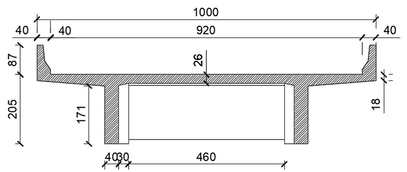
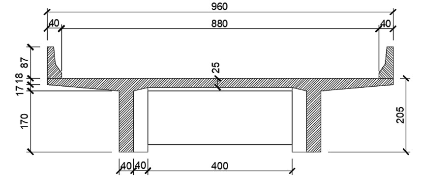
Bridges are essential elements for the socio-economic system of a country, especially in a country where roads are the predominant means of transportation, such as Brazil [1]. A study by Mendes [2] shows that most of the bridges on the Brazilian federal highway network are more than 50 years old and made of reinforced concrete, some of which lack information, such as the construction year, design type (road class), and structure type. Guimarães et al. [3] explain that the absence of information occurs due to the lack of proper cataloging and records when these structures are replaced, restored, or rehabilitated. One alternative for obtaining information on the design period, provided they have maintained or undergone minor modifications to their original characteristics, is the Bridge Inspection Manual [4], which indicates the typical cross-sections of various periods.
Parallel to the aging of these structures (many with noticeable signs of deterioration and with no knowledge of the degree to which the structure is compromised), the characteristics of the vehicles that travel on Brazilian highways have changed significantly in recent decades, mainly by increasing the variety, quantity, and load capacity [5]. Therefore, existing structures, especially older ones with a higher degree of deterioration, need a complete analysis of the structure's behavior. With the lack of information for this analysis, the Brazilian standard NBR 7187 [6] recommends redesigning the structure based on criteria, recommendations, and standards in effect at the time of its construction and assessing the structure against current load conditions and standards.
This work proposes a framework for the structural safety evaluation of in-service reinforced concrete bridges. Two main approaches are proposed, relying either on original design plan reconstruction or coring the structure to determine the concrete properties. Also, one approach relies only on visual inspection for condition state assessment, while the other uses non-destructive techniques (NDT) to complement the visual inspection.
2. BRIDGE LOAD RATING
One of the simplest methods for load rating existing bridges is the calculation of the Rating Factor (RF), a safety factor proposed by AASHTO [7] and adopted by several authors [8]–[11]. This safety metric consists of the ratio between the resistance of the analyzed section to live loads and the load effects due to the live load of the analyzed vehicle on the same section. The RF is calculated by Equation 1:
where is the load-bearing capacity of the section; is a reduction factor for the load-bearing capacity based on the condition state of the bridge; are the values of the load effects due to the permanent loads; are the values of the load effects due to the live loads; and are factors used for load combination applied to the permanent and live loads, respectively; and is the dynamic amplification factor.
If the RF is a value greater than 1.0, it indicates that the structure can be considered safe for the traffic of the analyzed vehicle; on the other hand, if the value is less than 1.0, it means that the structure cannot be considered safe, and it may be necessary to carry out more complex studies. Several countries have proposed a level structure assessment procedure that increases the requirements for assessment as the structure fails the simplified analysis [7], [12]–[15]. Ultimately, when the safety of the structure cannot be verified at any level, a load test must be conducted to evaluate the structure's behavior.
Load testing is one of the most efficient tests for assessing the safety of an existing structure; however, it is not always feasible due to the high cost, time, test requirements, and the need for interruption or redirection of traffic and safety [16]. Load tests can be static or dynamic and are used to assess the performance of structures and verify that they will work within the Service Limit State (SLS), as established by current Brazilian regulations. In European and North American countries, it is common to carry out these tests on bridges before they are opened to traffic; however, in Brazil, load tests are more restricted to situations in which the bridge safety has to be assessed or we want to obtain more information about the behavior of structures that do not have structural design plans or that have been reinforced [17].
3. FRAMEWORK
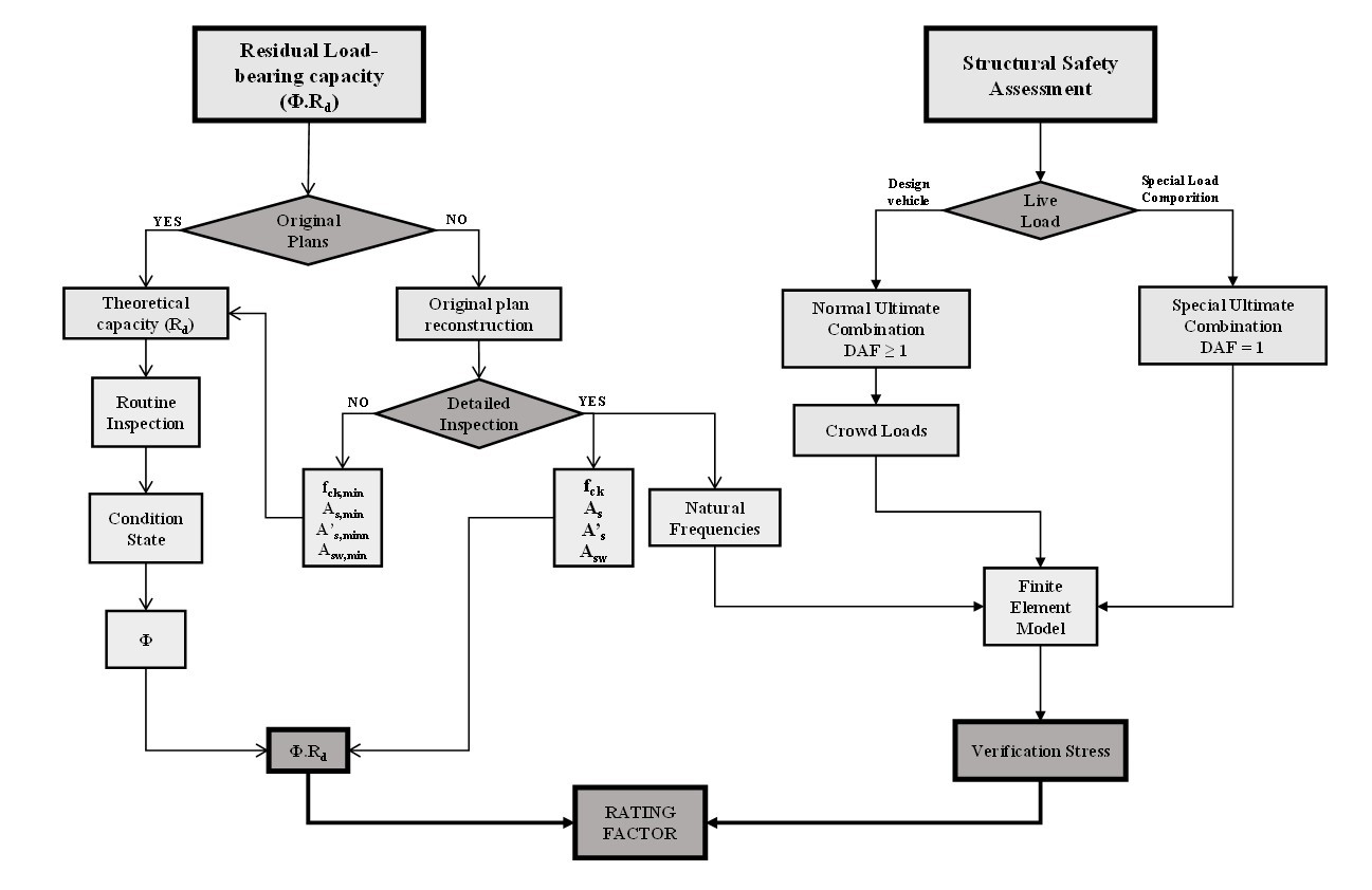
The framework proposed for calculating the RF is shown in Figure 1. The process includes two main tasks, the residual load-bearing capacity estimation and the safety assessment based on the verification load effects.

The load-bearing capacity estimation mostly depends on the availability of the original construction plans. If this information is available, the original design parameters should be used to estimate the theoretical load-bearing capacity. On the other hand, if such information is missing, the original plans must be reconstructed based on the standards in force when the structure was first designed.
However, the RF calculation depends on the residual load-bearing capacity; thus, the structural degradation must be assessed through a routine inspection. Additionally, more reliable information may be gathered in a detailed inspection through non-destructive testing (NDT) or core extraction.
The verification of structural safety is conducted for a specific live load composition, which will determine the traffic conditions and, consequently, the load combination. The verification load effects are estimated through a finite element model, and the RF is calculated according to Equation 1.
3.1. Load-bearing capacity
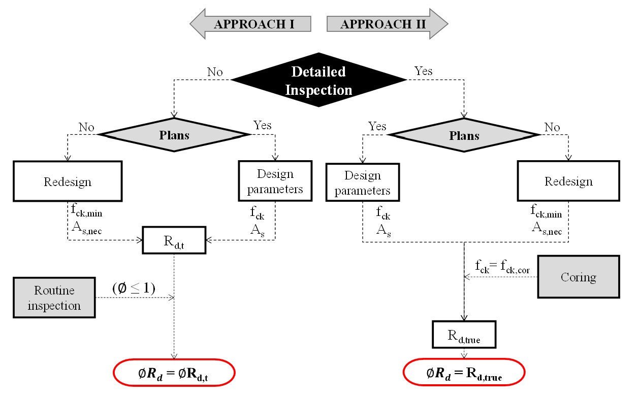
The residual load-bearing capacity () is calculated by estimating the bridge's nominal load-bearing capacity and applying an additional factor to account for the structure deterioration. The component can be estimated using two approaches (Figure 2). Approach I does not rely on a Special Inspection as it does not include experimental tests. As a result, Approach I relies on original design plans or historical criteria for bridge design as tools for estimating the theoretical load-bearing capacity of each bridge (). Furthermore, the capacity deterioration factor () is based on the bridge's condition state determined through a Routine Inspection.
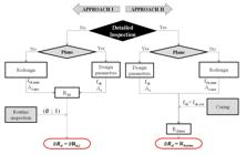
On the other hand, Approach II includes a Special Inspection and estimates the residual resistance capacity of the element based on results obtained through experimental tests. The design parameters are obtained either by the original design parameters or by redesigning the bridge. The “real” concrete compressive strength is obtained by coring the structure, and this information is used only for estimating the true load-bearing capacity. Both approaches calculate the residual strength capacity of the structure using the current standards.
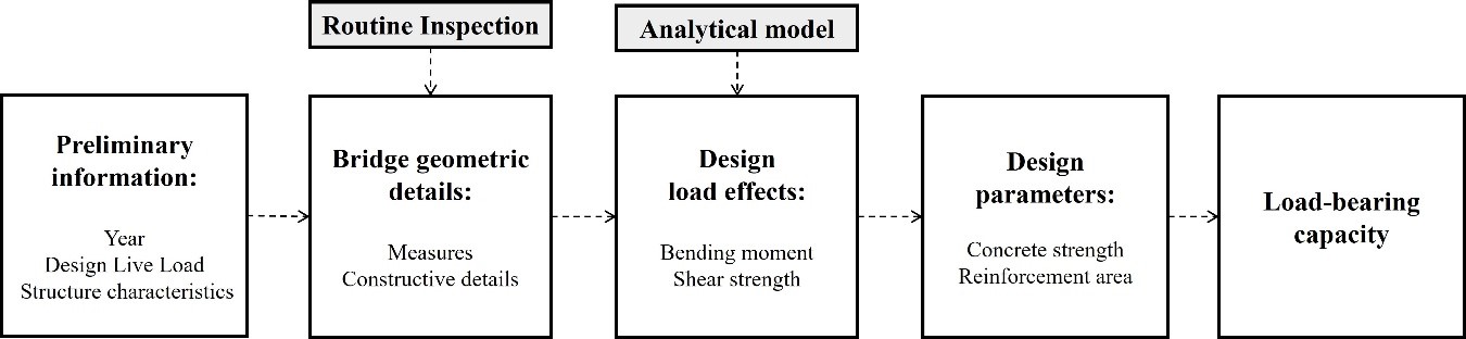
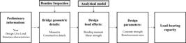
Due to insufficient information about existing structures, most bridges must be redesigned to estimate the design parameters, i.e., the concrete compressive strength and reinforcement area (Figure 3). First, preliminary information is gathered, such as year of construction, design class, and type of structure. Then, based on a routine inspection, information on the construction details and dimensions of the structure is collected. After surveying the geometry of the bridge and its respective design class, the analytical model of the structure is created and used to estimate the design load effects. When the original design parameters are unknown, it is necessary to redesign the structure and then calculate the section resistance. Firstly, the concrete strength is assessed by checking the compressed concrete struts. Then, the minimum reinforcement area is estimated according to the standards in effect at the time of the bridge construction. In this case, the reinforcement area is based on the design load effects and cross-sectional measures. The load-bearing capacity is later calculated based on the assessed design parameters.
3.2. Original plans redesign
The structural safety assessment of existing structures often relies on design information, which is frequently unavailable. Briones [18] highlights the challenge due to this lack of information and suggests a methodology for assessing bridges without design documentation. Although there are some studies on the structural safety evaluation of reinforced concrete bridges without design plans, this area remains underexplored, with a clear gap between the strategies adopted in other countries and those used in Brazil.
NBR 7187 [6] recommends that when the original executive designs are unavailable or there is insufficient construction detail to support a complete analysis of the structure's behavior, it is necessary to reconstruct the design based on the criteria, recommendations, and standards in effect at the time of construction, followed by a verification of the current load conditions and compliance with current standards. The design reconstruction aims to estimate the concrete's compressive strength used in the design and the minimum reinforcement. These estimates allow for calculating the minimum strength of each section of the structural element under analysis to verify structural safety.
3.2.1. Design criteria evolution
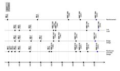
Changes in the design characteristics of reinforced concrete bridges (such as alterations in loadings and cross-sections) required revisions in Brazilian standards for the design and execution of these structures [3]. Different evaluation methods used by researchers highlighted the need for standardization. Thus, the Technical Standards Brazilian Association (ABNT) was founded in 1940 as the organization responsible for technical standardization in Brazil. Figure 4 shows the timeline of the evolution of standards related to reinforced concrete bridge design.
3.2.1.1. Reinforced Concrete Design
In 1940, based on the Allowable Stress Method (MTA), the first standard for the calculation and execution of reinforced concrete structures was introduced, the NB 1 [19]. In this standard, the allowable compressive stresses of concrete were calculated based on the average rupture stress of concrete in compression (which corresponds to the current standard's average compressive strength of concrete at 28 days of age, fcm,28). Additionally, there were no load combination factors applied to actions until NB 1 [20], where all actions were considered to act simultaneously on the structure at their nominal values.
While NB 1 [20] was valid, structural elements were designed in two ways: they were either calculated in Stage III based on the rupture load using safety factors for the actions, or in Stage II based on the allowable stresses. Moreover, the allowable compressive stresses of concrete were then calculated based on the minimum rupture stress of concrete in compression.
Later, on NB 1 [21], also known as NBR 6118 [22], the design of reinforced concrete structures changed to the Limit State Method (LSM). Unlike the MTA, where all actions have the same variability, the LSM accounts for the non-negligible probability of simultaneous occurrence of actions through combinations of actions. Currently, ABNT NBR 8681 [23] deals with actions and safety in structures.
The acronym fck referring to the characteristic compressive strength of concrete, also emerged in NB 1 [21]. According to Araújo [24], it is generally accepted that the probability density function of compressive strengths of concrete follows the normal Gaussian curve, with the term fck representing the value that has a 5% probability of being lower.
On NBR 6118 [25], the standard focused solely on the design of concrete structures, leaving the execution part to NBR 14931 [26]. Design criteria aimed at durability were introduced in NBR 6118 [25], such as the quality of the concrete cover for reinforcement, which correlates water/cement ratios by mass, concrete class, and minimum cover with the Environmental Aggressiveness Classes (CAA). In addition to durability-related criteria, fatigue verification of concrete in compression and tension began to be considered from NBR 6118 [25] onward.
Finally, high-strength concretes (C55 to C90), as classified by NBR 8953 [27] and also known as high-performance concretes, began to be addressed only with the publication of NBR 6118 [28].
3.2.1.2. Reinforcement for RC structures
The concrete design standards (NB 1 and NBR 6118) specified the categories of steel allowed but more specific characteristics, including fatigue verification criteria, are found in the standards related to steels used for reinforcement in reinforced concrete structures (EB 3 [29] and ABNT NBR 7480 [30], [31]).
3.2.1.3. Bridge Design
The first standards for the design of reinforced concrete bridges addressed load definition, including the vertical impact coefficient (φ), the resisting forces, and construction provisions. According to Silva et al. [32], the impact coefficient simplifies the complexity of the dynamic effects of moving loads in structural calculations by using static loads increased by this coefficient.
Up to 1961 [33], the impact coefficient had a constant value. However, NB 2 [34], defined this value as a function of the theoretical span of the loaded element. From 2013 onwards, the impact coefficient has been addressed in the moving loads standard, ABNT NBR 7188 [35], and is composed of three components: the vertical impact coefficient, the lane number coefficient, and the additional impact coefficient.
3.2.1.4. Live Load
The first Brazilian standard for the live loading of road bridges was NB 6 [36], which addressed the classification of bridges and live load composition (design vehicle and crowd loads). Until the publication of NB 6 [37], the design vehicle was composed of a compressor and as many trucks as there were traffic lanes, minus one. Following the publication of NB 6 [37], which is still in effect currently under NBR 7188 [35], the design vehicle was reduced to just one unit.
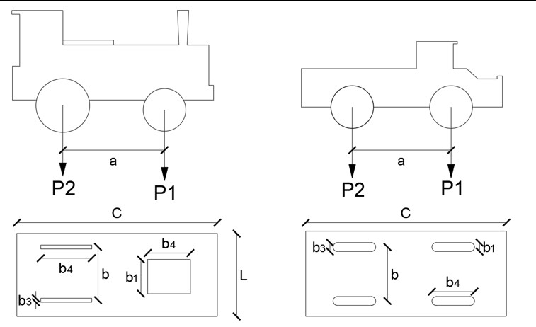
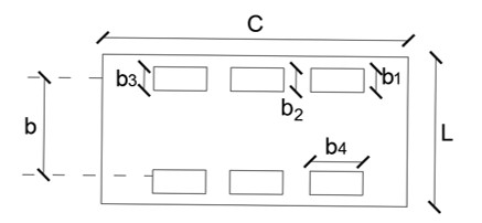
Before the publication of NB 6 [37], the crowd load was uniformly distributed on sidewalks and throughout the roadway, except in the region occupied by the design vehicle. During the period of NB 6, the crowd load was divided into two components: one applied to the longitudinal lane corresponding to the design vehicle, excluding the area occupied by the vehicle, and another applied to the remainder of the roadway and sidewalks. With the publication of NBR 7188 [38], still in effect currently under NBR 7188 [35], the first portion of the crowd load began to be applied over the entire roadway, excluding the region occupied by the vehicle, while the second portion was applied only to the sidewalks. A summary of the live load models over the years is provided in Table 1.
3.3. Bridge condition assessment
Bridge structures are subject to deterioration over time. Therefore, careful attention is necessary to prevent these structures from weakening and becoming vulnerable to the actions of agents (endogenous or exogenous) that could compromise their stability and functionality. Thus, applying inspection methodologies is crucial for bridge management and safety assessment [39], [40]. Some inspection methodologies classify bridges or their components using a condition state rating based on observed damage. A few inspection methodologies are presented in this paper.
In Brazil, there are two main standards for bridge inspection [41], [42]. The DNIT [41] directives provide a qualitative evaluation of the structure, classifying the bridge condition based on the severity of existing problems in its elements (Table 2). The overall condition of the bridge is determined by the rating given to the most deteriorated element. According to Giovanetti and Pinto [43], although this method is straightforward, it is also subjective, as it heavily relies on the inspector's qualifications. Additionally, the bridge's rating can be generalized due to a single instance of damage. The dependability on the inspector’s qualifications, the variability of data from visual inspection, and the use of new technologies has been studied to address this issue on a worldwide level [44]–[47].
The evaluation methodology of NBR 9452 [42] involves assigning classification ratings (ranging from 0 to 5) to the anomalies identified during the inspection to represent the overall condition of the bridge with a numerical value (Table 2). The evaluation is based on three parameters: structural, functional, and durability. Structural parameters relate to the bridge's structural safety, functional parameters concern the comfort and safety of users, and durability parameters are associated with characteristics directly linked to the bridge's service life.
When special inspections are carried out, each bridge element is inspected, and any anomalies are recorded. The ratings assigned to the structural and durability parameters are determined based on the element’s significance (primary, secondary, and complementary). The final rating is the lowest given to any parameter among all the elements.
The use of exclusively visual and based primarily on qualitative criteria, combined with the heterogeneity in inspectors' training and experience, results in a significant degree of subjectivity in the inspection process, which impacts the reliability of the results [48]. Additionally, there is a restriction on the representativeness of the inspection results, as the classification ratings only reflect the most critical anomaly in the most affected element, without considering the conditions of other parts of the bridge. Moreover, the low level of differentiation among the ratings does not provide sufficient information to distinguish between structures that receive the same classification but are in different conditions.
3.4. Capacity deterioration factor
The reduction of the element load-bearing capacity is based on the amount and the severity of the existing damages, which is directly dependent on the inspection methodology. Three methodologies for condition-state assessment and capacity deterioration factor estimation are presented in this work. They are identified as the American, Slovenian, and Lithuanian methodologies.
The American methodology for condition assessment was proposed by the FHWA in 1995 [49], where bridges are evaluated on a 0 (failure condition) to 9 (excellent condition) scale. AASHTO [7] proposes the capacity deterioration factor, which can be calculated by Equation 2, in which is the residual load-bearing capacity; is the nominal section resistance; is a reduction factor of condition obtained based on the condition rating; is the system factor depending on the superstructure type, and is the LRFD resistance factor used for structure design. The values of these partial coefficients are available on [7], [50]. Additionally, there is a limit that the multiplication should be greater than 0.85.
The Slovenian [51] condition assessment methodology is calculated by adding up the damage. Each damage is assigned a value depending on the element where it is located, its intensity, extent, and emergency. Based on the sum of the bridge's damage, the bridge is classified on a 1 to 6 scale, which correlates to the bridge deterioration factor (. The bridge capacity reduction factor is calculated through Equation 3 [52] based on :
In which is the ratio between the true and the design mean resistance of the critical section; is the deterioration factor that accounts for the bridge deterioration; is the target value of the safety index; and V is the coefficient of variation of the member resistance based on the information used for estimating this value.
The Lithuanian [11] condition assessment methodology rates the structure on a 1 (worst condition) to 5 (best condition) scale based on the critical damage. The bridge condition deterioration is evaluated by Equation 4, in which the deterioration factor of the bridge elements () directly depends on the condition rating of the bridge.
The Lithuanian method is the most simplified and accounts only for the structure condition state. On the other hand, the Slovenian and the American methods consider more information in this analysis. The American method accounts for the structural system redundancy and the type of analysis (limit state and stress). The Slovenian method accounts for the trustworthiness of the data used for estimating the member resistance, which aligns with the use of levels of analysis adopted in several assessment frameworks.
Regarding the reliability of the proposed formulation, there is no information about a probabilistic calibration of the Lithuanian method. On the other hand, the American formulation is based on a probabilistic calibration with a target reliability index of 2.5, which is not explicit in this equation. Lastly, the Slovenian method explicitly accounts for the reliability index of 2.5 or 3.5, depending on whether the analysis was based on a short or long-term perspective.
4. VERIFICATION LOAD EFFECTS ESTIMATION
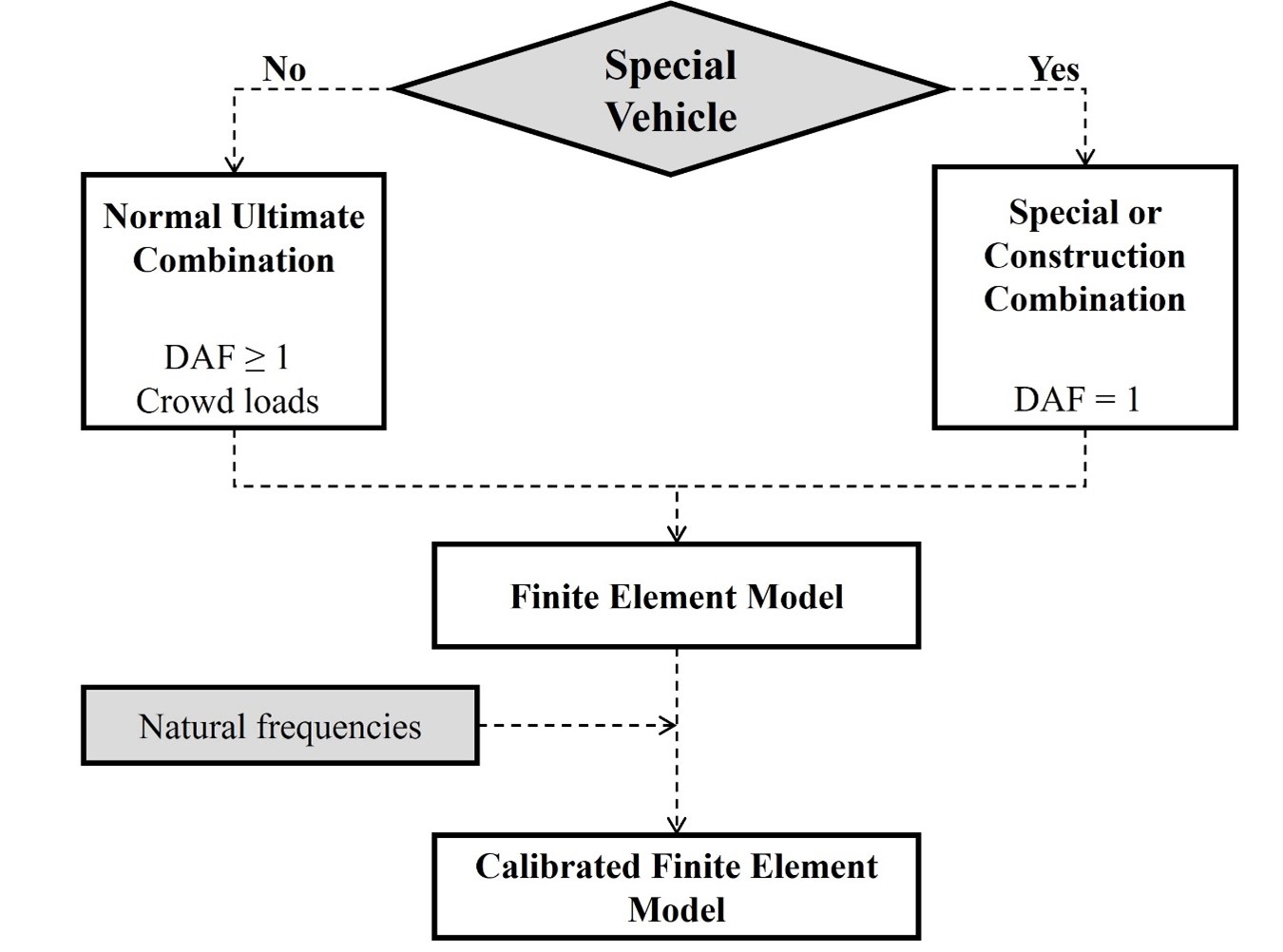
The structural safety of a bridge is evaluated for a specific live load combination, which mostly depends on the vehicle type. The live loads may be divided into usual and unusual loads. Usual loads are standardized design live loads and certified vehicles that usually travel on Brazilian roads. These vehicles travel at high velocity, have lane-specific traffic, and multiple vehicles cross the bridge simultaneously. On the other hand, unusual loads are vehicles that carry extremely high cargo, such as wind turbine blades, and require a distinct transit permit. These unusual live load compositions require special traffic conditions, such as traffic interruption and low-speed crossing. Also, they are positioned in the center of the deck's cross-section. The different traffic conditions lead to different load combinations, as shown in Figure 5.

The load combination factors also depend on the live load and bridge condition. For usual and design vehicles, a Normal Combination may be used with the combination load factors presented in Table 3. Additionally, ABNT NBR 7187 [6] allows for a reduction in these factors when evaluating an existing structure. This reduction may be applied as long as a few criteria are met, which are related to the structure condition and service life. For unusual loads, a special load combination is used with the load combination factors presented in Table 3.
4.1. Finite Element Models
Finite element models should be developed using either inspection data or as-built drawings, incorporating the concrete properties estimated through coring (i.e. compressive strength, modulus of elasticity, and specific weight). Each model includes a set of assumptions tailored to represent the interaction between structural components and the bearing components. For more refined assessments, it is essential to calibrate the models by aligning their dynamic response — specifically, the natural frequencies — with those observed in the actual structure. These frequencies can be obtained through sensors such as accelerometers or even smartphone-based measurements [53]–[55]. The model is considered well-calibrated when the simulated vibration frequencies closely match those recorded from the physical bridge.
5. APPLICATION EXAMPLES
To illustrate the framework's practical application, three existing bridges are assessed. These bridges were selected based on varying age, design, and exposure conditions to provide a test bed for the framework. The framework's application tests its robustness, adaptability, and accuracy in assessing the current state of in-service reinforced concrete bridges. The following sections detail the application and decisions made by the authors within the assessment process.
A few criteria for selecting the bridges include the year of construction and ease of access to the main elements of the bridge. Table 4 shows the information on the bridges selected, including the construction year and design class.
5.1. Condition State and Load Bearing Capacity Reduction Factor
Table 5 shows the condition state of the selected bridges according to a few standards. The chosen standards are the Brazilian bridge inspection regulations and the American, Slovenian, and Lithuanian methods, which will be used for capacity reduction. However, the Brazilian inspection ratings do not lead to capacity reduction estimation because no methodology is calibrated for such condition ratings.
The Teixeiras Stream Bridge had corrosion-induced concrete cover spalling on its girders and columns. Additionally, a half-cell potential test indicated the presence of active corrosion on the column's reinforcement. Although there is severe damage, they do not contribute to structural instability. Thus, a “fair” condition was defined for this bridge.
The Coimbra I viaduct presented minor damage, with a few flexural cracks, that do not compromise the bridge's structural behavior. The Pirapetinga River Bridge also had a few flexural cracks and superficial concrete damage. Mostly, these bridges have no major damages, and both received a “good” condition rating.
5.2. Concrete Strength Estimation
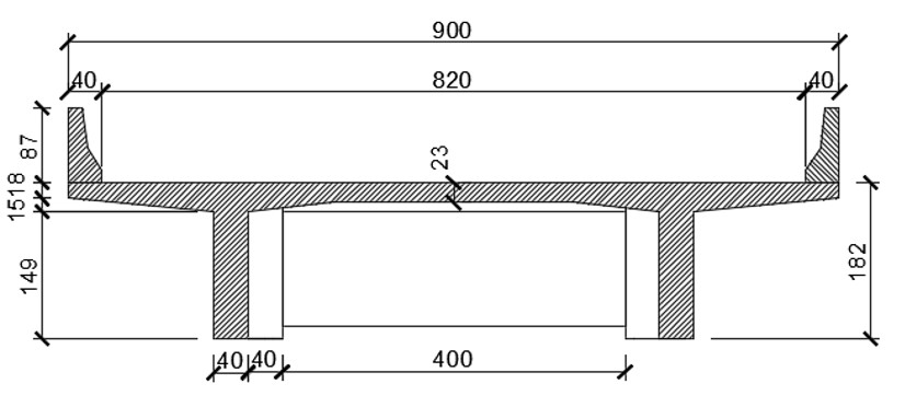
In Approach I, the concrete strength estimation is made either by the minimum standardized requirements or the minimum strength necessary for the concrete struts to resist the design load effects. Table 6 presents the strength estimation in three critical cross-sections along the beam, namely the “bent,” “mid-widening,” and “current” sections. The bent section is the girder cross-section located above the bents; the mid-widening section is the cross-section located in the mid-length of the girder widening near the supports. Finally, the current section is the girder cross-section at the mid-span length.
In Approach II, coring is used to estimate the concrete strength. At least six cylindrical cores with 100 mm diameter and 200 mm height were extracted in each bridge in reduced stress positions along the structure, and the core locations were defined using a profometer equipment test to avoid the rebars. After extraction, the specimens were prepared and tested according to NBR 7680 [57]. This standard quantifies the conversion from core to cylinder strength and allows the assumption that the characteristic strength equals the mean strength for structural safety assessment purposes. Table 7 presents the core’s strength in each bridge alongside the carbonation depth observed in each core.
Comparing the concrete strength estimated in Approach I (Table 6) and Approach II (Table 7) all bridges presented higher strength after coring. The Teixeiras Strem Bridge shows the closest results between Approaches I and II, in which the core’s strength is only 0,6 MPa higher than the one required by the verification of the compressed concrete struts. Coimbra I Viaduct and Pirapetinga River Bridge showed coring strength much higher than the values obtained through Approach I, almost reaching 40 MPa. Thus, the verification of the compressed concrete struts proved to be a good parameter for estimating the minimum compressive strength required by each bridge. However, the results for the other bridges also show that it could lead to a high underestimation of the real compressive strength.
The carbonation data indicates that the carbonation depth has surpassed the concrete cover for all bridges, which means that all bridges are prone to corrosion of the reinforcing bars. The Coimbra I Viaduct and the Teixeiras Strem Bridge were built in the 1980’s decade and have been exposed to environmental conditions for a similar amount of time. In this case, the higher carbonation depth of the Teixeiras Stream bridge might be due to the lower concrete strength, which is directly related to higher porosity, enabling higher carbonation advancement.
The Pirapetinga River Bridge showed high carbonation depth, which was unexpected since the bridge was built in 2013. Despite the Coimbra Viaduct being in service for over 20 years more than the Pirapetinga Bridge, these bridges showed a similar depth, indicating that even though the compressive strength is similar, the CO2 intake is higher for the Pirapetinga Bridge. This difference might be related to the generalized surface damage and high superficial porosity, which result from poor casting conditions and vibrating deficiency, facilitating the advancement of carbonation despite the high compressive strength.
5.3. Redesign
Since none of the bridges had the original construction plans available, they had to be redesigned. Table 8 shows the standards used for estimating the reinforcement area.
At the time of the construction of the Teixeiras and Coimbra bridges, the design of reinforced concrete structures to bending moment was done by guaranteeing the equilibrium between the compression and tensile forces in the cross-section, and the reinforcement area was calculated through Equation 5 (Table 9). In that period, the Brazilian standards were based on the Limit States Method, and the bridge girders were designed as T-beams. For shear design, the Ritter-Mӧrsch original truss theory was the basis for calculating the required stirrup reinforcement area through the strut-and-ties method, as described by Equation 6. Additionally, the cross-section had to be checked for the crushing of the concrete struts through Equation 7.
For the Pirapetinga Bridge, the bending moment design process followed similar concepts, only updating some partial coefficients according to the current standards. For shear design, an extra portion of resistance is provided by mechanisms complementary to the original truss, as shown in Equation 8. The stirrup area is calculated by Equation 9:
The permanent loads were estimated based on the dimensions of the structure measured in the routine inspection, and the load effects due to the permanent loads were calculated using tools that emulate the ones available when the structure was originally designed. The live loads were distributed in the deck cross-section using the influence lines method [60] and then applied to the longitudinal cross-section of the bridge. The permanent and live-load effects were combined into envelope plots, and the design load effects were used to calculate the design parameters (i.e., the concrete strength and the reinforcement area). The redesign processes in explained in detail in [61], [62] and the load effects are shown in Table 10.
Table 11 shows the estimated design data for the bridges by reinforcement type. The estimated reinforcement areas for all the bridges were also assessed by nondestructive testing with a profometer. The number of longitudinal reinforcement bars at the base of the girders, used for resisting bending at midspan, for Teixeiras Bridge and Coimbra Viaduct, measured with the profometer, are 24 and 18, both 25mm rebars, respectively. In both scenarios, the reinforcement area calculated by redesigning the structure overestimates the area observed with the profometer.
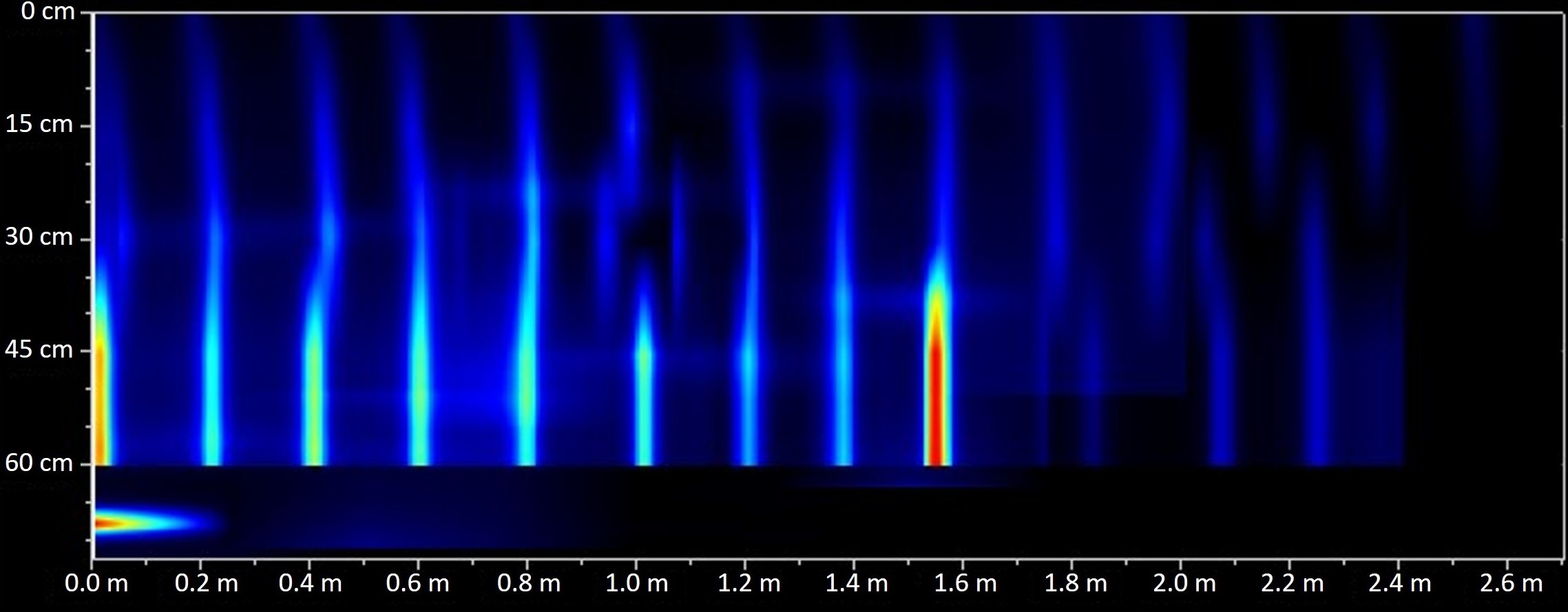
The profometer showed transverse reinforcement of 8mm rebars every 15cm (3.35 cm2/m) for the Coimbra Viaduct, and every 20cm (1.00 cm2/m) for the Teixeiras Bridge, which is shown in Figure 6. The redesign shear reinforcement area was highly overestimated for these bridges, which may indicate that, even though these bridges were constructed after 1980, they might present inclined rebars to resist shear stress. The withdrawal of longitudinal bars into 45 angles to resist shear stress is typical of bridges constructed before 1960.
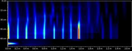
It was not possible to estimate the flexure reinforcement at the support position because the bars are placed within the flange of the T-beam. However, as the reinforcement in midspan was closely estimated by NDT, it is assumed that an accurate stress distribution was achieved for the bridge. Nonetheless, the high bar density on bridge girders may influence the results of NDT reinforcement identification [63].
5.4. Load Bearing Capacity
The load-bearing capacity is estimated by Equation 1 (flexural resistance) and Equation 2 (shear resistance), derived from design code in Brazil [64]. In Approach I, the load-bearing capacity is estimated based on minimum values, while Approach II relies on coring strength combined with NDT results, which results in the bridges' true resistance. The estimated load-bearing capacity for both approaches is shown in Table 12:
The critical load effects in each structure are reflected in the load-bearing capacity values. For the Teixeiras Stream Bridge, the resistance to bending at midspan is higher than the bending over the supports, which is related to the structural configuration of the bridge with one main span and two cantilever spans. This structural configuration could be critical for bending at both locations depending on the ratio between the lengths of the cantilever and the main span. On the other hand, the Coimbra Viaduct has higher bending resistance over the supports, which can also be related to the longitudinal structural configuration. Choosing a continuous beam with multiple supports and two cantilever spans increases the bending moment over the supports and reduces the bending moment at midspan. Lastly, the Pirapetinga River Bridge presents similar bending resistance at both locations, which could be explained by the continuous beam without cantilever spans, which favors a balanced stress distribution.
When comparing the response of both approaches, the estimated load-bearing capacity for the Teixeiras Stream Bridge is very similar for Approaches I and II, irrespective of the stress evaluated, which is related to the concrete strength observed in both approaches. This behavior is not observed on the other bridges that show a significant increase in the load-bearing capacity, especially for shear stress. The Coimbra Viaduct presents a 31% increase in shear resistance, while the Pirapetinga River Bridge shows a 19% increase.
Bending resistance at midspan does not significantly change from Approach I to Approach II due to the design principle for T beams, which requires a large flange width. During the design stage, the increase in concrete strength does not significantly affect the depth of the neutral line due to the width of the flange [65]. A similar effect is observed for resistance estimation, in which the high value of b in Equation 10 prevents a significant change in the final resistance value. On the other hand, for bending over the supports, the web width has a smaller value, and the increase in concrete strength has a more pronounced effect on the neutral line depth and, consequently, on the load-bearing capacity.
5.5. Vehicles
This work assesses the bridge's safety against ten vehicles. There are two standardized design vehicles (Class 36 and TB-450), seven vehicles certified by the Brazilian authorities, and one unusual indivisible load, named PBT-200. Table 13 describes these vehicles by length, width, number of axles, and load by axle. The approved vehicles include dump trucks, semi-trailers, and road trains, while the PBT-200 is an extraordinary vehicle that can carry loads of up to 200 tons which dimensions are presented in [61].
5.6. Finite Element Analysis
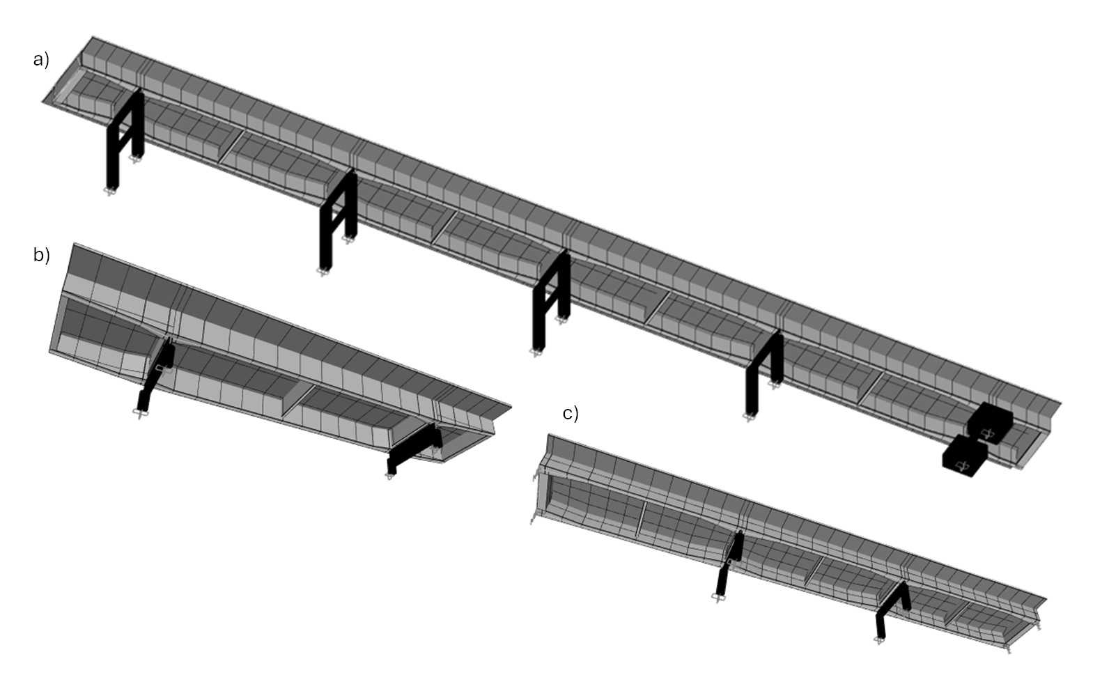
The finite element model was created using the software CSIBridge v.23 (Figure 7). The bridge deck was modeled as a Concrete Tee Beam, and the concrete mechanical properties (e.g., the compressive strength, Young Modulus, and specific weight) were obtained through the cores extracted from the bridges. The FE models were calibrated using the bridge natural frequencies that were estimated using a smartphone by adjusting the structures' mass to match the total mass of the structure-vehicle combination.
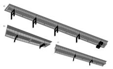
Finite Element Model on CSIBridge: a) Coimbra Viaduct I; b) Teixeiras Stream Bridge; Pirapetinga River Bridge.
According to Cahill et al. [67], with each new generation of smartphones, there is an increasing array of built-in powerful sensors, such as accelerometers. Pravia and Braido [68] utilized a mobile phone equipped with a triaxial accelerometer to measure the vibration characteristics of two overpasses. After extracting acceleration data from the structure, the natural frequencies were determined using the Fast Fourier Transform (FFT). It was concluded that, in addition to being an alternative to traditional vibration testing conducted with purpose-built accelerometers, this method is also a cost-effective option for the quantitative evaluation and maintenance of bridges. Table 14 shows the load effects estimated using the 3D models.
5.7. Rating Factor
The results of the structural assessment of the bridges are shown in Table 15. Approach I is presented based on the capacity reduction methodology and these results are compared to Approach II. The overall evaluation of the results indicates that among the methods used in Model I, the American Method is the least conservative, as it has resulted in the least capacity reduction (Table 5). On the other hand, the Slovenian and Lithuanian methods switch in rigorousness depending on the severity of the damages [69].
Approach II is less conservative than all the methods in Approach I, as it considers more realistic concrete properties. Model I, which bases capacity reduction solely on the condition state, is more conservative than Model II, which uses NDT techniques for damage evaluation and accounts for material properties obtained through supplementary testing. This indicates that supplementary tests are crucial for achieving less conservative results. Approach I could be improved by obtaining the concrete strength used in the bridge designs, and both models could be further enhanced by incorporating the actual reinforcement designed by the engineer.
The proposed methodology is suitable for the Brazilian context, as it suggests the reconstruction of the design, given that most bridges lack this information.
6. DISCUSSION
6.1. Individual Bridge Analysis
6.1.1. Teixeiras Stream Bridge
For Approach I, the Lithuanian method proved to be the most rigorous, and the bridge failed the verification for all live load compositions. For the Slovenian method, the bridge was deemed safe only for two vehicles, including the design live load C36. As mentioned, the American formulation is the most conservative and applies the least reductions to the RF values. As a result, the bridge was deemed safe for all live load compositions.
The Teixeiras Stream Bridge has the smallest RF values among the three analyzed for Approach II. The low RF values are related to the concrete strength estimated from the cores extracted in this bridge. While the other bridges presented a huge increase in concrete strength, this bridge had nearly the same values for both approaches, which implies that this bridge was designed to match the minimum standard values. Nevertheless, for Approach II, the bridge is safe for all live load compositions.
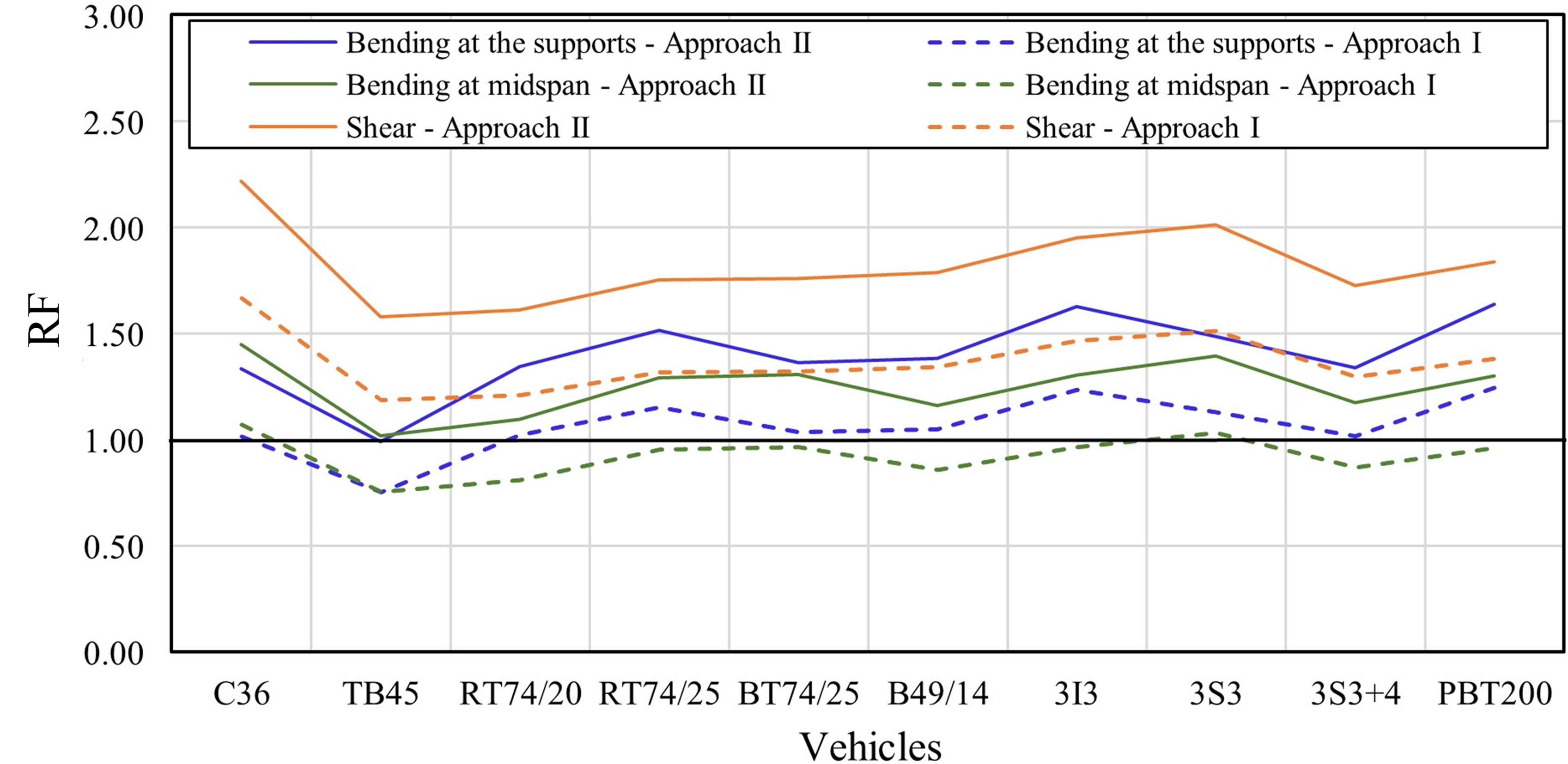
Figure 8 shows the values of rating factors for both approaches and each stress. Shear has the highest RF values for both methods, while bending at midspan is predominantly the critical stress. The exception for flexural resistance is the design vehicles C36 and TB45, which show the lowest RF values for bending at the supports. This bridge was designed to resist mostly bending at midspan (Table 10) with ratios of 0.715 and 0.773 between the maximum bending moment at the supports and at midspan for permanent and live loads, respectively.
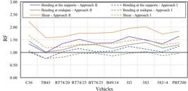
For assessment purposes, a 3D model was built, and the actual behavior of the bridge was observed (Table 14), showing that design techniques slightly overestimated the bending at midspan and underestimated bending over the supports for permanent loads, resulting in a final ratio of 0.639. At the same time, the certified vehicles showed similar behavior, and bending at the supports' influence also reduced with ratios ranging from 0.640 to 0.764. This reduction shows the increase in the impact of bending moment at midspan, ultimately resulting in smaller RF values for these vehicles. On the other hand, the design vehicles - C36 and TB45 - showed an increase in the influence of bending at the supports, and the ratios increased to 0,866 and 0,822. As a result, bending at the supports was the critical stress. This increase in the bending moment at the supports' position could be explained by the reduced length of the standard vehicles, which can fit entirely in the cantilever spans and significantly increase bending stresses.
6.1.2. Coimbra Viaduct
The Coimbra Viaduct has the smallest RF values for Approach I. This bridge fails the assessment for most vehicles in Approach I, except the design live load (C36) evaluated for the Lithuanian (B) and American (C) methods. Approach II analysis contradicted Approach I, indicating the bridge safety for all vehicles. Figure 9 shows the values of rating factors for each stress. Bending at the supports is the critical stress for all vehicles and approaches.
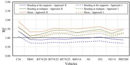
In contradiction with the Teixeiras Bridge, the Coimbra viaduct behavior is heavily influenced by permanent loads. For this bridge, the permanent bending moment for design at the supports is 1.70 times higher than the live load moment (Table 10). As observed for the Teixeiras Bridge, the design techniques overestimate bending at midspan and underestimate bending at the supports. The FEM model showed that permanent stress is actually 1.97 times higher than the live load (Table 14). In this situation, the live load is not significant for the safety assessment, and the only vehicle safe to cross the bridge is the C36, which the bridge was designed to resist. Mostly, this improvement from Approach I to Approach II is related to the concrete compressive strength, which increased from 15 MPa to 39 MPa. However, it was not enough to ensure the structure's safety for most vehicles.
6.1.3. Pirapetinga River Bridge
Since the Pirapetinga River Bridge was constructed in 2013, it was designed to resist the TB-45 loads. For Approach I, the Slovenian method (A) is so conservative that the structure cannot be considered safe for most vehicles (Table 15). On the other hand, only a few live loads have RF smaller than 1.0 in the Lithuanian method (B), and all vehicles are safe in the American method (C) and Approach II.
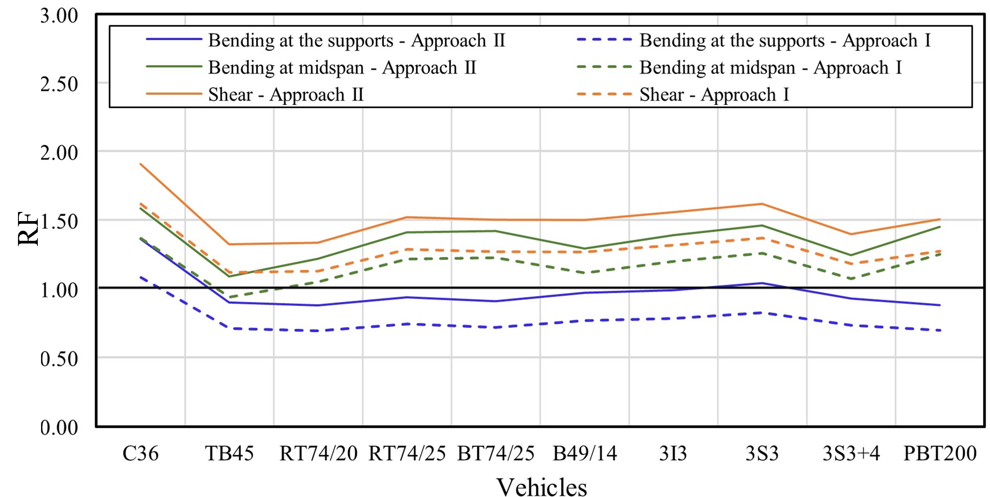
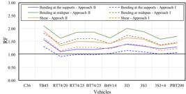
Once again, the design process overestimated the bending moment at midspan and underestimated bending at the supports. For this bridge, the ratio between the bending moment at the supports and midspan was originally estimated as 1.25, but the 3D model provided a 1.40 value (Table 14). On the other hand, most live load configurations have equal values of bending moment in both locations (ratio roughly equal to 1.0). Ultimately, this results in the bending values at the supports being critical and presenting the smallest RF values for this bridge, similar to the others, as can be seen in Figure 10.
6.2. Overall Workflow Evaluation
The overall workflow behavior shows that the safety metric consistently increases when Approach II is used for load rating existing bridges, which indicates the conservatism of Approach I and suggests that the simplification of the analysis does not lead to unsafe results. This behavior attests that the framework allows for a simplified assessment without compromising the safety analysis.
Among the deterioration methods, the Coimbra Viaduct and the Pirapetinga Bridge are in the same condition state and have a similar capacity reduction factor, while the Teixeiras Bridge is more deteriorated and has a higher capacity reduction (smaller capacity coefficient). Comparing the formulations for capacity reduction, the AASHTO factor is the less conservative (higher values), applying smaller reductions to the theoretical capacity and providing a good distinction between the deterioration levels, where the coefficients were 0.95 and 0.85 (Table 5). On the other hand, the Slovenian formulation does not make a similar distinction, and the reduction is more severe for both cases, resulting in reduction factors of 0.87 and 0.84 (Table 5). Overall, the three formulations have a similar rigorousness for lower condition states (Teixeiras Bridge), and the main difference is for bridges in better conditions, where the reduction factors range from 0.95 (American) to 0.87 (Slovenian). The analysis of the deterioration factors indicates their crucial role in assessing existing structures. Thus, it is recommended to adopt formulations calibrated to situations similar to the bridges under evaluation. Further research should be conducted to calibrate a deterioration coefficient to represent the condition of Brazilian bridges
When a bridge fails the assessment proposed in this work, it does not mean that the bridge is unsafe, but further studies and more refined techniques are required. There are some options for improving the results of a failed analysis, such as increasing the reliability of the data introduced in the assessment or enhancing the tools.
The use of load tests is a common practice in the assessment of existing bridges [70]–[73]. Diagnostic load tests are used to observe the bridge behavior, measure the structure responses to a known load, and calibrate the FEM models. When such tests are conducted, a complete analysis of the structure is crucial and requires extensive instrumentation of the bridge. Load tests also enable the use of more refined modeling techniques, such as the use of non-linear FEM [74].
Another option to improve the reliability of the results is to update the live load models used in the assessment procedure. Several countries do not provide a live load model for the assessment of existing bridges and rely on the design live load, which is usually conservative. The updating of the live load models should be conducted based on local traffic measurements [12], [14] and may account for the structure's reduced remaining service life [13], [75].
Finally, reliability analysis is also an option to improve the assessment. The estimation of the uncertainties through random variables allows for a failure probability analysis, which is a more reliable metric and involves the knowledge of several geometric and material properties.
6.3. Recommendations for practice
Based on the proposed workflow and the application examples, some practice recommendations can be defined. Firstly, for bridges without construction plans, a series of information is required before starting the structural assessment. A piece of essential information is the year of construction of the bridge, or at least the construction period, to determine the standards in force at the time. In this case, when there is no information on the system, it is vital to know the structural systems used in past decades because bridges built around the same period usually share several common features. A last resource for obtaining information on the construction year is to contact the local population, which may know important historical facts about the structure.
Concerning the assessment of the condition state, the use of non-destructive techniques seems to be imperative for assessing the damage extent, especially for corrosion spread identification. Core extraction provides information on both the concrete strength and the carbonation depth, which is indicative of the degradation advancement in the structure. NDT is recommended for obtaining information on the steel area, even though it may not result in exact reinforcement identification. In this case, consulting old standards seems to be a reliable way of assessing the structure reinforcement configuration and, ultimately, calculating the load-bearing capacity.
Another parameter that should be considered when assessing the safety of existing bridges is the finite element model calibration. Several studies have shown that smartphones can collect acceleration data for identifying the bridge vibration frequencies. Thus, no refined equipment is necessary for the preliminary calibration of the model, which allows its application on routine verifications. On the other hand, more in-depth studies may require advanced bridge instrumentation to identify the vibration modes and other information used for model calibration.
Finally, in case a bridge fails the verification based on the proposed framework, the structure should be further assessed using more refined techniques, such as non-linear FEM or reliability analysis. The updating of the live load models based on local traffic information is also an option for further assessing the safety of a bridge. Ultimately, a load test could also describe the structure's behavior and be used to calibrate more refined models.
7. CONCLUSIONS
The framework proposed in this work is suitable for the Brazilian scenario for proposing the redesign of the design parameters since most bridges do not have original design plans. Additionally, it enables a more complete structure analysis without appealing to complex experiments such as a loading test.
Approach I uses minimum design criteria to estimate the missing data and the bridge load-bearing capacity based on these minimum parameters. Additionally, Approach I relies on the condition state to estimate the reduction of the load-bearing capacity. On the other hand, Approach II uses NDT to assess damage extension and coring for concrete strength estimation. Even though Approach II also estimates the missing data based on minimum standard requirements, it also compares the results with NDT (reinforcement area estimation) and coring (concrete strength estimation). Thus, the load-bearing capacity estimation relies on data extracted from the real structure, which makes this approach closer to its actual behavior. As a result, Approach II has proven to be less conservative than Approach I, indicating higher Rating Factor values.
Concrete compressive strength estimation is a vital step for Approach II application. This work highlights the increase in the load-bearing capacity estimated through both approaches, and it mainly depends on the increase in concrete strength. The closer the estimated strength to the actual concrete strength, the closer the load-bearing capacity will be to the actual resistance of the bridge. Estimating accurate concrete strength is especially beneficial for this framework because the example application showed that old design strategies tend to underestimate the bending moment at the support location.
The use of a 3D finite element model enabled a comprehensive understanding of the load effects distribution along the bridge cross-section and longitudinal axis. For all bridges analyzed, the analytical tools used for bending moment estimation in past decades tend to overestimate the bending moment at midspan and underestimate the moment at the support location. The bending moment at the support positions has proved to be critical, irrespective of the approach. Mostly, this is related to the simplifications made during the design process, which underestimate both the dead and live load effects. As a result, all bridges presented load-bearing capacity inferior to what was required.
Thus, this work contributes not only by proposing a simple framework that could be applied prior to load testing but also highlights a few characteristics of bridges designed in past decades that could be vital for existing structures assessment.
ACKNOWLEDGEMENTS
This study was financed by the Departamento Nacional de Infraestrutura e Transporte (DNIT) through the DNIT/UFV Project 291 of TED No. 00703/2020. The authors also acknowledge the support provided by the Federal University of Viçosa (UFV) Department of Civil Engineering. The authors also thank the research groups TechBIM/CNPq and SICon/CNPq for the infrastructure and collaboration. Finally, thanks are also due to the Construction Materials Laboratory, and the Mechanical Tests Laboratory.
-
Financial support:
This study was financed by the Departamento Nacional de Infraestrutura de Transportes – Brasil (DNIT), No. 00703/2020. The authors also acknowledge the support provided by the Civil Engineering Department of the Federal University of Viçosa (UFV).
-
Data Availability:
Due to the nature of this research, which includes real structures, participants of this study do not agree for their data to be shared publicly, so supporting data are not available.
-
How to cite:
M. S. Andrade et al., “A framework for load rating existing reinforced concrete bridges,” Rev. IBRACON Estrut. Mater., vol. 18, no. 4, e18408, 2025, https://doi.org/10.1590/S1983-41952025000400008
REFERENCES
-
1 F. J. R. Mascarenhas, R. C. Carvalho, and J. A. P. Vitório, “An analysis of the current conditions of bridges and viaducts of Brazilian highways,” in Anais 61º Congr. Bras. Concr., Oct. 2019. Accessed: Oct. 29, 2024. [Online]. Available: https://www.researchgate.net/publication/344858553
» https://www.researchgate.net/publication/344858553 - 2 P. T. C. Mendes, “Contribuições para um modelo de gestão de pontes de concreto aplicado à rede de rodovias brasileiras,” Ph.D. dissertation, Esc. Polit., Univ. São Paulo, São Paulo, 2009.
-
3 R. S. Guimarães, M. S. P. L. Perlingeiro, L. A. V. Carneiro, and F. M. S. Júdice, "Normas técnicas brasileiras sobre projeto de pontes em concreto armado: considerações e evolução," Braz. J. Dev., vol. 6, no. 10, pp. 77356–77369, 2020, http://doi.org/10.34117/bjdv6n10-240
» http://doi.org/10.34117/bjdv6n10-240 - 4 Departamento Nacional de Infraestrutura de Transportes, Manual de Inspeção de Pontes Rodoviárias, 2nd ed. Rio de Janeiro: DNIT, 2004.
-
5 P. Junges, R. C. A. Pinto, and L. F. F. Miguel, "B-WIM systems application on reinforced concrete bridge structural assessment and highway traffic characterization," Rev. IBRACON Estrut. Mater., vol. 10, no. 6, pp. 1338–1365, Nov. 2017, http://doi.org/10.1590/s1983-41952017000600010
» http://doi.org/10.1590/s1983-41952017000600010 - 6 Associação Brasileira de Normas Técnicas, Projeto de Pontes, Viadutos e Passarelas de Concreto, ABNT NBR 7187, 2021.
- 7 American Association of State Highway and Transportation Officials, The Manual for Bridge Evaluation Washington: AASHTO, 2018. Accessed: Oct. 29, 2024. [Online]. Available: www.transportation.org
-
8 C. V. Aguilar, D. V. Jáuregui, C. M. Newtson, B. D. Weldon, and T. M. Cortez, "Load rating a prestressed concrete double T-beam bridge without plans by field testing," Transp. Res. Rec., vol. 2522, no. 1, pp. 90–99, 2015, http://doi.org/10.3141/2522-09
» http://doi.org/10.3141/2522-09 -
9 A. Bagheri, M. Alipour, O. E. Ozbulut, and D. K. Harris, "A nondestructive method for load rating of bridges without structural properties and plans," Eng. Struct., vol. 171, pp. 545–556, Sept. 2018, http://doi.org/10.1016/j.engstruct.2018.05.114
» http://doi.org/10.1016/j.engstruct.2018.05.114 -
10 A. M. Cuaron, D. V. Jáuregui, and B. Weldon, "Simple procedure for load rating reinforced concrete slab bridges without plans research objective and literature review," J. Perform. Constr. Facil., vol. 34, no. 5, pp. 04020083, 2020, http://doi.org/10.1061/(ASCE)CF.1943-5509.0001476
» http://doi.org/10.1061/(ASCE)CF.1943-5509.0001476 - 11 S. Zadlauskas and M. Augonis, "Methodology for calculation of bridge safety factor in Lithuania," Mater. Sci. Eng., vol. 1202, no. 1, pp. 012030, 2021.
-
12 European Cooperation in Science and Technology, Procedures Required for the Assessment of Highway Structures, COST 345, 2007. Accessed: Oct. 29, 2024. [Online]. Available: http://www.cordis.lu/cost-transport/home.html
» http://www.cordis.lu/cost-transport/home.html -
13 K. Schellenberg, M. Chèvre, and M. Alvarez, "Assessment of bridges on the Swiss national roads," Struct. Eng. Int. J. Int. Assoc. Bridge Struct. Eng., vol. 23, no. 4, pp. 402–410, 2013, http://doi.org/10.2749/222137813806521162
» http://doi.org/10.2749/222137813806521162 -
14 E. Brühwiler, T. Vogel, T. Lang, and P. Lüchinger, "Swiss standards for existing structures," Struct. Eng. Int., vol. 22, no. 2, pp. 275–280, May 2012, http://doi.org/10.2749/101686612X13291382991209
» http://doi.org/10.2749/101686612X13291382991209 -
15 J. Vičan, J. Odrobiňák, and J. Gocál, "Determination of Road Bridge Load -Carrying Capacity," Civ. Environ. Eng., vol. 17, no. 1, pp. 286–297, Jun. 2021, http://doi.org/10.2478/cee-2021-0030
» http://doi.org/10.2478/cee-2021-0030 -
16 C. R. Oliveira and A. L. Moreno Jr., "Considerações sobre prova de carga em estruturas de concreto," Rev. Esc. Minas, vol. 60, no. 1, pp. 29–36, 2007, http://doi.org/10.1590/S0370-44672007000100005
» http://doi.org/10.1590/S0370-44672007000100005 - 17 L. Souza, P. Silva, E. Figueiredo, A. Neto, P. Prazeres, and M. Ferreira, “Avaliação da condição estrutural de uma ponte construída sobre estruturas existentes na Rodovia Transamazônica,” in XII Congr. Bras. Pontes e Estrut., Jun. 2021.
-
18 R. R. A. Briones, “Bridge load rating: a general procedure for load rating bridges without plans,” M.S. thesis, Purdue Univ., West Lafayette, 2018. [Online]. Available: https://docs.lib.purdue.edu/open_access_dissertations/1683
» https://docs.lib.purdue.edu/open_access_dissertations/1683 - 19 Associação Brasileira de Normas Técnicas, Cálculo e Execução de Obras de Concreto Armado, ABNT NB 1, 1940.
- 20 Associação Brasileira de Normas Técnicas, Cálculo e Execução de Obras de Concreto Armado, ABNT NB 1, 1960.
- 21 Associação Brasileira de Normas Técnicas, Projeto e Execução de Obras de Concreto Armado, ABNT NB 1, 1978.
- 22 Associação Brasileira de Normas Técnicas, Projeto e Execução de Obras de Concreto Armado, ABNT NBR 6118, 1980.
- 23 Associação Brasileira de Normas Técnicas, Ações e Segurança nas Estruturas – Procedimento, ABNT NBR 8681, 2004.
- 24 J. M. Araújo, Estruturas de Concreto: A Resistência à Compressão e Critérios de Ruptura para o Concreto, vol. 1. Rio Grande: DUNAS, 2001.
- 25 Associação Brasileira de Normas Técnicas, Projeto de Estruturas de Concreto – Procedimento, ABNT NBR 6118, 2003.
- 26 Associação Brasileira de Normas Técnicas, Execução de Estruturas de Concreto – Procedimento, ABNT NBR 14931, 2004.
- 27 Associação Brasileira de Normas Técnicas, Concreto para Fins Estruturais – Classificação pela Massa Específica, por Grupos de Resistência e Consistência, ABNT NBR 8953, 2015.
- 28 Associação Brasileira de Normas Técnicas, Projeto de Estruturas de Concreto – Procedimento, ABNT NBR 6118, 2014.
- 29 Associação Brasileira de Normas Técnicas, Barras para Concreto Armado, ABNT EB 3, 1967.
- 30 Associação Brasileira de Normas Técnicas, Barras e Fios de Aço Destinados a Armaduras para Concreto Armado, ABNT NBR 7480, 1996.
- 31 Associação Brasileira de Normas Técnicas, Aço Destinado a Armaduras para Estruturas de Concreto Armado – Especificação, ABNT NBR 7480, 2007.
- 32 P. F. Silva, M. A. N. Brito, I. C. Santos, R. S. Y. C. Silva, and B. E. Emidio So., “Efeitos da mudança da NBR 7188:2013 nos projetos de pontes. Estudo de caso: projeto de recuperação da ponte sobre o Rio Correias na BR 101/SC,” in VII Congr. Bras. Pontes e Estrut., Rio de Janeiro, 2014.
- 33 Associação Brasileira de Normas Técnicas, Cálculo e Execução de Pontes de Concreto Armado, ABNT NB 2, 1946.
- 34 Associação Brasileira de Normas Técnicas, Cálculo e Execução de Pontes de Concreto Armado, ABNT NB 2, 1961.
- 35 Associação Brasileira de Normas Técnicas, Carga Móvel Rodoviária e de Pedestres em Pontes, Viadutos, Passarelas e Outras Estruturas, ABNT NBR 7188, 2013.
- 36 Associação Brasileira de Normas Técnicas, Carga móvel em Pontes Rodoviárias, ABNT NBR 6 1946, 1946.
- 37 Associação Brasileira de Normas Técnicas, Cargas Móveis em Pontes Rodoviárias, ABNT NBR 6, 1960.
- 38 Associação Brasileira de Normas Técnicas, Carga Móvel para Pontes Rodoviárias e Passarelas de Pedestres, ABNT NBR 7188, 1984.
-
39 A. G. Medeiros, M. V. V. A. Sá, J. N. Silva Fo., and M. A. S. Anjos, “Aplicação de metodologias de inspeção em ponte de concreto armado," Ambient. Constr., vol. 20, no. 3, pp. 687–702, Jul. 2020, http://doi.org/10.1590/s1678-86212020000300453
» http://doi.org/10.1590/s1678-86212020000300453 -
40 M. Alsharqawi, T. Zayed, and S. Abu Dabous, "Integrated condition rating and forecasting method for bridge decks using Visual Inspection and Ground Penetrating Radar," Autom. Construct., vol. 89, pp. 135–145, May 2018, http://doi.org/10.1016/j.autcon.2018.01.016
» http://doi.org/10.1016/j.autcon.2018.01.016 - 41 Departamento Nacional de Infraestrutura de Transportes, Inspeções em Pontes e Viadutos de Concreto Armado e Protendido – Procedimento, DNIT 010, 2004.
- 42 Associação Brasileira de Normas Técnicas, Inspeção de Pontes, Viadutos e Passarelas – Procedimento, ABNT NBR 9452, 2023.
- 43 A. C. V. Giovanetti and R. C. Pinto, “Avaliação da condição de uma ponte: estudo de caso,” in VII Congr. Bras. Pontes e Estrut., Rio de Janeiro, 2014.
-
44 J. Bennetts, G. Webb, S. Denton, P. J. Vardanega, and N. Loudon, “Quantifying uncertainty in visual inspection data,” in Maintenance, Safety, Risk, Management and Life-Cycle Performance of Bridges, N. Powers, D. Frangopol, R. Al-Mahaidi, C. Caprani, Eds., London: CRC Press, 2018, pp. 2252–2259, http://doi.org/10.1201/9781315189390-306
» http://doi.org/10.1201/9781315189390-306 -
45 P. J. Vardanega, T. Tryfonas, G. Gavriel, D. T. Nepomuceno, M. Pregnolato, and J. Bennetts, “A review of recent research on visual inspection processes for bridges and the potential uses of AI,” in Bridge Maintenance, Safety, Management, Digitalization and Sustainability, J. S. Jensen, D. M. Frangopol, J. W. Schmidt, Eds., London: CRC Press, 2024, pp. 3573–3580, http://doi.org/10.1201/9781003483755-422
» http://doi.org/10.1201/9781003483755-422 -
46 D. T. Nepomuceno, P. J. Vardanega, M. Pregnolato, T. Tryfonas, and J. Bennetts, "Viability of bridge inspectors determining defect ratings using photographic images," Infrastruct. Asset Manage., vol. 10, no. 3, pp. 144–156, Sep. 2023, http://doi.org/10.1680/jinam.23.00004
» http://doi.org/10.1680/jinam.23.00004 - 47 F. C. Lea and C. R. Middleton, Reliability of Visual Inspection of Highway Bridges Cambridge: University of Cambridge, 2002.
- 48 L. F. Simões, P. F. Rodrigues, and D. C. C. Pinheiro, “Análise Crítica dos métodos de inspeção da ABNT NBR 9452:2019,” in XII Congr. Bras. Pontes e Estrut., 2021.
- 49 Federal Highway Administration, Recording and Coding Guide for the Structure Inventory and Appraisal of the Nation’s Bridges Washington: FHWA, 1995.
- 50 American Association of State Highway and Transportation Officials, LRFD Bridge Design Specifications, Part I : Sections 1-6, 8th ed. Washington: AASHTO, 2017.
- 51 M. Kušar and J. Šelih, "Analysis of bridge condition on state network in Slovenia," Gradjevinar, vol. 66, no. 9, pp. 811–822, Sep. 2014, http://dx.doi.org/10.14256/JCE.1047.2014.
- 52 A. Žnidarič et al., “Management of Bridges in Slovenia,” in XXV World Road Congr., Seoul, 2015.
-
53 A. Elhattab, N. Uddin, and E. OBrien, "Extraction of bridge fundamental frequencies utilizing a smartphone mems accelerometer," Sens. Switz., vol. 19, no. 14, pp. 3143, Jul. 2019, http://doi.org/10.3390/s19143143
» http://doi.org/10.3390/s19143143 -
54 J. D. Sitton, D. Rajan, and B. A. Story, "Bridge frequency estimation strategies using smartphones," J Civ Struct Health Monit, vol. 10, no. 3, pp. 513–526, Jul. 2020, http://doi.org/10.1007/s13349-020-00399-z
» http://doi.org/10.1007/s13349-020-00399-z -
55 A. K. Ndong, M. S. Dizaji, M. Alipour, O. E. Ozbulut, and D. K. Harris “Load rating of a reinforced concrete T-Beam bridge through ambient vibration testing and finite element model updating,” in Proc. 36th IMAC, Conf. & Expos. Struct. Dyn. 2018, S. Pakzad, Ed., 2018. [Online]. Available: http://www.springer.com/series/8922
» http://www.springer.com/series/8922 - 56 Associação Brasileira de Normas Técnicas, Inspeção de Pontes, Viadutos e Passarelas de Concreto – Procedimento, ABNT NBR 9452, 2019.
- 57 Associação Brasileira de Normas Técnicas, Concreto – Extração, Preparo, Ensaio e Análise de Testemunhos de conceto, ABNT NBR 7680-1, 2015.
- 58 Associação Brasileira de Normas Técnicas, Projeto de Estruturas de Concreto – Procedimento, ABNT NBR 6118, 2007.
- 59 Associação Brasileira de Normas Técnicas, Projeto de Pontes de Concreto Armado e de Concreto Protendido – Procedimento, ABNT NBR 7187, 2003.
- 60 H. I. Longo, “Esforços máximos em pontes tipo grelha,” M.S. thesis, Univ. Fed. Rio de Janeiro, Rio de Janeiro, 1979.
- 61 M. A. N. Cardoso, “Metodologia de avaliação da segurança estrutural de pontes de concreto armado,” M.S. thesis, Univ. Fed. Viçosa, Viçosa, 2022.
- 62 M. S. Andrade, M. A. N. Cardoso, D. S. Oliveira, C. F. S. Santos, J. C. L. Ribeiro, and J. M. F. Carvalho, “The changes over time in the design criteria of reinforced concrete bridges according to Brazilian Standards,” in 64º Congr. Bras. Concr., Florianópolis, Oct. 2023.
- 63 M. S. Andrade et al., “Aplicabilidade de ensaios não-destrutivos para obtenção de dados de projeto e avaliação da condição estrutural de pontes de concreto armado,” in XIV Congr. Bras. Pontes e Estrut., Rio de Janeiro, May 2023.
- 64 Associação Brasileira de Normas Técnicas, Projeto de Estruturas de Concreto, ABNT NBR 6118, 2023.
- 65 M. S. Andrade et al., “Metodologia de avaliação estrutural de longarinas de pontes de concreto armado sem dados de projeto: uma análise probabilística,” in XIV Congr. Bras. Pontes e Estrut., Rio de Janeiro, May 2023.
- 66 M. K. El Debs et al., Análise das Consequências do Tráfego de CVCs (Combinações de Veículos de Carga) sobre as Obras de Arte Especiais da Rede Viária do DER-SP São Carlos: Universidade de São Paulo, 2001.
- 67 P. Cahill, L. Quirk, P. Dewan, and V. Pakrashi, "Comparison of smartphone accelerometer applications for structural vibration monitoring," Adv. Comput. Des., vol. 4, no. 1, pp. 1–13, Jan. 2019, http://dx.doi.org/10.12989/acd.2019.4.1.001.
-
68 Z. M. C. Pravia and J. D. Braido, "Measurements of bridges’ vibration characteristics using a mobile phone," Rev. IBRACON Estrut. Mater., vol. 8, no. 5, pp. 721–743, Oct. 2015, http://doi.org/10.1590/S1983-41952015000500009
» http://doi.org/10.1590/S1983-41952015000500009 - 69 M. S. Andrade, M. A. N. Cardoso, D. S. Oliveira, C. F. R. Santos, J. C. L. Ribeiro, and J. M. F. Carvalho, “Avaliação metodológica da segurança estrutural de pontes de concreto armado: estudos de caso,” in 64º Congr. Bras. Concr., Florianópolis, Oct. 2023.
-
70 E. O. L. Lantsoght, "Assessment of existing concrete bridges by load testing: barriers to code implementation and proposed solutions," Struct. Infrastruct. Eng., vol. 20, no. 7–8, pp. 1002–1014, 2024, http://doi.org/10.1080/15732479.2023.2264825
» http://doi.org/10.1080/15732479.2023.2264825 -
71 E. O. L. Lantsoght, C. van der Veen, A. Boer, and D. A. Hordijk, "State-of-the-art on load testing of concrete bridges," Eng. Struct., vol. 150, pp. 231–241, Nov. 2017, http://doi.org/10.1016/j.engstruct.2017.07.050
» http://doi.org/10.1016/j.engstruct.2017.07.050 -
72 G. I. Zarate Garnica, E. O. L. Lantsoght, and Y. Yang, "Monitoring structural responses during load testing of reinforced concrete bridges: a review," Struct. Infrastruct. Eng., vol. 18, no. 10–11, pp. 1558–1580, 2022, http://doi.org/10.1080/15732479.2022.2063906
» http://doi.org/10.1080/15732479.2022.2063906 -
73 S. Alampalli et al., "Bridge load testing: state-of-the-practice," J. Bridge Eng., vol. 26, no. 3, pp. 03120002, Mar. 2021, http://doi.org/10.1061/(ASCE)BE.1943-5592.0001678
» http://doi.org/10.1061/(ASCE)BE.1943-5592.0001678 -
74 N. Bagge, M. Plos, and C. Popescu, "A multi-level strategy for successively improved structural analysis of existing concrete bridges: examination using a prestressed concrete bridge tested to failure," Struct. Infrastruct. Eng., vol. 15, no. 1, pp. 27–53, Jan. 2019, http://doi.org/10.1080/15732479.2018.1476562
» http://doi.org/10.1080/15732479.2018.1476562 - 75 M. Ralbovskyet al., Recommendations on the Use of Results of Monitoring on Bridge Safety Assessment and Maintenance Warsaw: ARCHES, 2009.
Edited by
-
Editors:
Túlio Bittencourt, Daniel Cardoso.