 Assessment of printing direction in flexural tests of 3D printed reinforced concrete beams
Abstract
Abstract In Brazil, research on 3D-printed mortar remains nascent, with limited progress in structural applications. In this context, the present study aims to evaluate the structural impact of the printing direction on 3D-printed mortar beams. The study compares three types of beams: those printed in the longitudinal direction, those printed in the transverse direction, and conventionally cast beams. All beams were longitudinally reinforced and subjected to flexural testing. As anticipated, the cast beams exhibited superior strength compared to the beams printed with layers oriented longitudinally along the beam's axis. Beams printed with layers in the transverse direction demonstrated a significant reduction in strength, attributed to weakened interlayer bonding, creating preferential crack propagation paths.
Keywords:
3DPC; concrete printing; bending tests; printed beams
Resumo
Resumo No Brasil, o estudo sobre argamassa impressão em 3D ainda é incipiente, com pouco avanço em aplicações estruturais. Isto posto, este trabalho busca avaliar o impacto estrutural da direção de impressão em vigas de argamassa impressas em 3D, propondo uma comparação entre três tipologias de vigas: as impressas na direção longitudinal e transversal e as moldadas de maneira convencional. Todas as vigas foram armadas longitudinalmente e submetidas a ensaios de flexão. Como esperado, as vigas moldadas apresentaram resistência superior às vigas impressas com cordões longitudinais ao eixo da viga. Já as vigas impressas com cordões na direção transversal tiveram penalização expressiva na resistência, atribuída à menor adesão entre as camadas, o que criou caminhos preferenciais para a propagação de fissuras.
Palavras-chave:
3DPC; impressão de concreto; ensaios de flexão; vigas de impressão 3D
1 INTRODUCTION
Additive manufacturing of cementitious materials has become increasingly prevalent in civil construction as an alternative to traditional methods, offering advantages like higher productivity, reduced material/labor costs, improved sustainability, and energy efficiency. It also enables the development of projects with complex geometries and ensures greater adaptability to functional architecture and modular construction [1]. Two main types of concrete printers worldwide exist gantry-type and pivoting articulated arms. The robotic arms can perform tasks beyond additive manufacturing, such as painting, finishing, and assembly [2].
It is important to note that the primary method for strengthening 3D-printed parts is adding layers of plastically deformable material wires [3]. However, the interfaces between these layers can become weak points in the printed parts, compromising their mechanical performance [4]. These interfaces create a path of least resistance to potential failures. Incorporating reinforcements in areas subject to tension in structural components is crucial. While including fibers or reinforcements aligned with the primary stresses can enhance the strength of reinforced 3D-printed parts [3], they are unsuitable for replacing load-bearing structural elements. Therefore, further research and development of compatible reinforcement strategies with the 3D printing process are imperative.
Traditional reinforced concrete structures, such as beams, steel bars, or reinforcement meshes, are used in the tension zone to withstand bending. Incorporating high-tensile-strength materials into 3D-printed concrete is essential to transfer of tensile stresses post-cracking and maintain the structural component's ductile behavior. Hence, developing methodologies for producing elements with structural purposes is crucial while preserving the design freedom provided by 3D printing [3].
The present study will examine 3D-printed beams reinforced with steel reinforcement, analyzing the printing orientation and bending behavior compared to a conventionally cast reinforced concrete beam molded using traditional formwork.
2 3D PRINTING OF CONCRETE
3D printing of cement materials needs concrete study, and material selection focuses on identifying the properties in fresh and hardened states. This is vital as printing parameters like printer nozzle size, extrusion pressure, printing speed, element size, and shape play a crucial role. Furthermore, the cementitious material must possess adequate strength to ensure stability during the printing and usage phases.
An appropriate cementitious material should be malleable and extrudable, fluid, with a suitable setting time, low shrinkage, and good mechanical strength [4].
In summary:
-
extrudability is the material's ability to be continuously supplied within the extrusion system [1].
-
the ability to maintain its extruded shape under its weight and the pressure of the upper layers is known as buildability. This can be controlled by viscosity-modifying agents and optimizing the setting time [1].
-
shrinkage can impact the bond between printed layers, causing detachment. Adding minerals, a low water/cement ratio, and more fine aggregate can reduce shrinkage [1].
-
the mechanical properties of 3D-printed cementitious materials exhibit anisotropic behavior, meaning that the strength depends on each layer's deposition direction. The highest mechanical properties are achieved in the direction parallel to the printing direction (longitudinal). On the other hand, properties measured in the perpendicular direction (90º) to the printing direction are lower [1].
In this last case, the mechanical properties of 3D printing have generally been studied exclusively in cementitious parts, meaning they are unreinforced.
Salazar et al. [1] suggest that adding randomly dispersed short fibers is the most effective method for reducing the anisotropic behavior of printed elements. However, while adding fibers helps mitigate this behavior, it does not eliminate it.
Although 3D-printed concrete maintains higher compressive strength than tensile strength, its unique internal structure gives it mechanical properties different from conventionally cast concrete [5]. The primary difference lies mainly in the formation process of the printed elements, leading to anisotropic behavior, which directly influences their performance [5], [6].
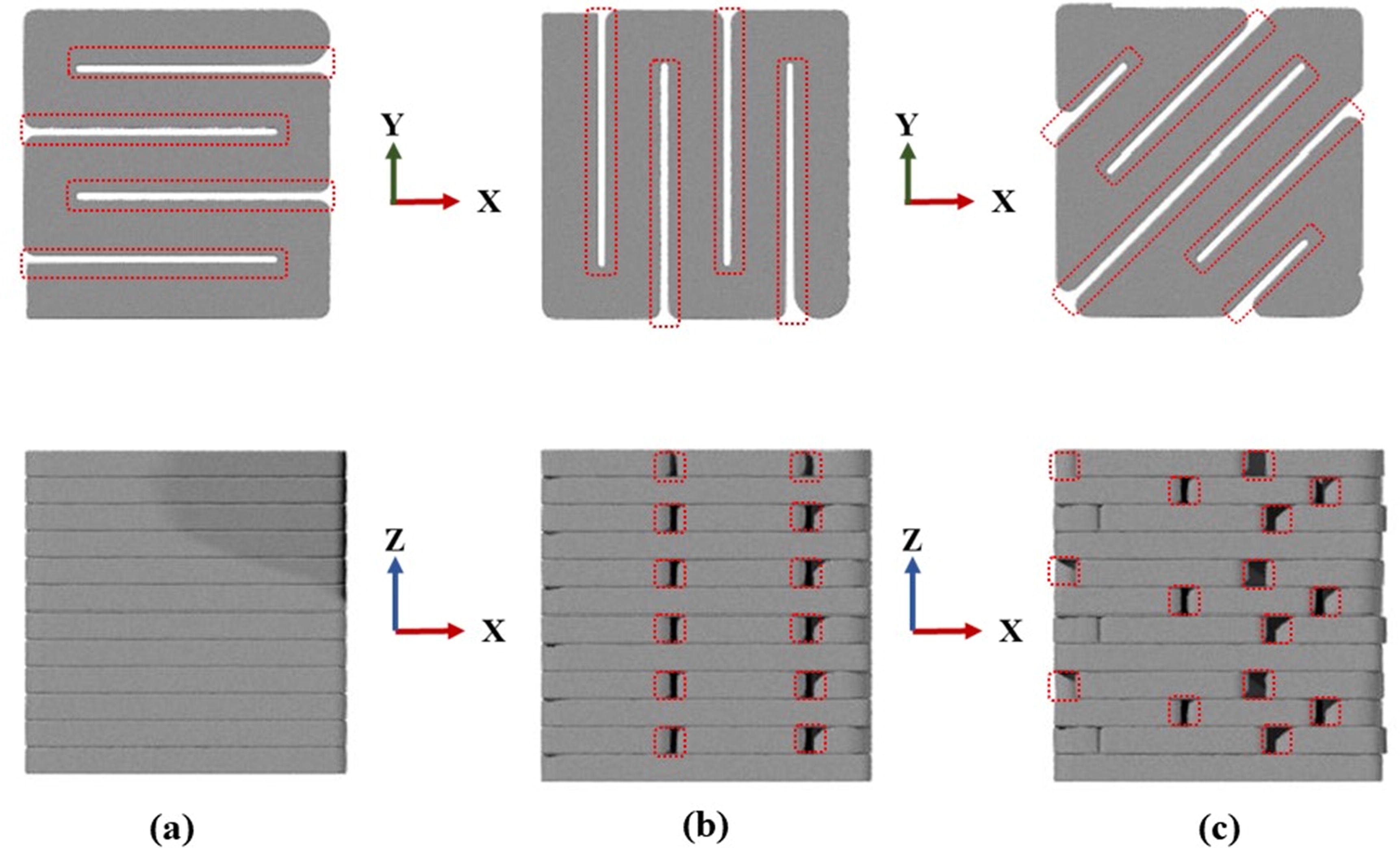
When overlapping and aligned layers are deposited in 3D-printed concrete, voids are present. However, the overlapping layers reduce voids by exerting compressive pressure on the lower layer. In contrast, aligned layers contain more voids as they do not experience the same phenomenon, as illustrated in Figure 1 [7].

Diagram of impressions (a) Horizontal, (b) Vertical, and (c) Diagonal, highlighting the formation of voids (indicated in red) [8].
These interfaces between printed layers are called "cold joints" and are generally the weakest link in printed structures, primarily due to the formation of voids. This leads to pronounced anisotropy and affects printed elements' mechanical performance and durability [4].
On the other hand, studies conducted with highly ductile 3D-printed concrete have shown that the presence of some voids dispersed the stresses transmitted from the lower layer, resulting in an increased cracking range and preventing premature failure of the specimen when tested in the direction perpendicular to the printing direction [9].
Thus, due to the anisotropic behavior of 3D-printed concrete, the mechanical properties of this material vary according to the direction in which the layers are printed and typically show lower values when subjected to loads applied perpendicular to the printing direction [1], [7], [10].
2.1 Printed structural elements
Reinforcement methods can be added to the printed structure to meet structural integrity requirements for load-bearing and service conditions. Thus, external reinforcement methods, such as prestressing cables, passive reinforcement, printing elements with voids for later reinforcement insertion and manual grouting, fibers, and flexible wires, can be used for the printed structure [3], [11].
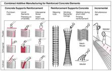
The major challenge in the additive manufacturing of cementitious composites is using reinforcement provided by rebar or other components. Studies such as those by Kloft et al. [3] propose a systematic approach to combining additive manufacturing with reinforced concrete elements. By using 3D concrete printing, there is the possibility of using the layered material structure as support for the installation of reinforcements, or vice versa, with pre-laid reinforcement elements later receiving an application of additively sprayed concrete (where the reinforcement supports the concrete). This procedure can be seen in Figure 2.
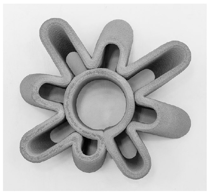
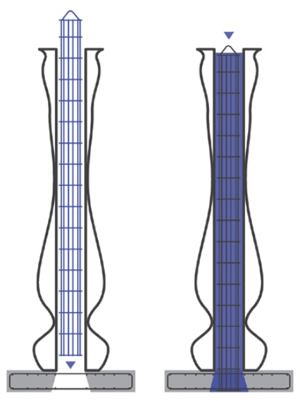
In a study conducted by Anton et al.[12] 12 columns were designed over five weeks, with a 75% success rate, and nine were sent for final installation at the site. Each column was designed with a double shell and internal bracing (Figure 3). This internal reinforcement structurally supported the adjacent layers of freshly printed material and created a mold for inserting a vertical rebar cage into the hollow cavity (Figure 4). Fresh concrete was poured into this core, and the columns were ready for transport within 24 hours [12].

For the study by Anton et al. [12], this was the most efficient method for reinforcing the printed columns. However, the reinforcement process must be re-evaluated if other geometric forms and structural elements are involved. This becomes a significant limitation due to the lack of standardized processes, and the way reinforcement is inserted can interfere with the final mechanical properties of the part. In addition, it is still a manual and not fully automated process.
Regarding the behavior of 3D-printed beams with passive reinforcement, the study conducted by Gebhard et al. [13] found no influence of printing patterns on the occurrence of cracks during flexural testing, as shown in Figure 5. Furthermore, using passive reinforcement as reinforcement for 3D-printed elements presents challenges related to porosity, as the layered manufacturing process includes voids in the component, affecting durability by creating paths for chemicals that could accelerate corrosion problems in the reinforcement. Another relevant point is that the reinforcement can compromise the geometric flexibility of the element due to the difficulty of adapting straight and rigid rebar to a specific and complex shape, and the integration of steel into 3D-printed concrete structures is still not technologically advanced [11], [14].

Another critical factor is comparing the 3D-printed beam with reinforcement and a conventional concrete structure to verify its feasibility. Through theoretical analyses, as shown in studies by Liu et al. [15], it was possible to observe that beams reinforced under tension with cementitious composite materials exhibited better deformation capacity than reinforced concrete beams of equivalent strength. Before failure, the printed beams behaved as if they had a flat section. As shown in Figure 6, the researchers concluded that cracking in these 3D-printed reinforced beams is dominated by cracks in the mid-span (bending deformation) and ends with tensile failure or adhesive failure between the printed layer interfaces [15].

Composite beam cracking pattern with an application of 3D printed cementitious composite material [15].
Zhang et al. [16] studied reinforced concrete beams manufactured using a 3D printer with manually placed tensile reinforcement compared to cast beams. Regarding strength, the study indicated that 3D-printed beams might have load-bearing capacity close to cast beams conventionally, but it also highlighted the need for more systematic studies. As for failure modes, conventionally cast beams exhibited brittle shear failure due to a lack of shear reinforcement, while 3D-printed beams exhibited bending cracks, characterized as tensile failure, as indicated by the crack pattern shown in Figure 7.

The previously mentioned studies did not evaluate the influence of printing direction on the behavior of 3D-printed elements. Moreover, preliminary studies indicate that 3D-printed beams exhibit more significant deformations and lower mechanical strength than conventional materials [16]. These findings demand more comprehensive and systematic research to explore the behavior of 3D-printed beams.
3 METHODOLOGY
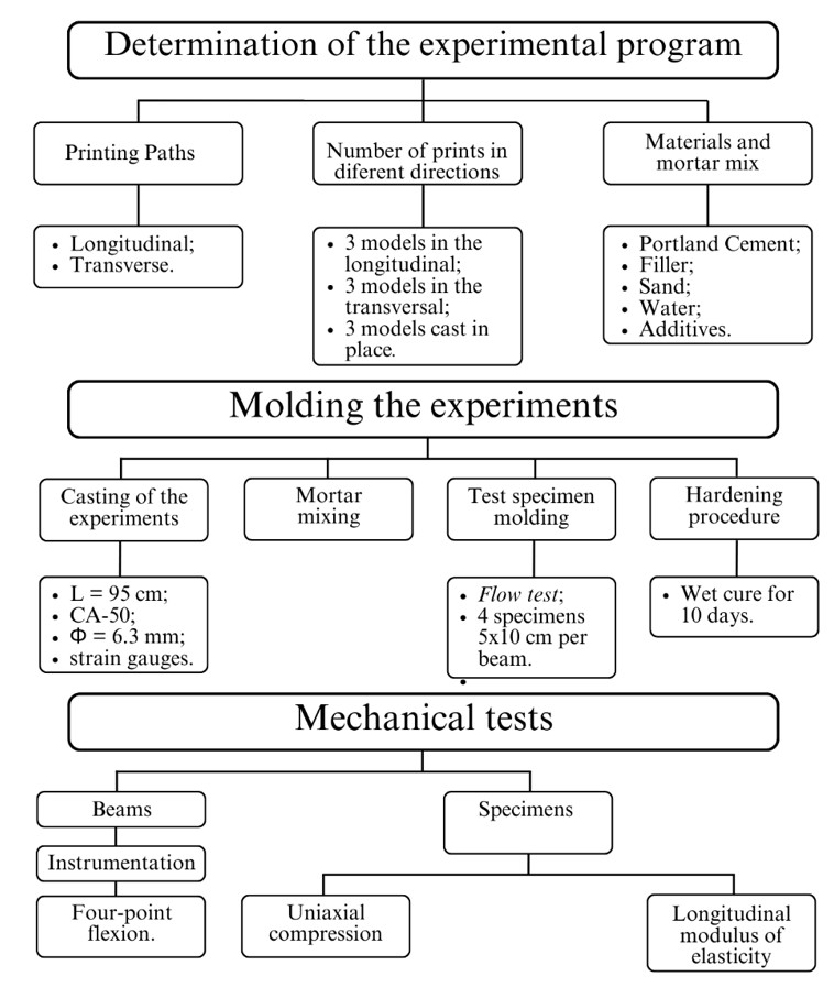
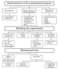
Two types of beams were printed: three beams with longitudinal printing and three with transverse printing, which will be compared with three beams cast in wooden formworks. The printing path of the beams proposed in this study can be seen in Figure 8, and the methodology applied in this study is divided into three parts and concisely demonstrated in Figure 9. The beams were printed with a cross-sectional area of 10 cm in width, 20 cm in height, and 100 cm in length.

3.1 Specification of materials
The printing mortar comprised Portland cement (CP III-32 RS, Votoran), filler derived from ornamental stone residue from the city Cachoeiro do Itapemirim, washed sand from the river Piranga - MG, water, and additives. The proportions of these materials were adopted for all experimental models, following the mix ratio of 1:1.21:2.21 (cement: filler: sand) with a water/fines ratio of 0.43, as proposed by Drumond et al. [17]. For each printed element, the following material quantities were used: 10 kg of cement, 12.1 kg of filler, 22.1 kg of sand, 9.5 liters of water, 50 g of a consistency-modifying additive, and 5 g of a plasticizer and air-entraining additive.
3.2 Material characterization
Chemical analysis by X-ray fluorescence (XRF) revealed the cement's oxide composition: 62.5% CaO, 20.1% SiO2, 5.3% Al2O3, and 3.2% Fe2O3, consistent with NBR 16697 [18]
The CP III-32 RS (Votoran) cement had a specific gravity of 2.92 g/cm3 (NBR 16605:2017 [19]), specific surface area of 464.41 m2/kg (NBR 16372:2015 [20]), and soundness of 1.0 mm (NBR 16697). Its slow setting time (initial: 120 min) was measured per NBR 16697, which aligns with its low heat of hydration but challenges early buildability in 3D printing.
The filler, sourced from Cachoeiro do Itapemirim, exhibited 85.4% SiO2 and 8.2% CaCO3, confirming its inert behavior. The sand had a fineness modulus of 1.76 (NBR NM248:2003 [21]) and water absorption of 0.91% (NBR 16916:2021 [22]).
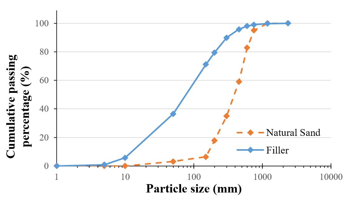
The ornamental stone filler, processed by ball milling for 30 minutes, showed a specific gravity of 2.65 g/cm3 and surface area of 744.79 m2/kg (NBR 16372:2015 [20]). Laser granulometry (Figure 10) confirmed a D50 of 20 µm, suitable for void filling. Its high silica content (85.4% SiO2 via XRF) ensures chemical stability in the mortar matrix.

Grain size distribution of sand (orange dashed line) and filler (blue solid line), highlighting the filler's fine particles (D90 < 50 µm).
Two additives were used: a consistency modifier (Cetrament Stabi 520 from MC Bauchemie) and a plasticizer and air-entraining additive (TEC MIX from GPC). Concerning the moisture condition of the fine aggregate, it was air-dried and stored in an environment protected from direct sunlight for one week.
3.3 Printing parameters
The experimental models were printed using a 3D printer from the Civil Engineering Department at the Federal University of Viçosa. The maximum printing area of the 3D printer is 650 mm x 1800 mm x 480 mm. The mortar extrusion is carried out by a screw that pushes the material through a circular nozzle with a diameter of 25 mm. The printing speed adopted was 40 mm/s, and the height defined for each layer was 12.5 mm.
Two free, open-source software programs were used for slicing and controlling the printing process: Slic3r and Pronterface. Slic3r is a slicer, a software that converts the virtual object into commands to be followed by the printer. Pronterface is a command software that takes the instructions and sends them directly to the printer's controller hardware, which manages the movements and extrudes the mortar.
3.4 Preparation of the reinforcement steel
Steel reinforcements were inserted into all the beams to ensure tensile strength. For this, two steel bars made of CA-50 steel with a diameter of 6.3 mm and a length of 95 cm were prepared for each beam. These were positioned longitudinally, ensuring a minimum cover of 25 mm as recommended by ABNT NBR 6118:2023 [23]. The beams do not have transverse reinforcement due to the difficulty of positioning such reinforcements during printing.
For each beam, one steel bar was instrumented at the center span with PA-06-125-BA-120-L strain gauges from the brand Excel Sensors. Figure 11 presents a schematic of the reinforcement positioning in the beams to be fabricated.
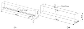
(a) Geometric properties and positioning of beam reinforcement. (b) Positioning of the extensometer to measure the deformation of the compressed concrete.
3.5 Fabrication of beams
Using a portable mortar mixer, the dry materials were added to a container, always following the same order of sand-cement-filler. For better homogenization, these dry materials were mixed for two minutes, one at a slow speed and the other at a fast speed. Then, the additives and water were gradually added, and the mortar was mixed for more 5 minutes at a fast speed.
The beams were printed horizontally (Figure 12), so the lateral face measuring 100 cm x 20 cm rested on the printing table. This method facilitated the positioning of the reinforcement bars, manually inserted after printing the 2nd and 6th layers, ensuring a 25 mm concrete cover based on the layer thickness.
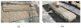
(a) Printing of the 3D beam with longitudinal (b) and transversal printing direction, with insertion of the instrumented bar.
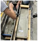
The cast beams were formed in wooden molds, with the face measuring 100 cm x 20 cm resting on the base. To ensure the minimum concrete cover for the reinforcement, 25 mm spacers were used. The mortar was compacted manually utilizing a steel bar (Figure 13).
At the end of each printing or molding process, a flow test was conducted to determine the consistency index of the concrete by ABNT NBR 13276 [19]; this test was used as a parameter to verify the consistency of the concrete during printing. Four mortar test specimens with dimensions of 5 cm x 10 cm were cast for each beam, following the recommendations provided by ABNT NBR 7215 [24], to determine the concrete's strength at the moment of the beam's failure.
3.6 Curing procedures
The beams and test specimens were stored fresh without direct sunlight exposure. These elements were moistened and covered with plastic sheeting for 10 days. After this wet curing period, the experimental models remained protected under the plastic sheeting for an additional 18 ± 1 days, totaling 28 ± 1 day.
3.7 Mechanical tests
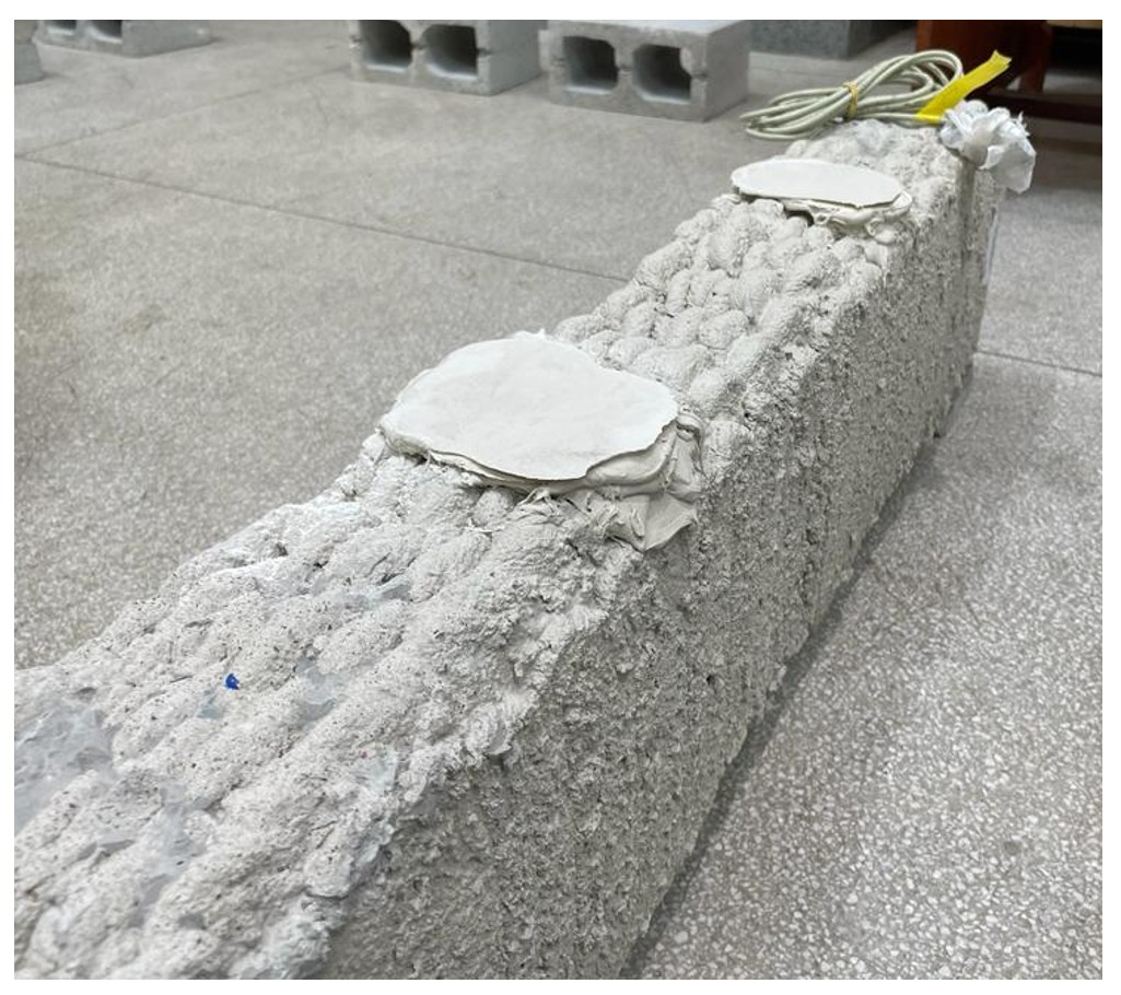
A four-point bending test was conducted to verify the beam's flexural behavior. To ensure a flat, parallel surface without stress concentration, a leveling layer was applied using putty at the points where the reaction beam rollers were supported, and where the load was applied, as shown in Figure 14.

During the flexural test, deflection was measured with a displacement transducer (DT) with a 100 mm stroke positioned vertically at the mid-span of the beam. The displacement was measured via an angle bar attached to the side of the beam, as shown in Figures 15 and 16.
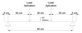
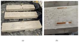
Load application distances and deflection measurement. (a) General view of the shaped beams; (b) Enlarged view.
The central positioning is strategic since the maximum deflection typically occurs at the mid-span of beams subjected to uniformly distributed or centrally concentrated loads. This displacement transducer is rigidly attached to both the support structure and the beam's bottom surface, ensuring that any vertical movement of the beam is directly transmitted to the sensor.
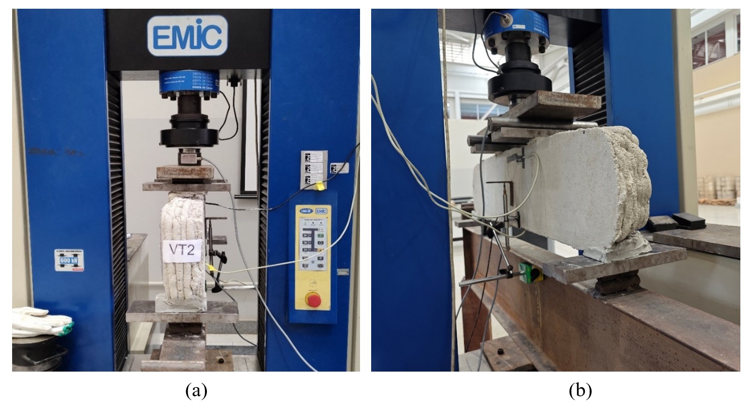
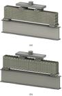
The load was applied using a universal testing machine EMIC DL-60000 (Figure 17). The load measurement was performed through a load cell connected to the machine, another load cell connected to the HBM QuantumX data acquisition system, and the strain gauges attached to the reinforcement, compressed concrete (Figure 18), and DTs.

Cylindrical specimens measuring 10 cm x 5 cm were subjected to uniaxial compression tests for mortar characterization [25] and determination of the modulus of elasticity [26].
4 RESULTS AND DISCUSSIONS
4.1 Theoretical sizing
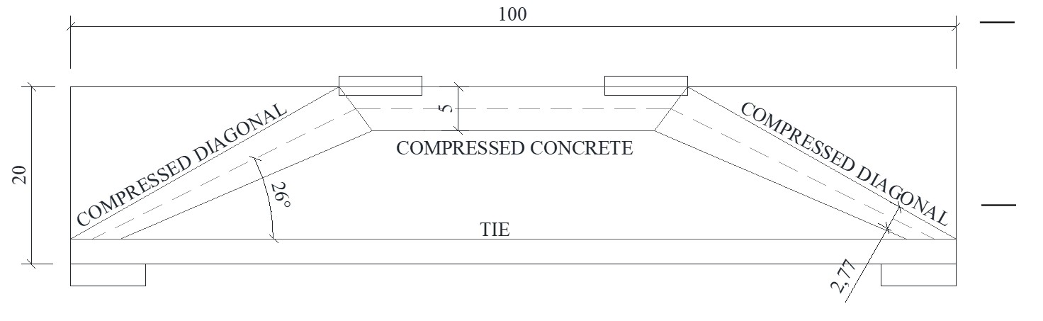
The beams were designed to correlate the theoretical values with the results from the four-point bending test. According to ABNT NBR 6118:2023 [27], performing a structural analysis of an element in the ultimate limit state is permissible using an idealized isostatic truss model consisting of struts, ties, and nodes. This methodology was employed to determine the resistance loads of the beams under study. Since these are beams with a small span-to-effective-height ratio, the stresses in the beam are highly disturbed, and thus, the strut-and-tie model better represents the behavior than the classical beam theory.
The adopted design model followed the scheme in Figure 19, where the compression was verified by considering a compressed concrete area of 40.0 cm2, with 10.0 cm being the width of the beam and 25% of the section height, resulting in a 4.0 cm height. The tensile tie, which has a cross-sectional area of 0.624 cm2 of the steel used, was also verified. Finally, the diagonal strut was analyzed, and from the adopted scheme, a diagonal width of 2.77 cm and a beam width of 10.0 cm were considered, resulting in 27.7 cm2.

Using the structural scheme from Figure 15, the strut-and-tie methodology, and an average fcm of 20.3 MPa (average value obtained from the cylinders test), the failure load of the beams was calculated as 29.11 kN.
In addition to the design using the strut-and-tie method, verification was also carried out using the classical theory of reinforced concrete beams, following the recommendations of NBR 6118 [28], yielding a load of 34.05 kN, a value higher than that obtained through the strut-and-tie methodology.
It is important to note that the design was carried out without considering any loss of strength due to the beams being 3D-printed or the direction of printing, allowing the influence of these factors on the final strength of the beams to be observed.
4.2 Processing of data obtained
The printing direction of a 3D-printed element can not only affect the element's strength but also influence the printing time and the deformations caused by the movement of the printer and the pressure from the extruder when layering.
The printing time is impacted during direction changes, as the printer must decelerate and then accelerate again to shift its movement direction. Consequently, the transversely printed beams had more segments and, therefore, more direction changes, requiring more time to complete an entire layer.
The deformations caused by the extrusion nozzle created a spreading effect on the material, resulting in an increase in section dimensions in the printing direction. As shown in Table 1, the printed beams exhibited dimensions more extensive than the programmed ones, specifically in the printing directions, which altered the inertia of the cross-section and the load capacity. For the beam nomenclature, "VM" represents the cast beams, "VL" represents the longitudinally printed beams, and "VT" represents the transversely printed beams, with the numbering from 1 to 3 representing each of the three beams for each casting method.
Due to the observed differences in cross-section, the maximum load obtained in the experimental test was corrected based on the actual inertia of the element, whether cast or printed. The loads obtained in the experimental tests were proportionally reduced according to the increase in inertia relative to the original dimensions of the element, as presented in Table 2.
4.3 Comparative analysis
The graphs in Figures 20 and 21 show the load-deformation behavior of the beams. All beams from the same group (longitudinally printed, transversely printed, and cast) exhibited similar behavior at different stages: an initial phase with stiffness gain in an uncracked state (Stage 1), which was almost linear, followed by crack formation and reduced stiffness (Stage 2), until reaching a maximum load point and, ultimately, failure (Stage 3). Additionally, in Figure 20, arrows indicate the points corresponding to steel reinforcement slippage, as the bars lacked hooks at their ends.


The results shown in Figure 20 and Table 3 reveal that, in most beams, the design was conservative, with the beams performing better than expected. Longitudinally printed beams showed superior structural behavior compared to transversely printed beams. This aligns with Section 1.1, where the anisotropic behavior of 3D-printed concrete was discussed, mechanical properties vary according to the printing direction, and in general, lower values are observed when loads are applied perpendicular to the printing direction [1], [7], [10]. Additionally, it is understood that the layering of transverse-printed beams aids in crack formation, as it introduces a weaker link in the structure, particularly in the direction that typically aligns with the crack opening pattern.
Comparatively, the printing direction was a significant factor influencing the strength of the printed beams. It was expected that the transversely printed beams would exhibit lower reinforcement adhesion, which affects their strength. Moreover, longitudinal printing proved to be faster than transverse printing. The printing nozzle gained more speed when following the longitudinal path, slowing down only during the direction changes of the mortar rows, which occurred more frequently in the transverse direction. This process caused the mortar to begin setting before fully printing the entire layer.
In the same scenario regarding the printing direction, the extruder nozzle rises by the height of a layer to proceed with printing the upper layer. The nozzle usually drags material from the lower layer along the printing path. This dragging effect was more pronounced in the transversely printed beams than in the longitudinal ones due to the higher number of sharp turns over a sh,1ort distance. As a result, print quality was compromised.
Cast beams displayed a longer elastic phase and also exhibited greater deflections and higher average maximum loads than the printed beams. This behavior is attributed to manual compaction, resulting in better bonding between the materials than the printed beams. The printed beams, being arranged in layers, did not benefit from the uniformity between layers that manual compaction provides.
4.4 Theoretical sizing applied with data obtained in the test
To evaluate the structural performance of the beams, the strut-and-tie method according to ABNT NBR 6118:2023 [28] was recalculated, this time using data obtained from the tested beams. This procedure was carried out for each beam, considering the neutral axis height determined from the strain data of the reinforcement and compressed concrete, the actual dimensions of the beams (Table 1), and the average compressive strength (fcm) obtained for each specimen (Table 4).
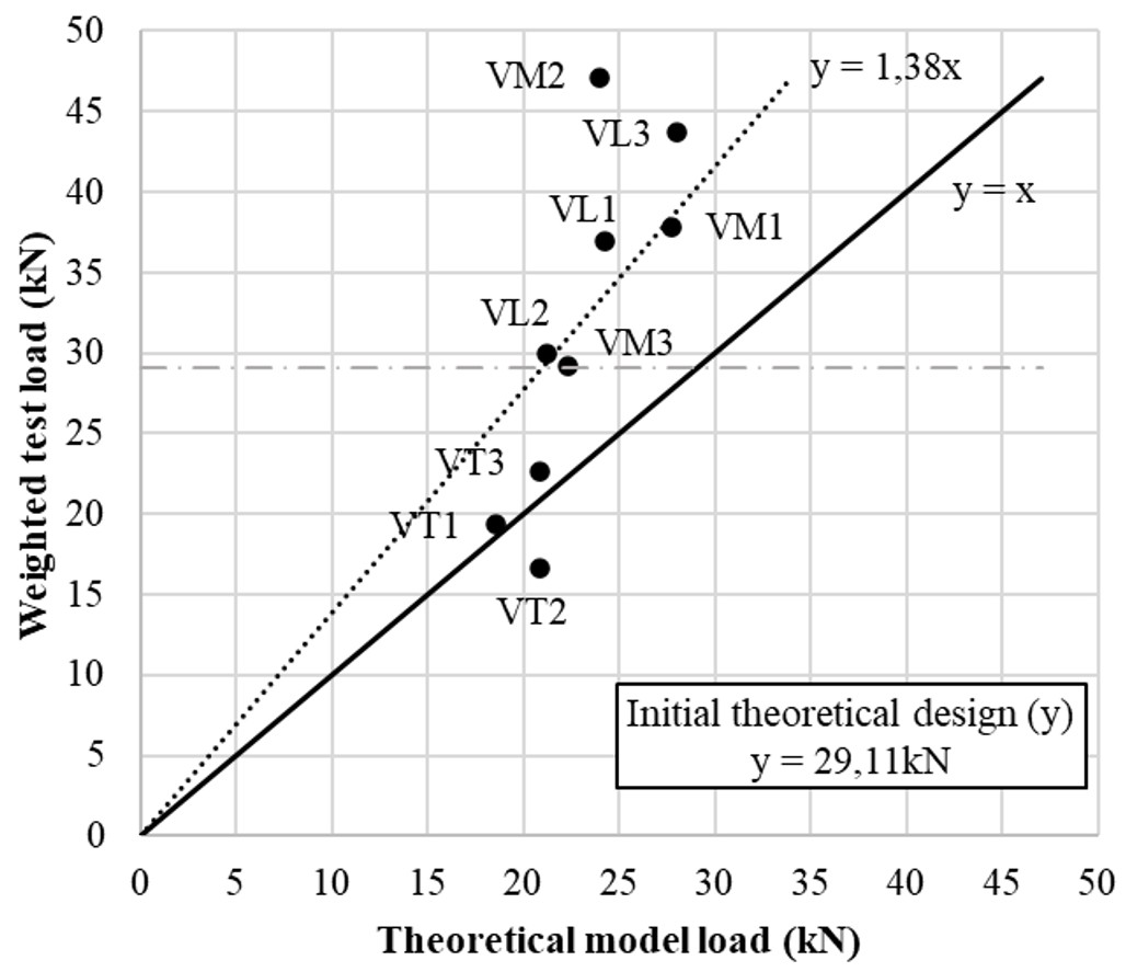
After redesigning, the calculated loads were adjusted based on the moment of inertia of each beam, similar to the adjustments made for the experimental load values. These results were compared with those of an ideal 10 cm x20 cm section. The values obtained are presented in Table 4 and the graph in Figure 18. The graph correlates the values obtained from the design model (on the x-axis) with those obtained from the experimental test (on the y-axis).
The horizontal gray dashed line represents the 29.11 kN value obtained in the initial theoretical design. In contrast, the black dashed line represents the trendline between the theoretical design values (based on the test data) and the experimental loads. The solid black line, plotted for comparison purposes, indicates a 1:1 relationship between the axes.
Table 4 and Figure 18 show that the transversely printed beams (VT1, VT2, and VT3) did not achieve the designed resistance when considering the initial theoretical design. However, based on the theoretical design with experimental data, only VT2 failed to reach the calculated strength. All other beams met the expected resistance. When comparing longitudinally and transversely printed beams, there was an evident influence of printing patterns on beam strength under flexural loads. As discussed in Section 3.3, the longitudinally printed beams approached the strength of the cast beams, whereas the transversely printed beams did not exhibit the same behavior.
Additionally, from Figure 22 and the trendline representing the beams' behavior, it was possible to infer that the beams reached 38% more resistance than the calculated design when considering all nine beams. However, this value may not represent their safety for transversely printed beams due to their lower strength. Therefore, a potential avenue for discussion is using weighting coefficients that account for the printing direction relative to the applied load direction.

The results of this experiment with 3D-printed beams both support and expand upon previous findings regarding the anisotropic behavior of 3D-printed concrete. Consistent with observations made by researchers such as Gebhard et al. [13] and Liu et al. [15], the beams exhibited initial stiffness, followed by crack formation and a subsequent decrease in stiffness, leading to failure. As also noted by [1], [9] and [11], the longitudinally printed beams demonstrated better structural performance than the transversely printed ones, highlighting the significant influence of the printing direction on mechanical strength and load capacity. This behavior reflects the anisotropy mentioned by [29], where "cold joints" between printed layers create voids that compromise structural integrity when loads are applied perpendicular to the printing direction.
Furthermore, the results indicate that while the cast beams exhibited greater initial stiffness and higher average maximum load, the quality of manual compaction could be a decisive factor in their superior performance compared to printed beams, which lack uniformity between layers. This observation aligns with the findings of Liu et al. [15], who emphasized the prevalence of mid-span cracking and adhesive failure between printed layers. The need to consider specific weighting factors for the printing direction is evident, particularly for transversely printed beams that did not achieve the theoretically designed resistance. These data underscore the complexity of the mechanical behavior of 3D-printed beams and emphasize the importance of optimizing printing strategies and compaction methods to enhance structural strength and durability.
4.5 Failure modes
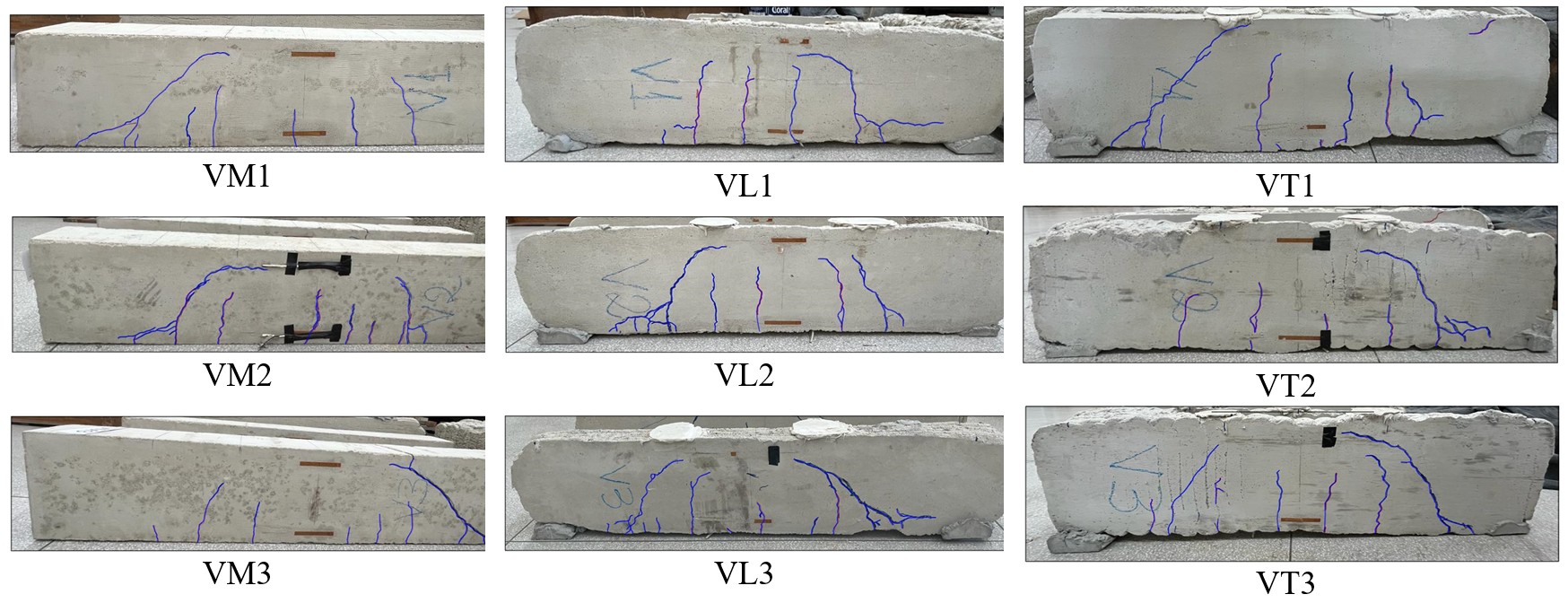
The failure behavior can be better observed by analyzing the results presented in Figure 22. There was a process of interlocking between the concrete and the ribs of the reinforcement, which can be seen at points represented by deformation peaks in both the concrete and steel, coinciding with a drop in deflection readings. With each "peak" of slippage, the concrete settled into a new rib, allowing for renewed stiffness in the structure until another slippage occurred or the beam ultimately failed.
Initially, this slippage of the reinforcement led to some early cracks. Later, the compressed struts cracked, with the cracks generated by slippage opening. The beams failed due to flexural-shear forces. The crack pattern of the beams is shown in Figure 23.

5 CONCLUSIONS
The study investigated the influence of the print direction in 3D printing of beams reinforced longitudinally under tension and compared the strength results with conventionally cast beams. Based on the study, the following conclusions were drawn:
-
Beams printed with transverse layers tend to be less resistant, as the applied loads are perpendicular to the print direction, creating a preferential path for crack formation.
-
Cast beams exhibited the highest load-bearing capacity. However, beams printed longitudinally showed similar behavior, with strengths approaching those of the cast beams. This demonstrates the potential for using printed elements for structural purposes.
-
Failures were predominantly flexural-shear, with reinforcement slippage accelerating crack initiation., which promoted cracking in the compressed diagonal struts and ultimately caused beam failure. This slippage could have been prevented by adding anchorage hooks to the reinforcement.
-
Both conventional and longitudinally printed beams achieved higher strengths than the theoretical design predicted. However, beams printed transversely presented safety concerns, as they did not reach the expected strength.
-
The strength variation with print direction underscores the necessity for future research to establish strength reduction factors based on the print direction relative to the applied load direction.
ACKNOWLEDGEMENTS
The authors would like to thank CAPES for supporting the researchers with scholarships and UFV for its partnership throughout this work.
-
Financial support:
Coordenação de Aperfeiçoamento de Pessoal de Nível Superior – CAPES. Laboratório de Estruturas – Departamento de Engenharia Civil - Universidade Federal de Viçosa.
-
Data Availability:
The data that support the findings of this study are available from the corresponding author, P. H. C. Drumond, upon reasonable request.
-
How to cite:
P. H. C. Drumond et al., “Assessment of printing direction in flexural tests of 3D printed reinforced concrete beams,“ Rev. IBRACON Estrut. Mater., vol. 18, no. 4, e18401, 2025, https://doi.org/10.1590/S1983-41952025000400001
REFERENCES
-
1 R. Robayo-Salazar, R. Mejía de Gutiérrez, M. A. Villaquirán-Caicedo, and S. Delvasto Arjona, "3D printing with cementitious materials: challenges and opportunities for the construction sector," Autom. Construct., vol. 146, pp. 104693, Feb 2023, http://doi.org/10.1016/j.autcon.2022.104693
» http://doi.org/10.1016/j.autcon.2022.104693 - 2 C. V. E. Formiga and M. L. Carneiro, "Impressão 3D para construção civil: revisão da literatura e desafios," Rev. Eng. Tecnol., vol. 13, no. 4, 2021.
-
3 H. Kloft, M. Empelmann, N. Hack, E. Herrmann, and D. Lowke, "Reinforcement strategies for 3D‐concrete‐printing," Civ. Eng. Des., vol. 2, no. 4, pp. 131–139, Aug 2020, http://doi.org/10.1002/cend.202000022
» http://doi.org/10.1002/cend.202000022 -
4 V. N. Nerella, S. Hempel, and V. Mechtcherine, "Effects of layer-interface properties on mechanical performance of concrete elements produced by extrusion-based 3D-printing," Constr. Build. Mater., vol. 205, pp. 586–601, Apr 2019, http://doi.org/10.1016/j.conbuildmat.2019.01.235
» http://doi.org/10.1016/j.conbuildmat.2019.01.235 -
5 R. A. Buswell, W. R. Leal de Silva, S. Z. Jones, and J. Dirrenberger, "3D printing using concrete extrusion: a roadmap for research," Cement Concr. Res., vol. 112, pp. 37–49, Oct 2018., http://doi.org/10.1016/j.cemconres.2018.05.006
» http://doi.org/10.1016/j.cemconres.2018.05.006 -
6 A. R. Arunothayan, B. Nematollahi, R. Ranade, S. H. Bong, and J. Sanjayan, "Development of 3D-printable ultra-high performance fiber-reinforced concrete for digital construction," Constr. Build. Mater., vol. 257, pp. 119546, Oct 2020, http://doi.org/10.1016/j.conbuildmat.2020.119546
» http://doi.org/10.1016/j.conbuildmat.2020.119546 -
7 D. H. Murcia, M. Genedy, and M. M. R. Taha, "Examining the significance of infill printing pattern on the anisotropy of 3D printed concrete," Constr. Build. Mater., vol. 262, pp. 120559, Nov 2020, http://doi.org/10.1016/j.conbuildmat.2020.120559
» http://doi.org/10.1016/j.conbuildmat.2020.120559 -
8 D. Heras Murcia, M. Genedy, and M. M. M. Reda Taha, "Examining the significance of infill printing pattern on the anisotropy of 3D printed concrete," Constr. Build. Mater., vol. 262, pp. 120559, Nov 2020, http://doi.org/10.1016/j.conbuildmat.2020.120559
» http://doi.org/10.1016/j.conbuildmat.2020.120559 -
9 J. Ye, C. Cui, J. Yu, K. Yu, and J. Xiao, "Fresh and anisotropic-mechanical properties of 3D printable ultra-high ductile concrete with crumb rubber," Compos., Part B Eng., vol. 211, pp. 108639, Apr 2021, http://doi.org/10.1016/j.compositesb.2021.108639
» http://doi.org/10.1016/j.compositesb.2021.108639 -
10 T. T. Le et al., "Hardened properties of high-performance printing concrete," Cement Concr. Res., vol. 42, no. 3, pp. 558–566, Mar 2012, http://doi.org/10.1016/j.cemconres.2011.12.003
» http://doi.org/10.1016/j.cemconres.2011.12.003 -
11 D. Asprone, F. Auricchio, C. Menna, and V. Mercuri, "3D printing of reinforced concrete elements: technology and design approach," Constr. Build. Mater., vol. 165, pp. 218–231, Mar 2018, http://doi.org/10.1016/j.conbuildmat.2018.01.018
» http://doi.org/10.1016/j.conbuildmat.2018.01.018 - 12 A. Anton et al., “Concrete choreography,“ in Fabricate 2020: Making Resilient Architecture, J. Burry, J. Sabin, B. Sheil, and M. Skavara, London, UCL Press, 2020, pp. 286–293.
-
13 L. Gebhard, J. Mata-Falcón, A. Anton, B. Dillenburger, and W. Kaufmann, "Structural behaviour of 3D printed concrete beams with various reinforcement strategies," Eng. Struct., vol. 240, pp. 112380, Aug 2021, http://doi.org/10.1016/j.engstruct.2021.112380
» http://doi.org/10.1016/j.engstruct.2021.112380 -
14 C. Schroefl, V. N. Nerella, and V. Mechtcherine, “Capillary water intake by 3D-Printed concrete visualised and quantified by neutron radiography,“in First RILEM Int. Conf. Concr. Dig. Fabrication – Dig. Concr. 2018, T. Wangler and R. J. Flatt, Eds., RILEM Bookseries, vol. 19, Dordrecht, Netherlands: Springer, 2019, pp. 217–224. http://doi.org/10.1007/978-3-319-99519-9_20
» http://doi.org/10.1007/978-3-319-99519-9_20 -
15 H. Liu, J. Xiao, and T. Ding, "Flexural performance of 3D-printed composite beams with ECC and recycled fine aggregate concrete: Experimental and numerical analysis," Eng. Struct., vol. 283, pp. 115865, May 2023, http://doi.org/10.1016/j.engstruct.2023.115865
» http://doi.org/10.1016/j.engstruct.2023.115865 - 16 S. Zhang, M. Kalus, S. Engel, J. Hegger, and M. Claßen, “Development of an Innovative 3D-Printing Process for Reinforced Concrete – AMoRC Method BT,“ in Int. RILEM Conf. Synergising Expertise towards Sustainability and Robustness of Cement-based Mater. and Concr. Struct., A. Jędrzejewska, F. Kanavaris, M. Azenha, F. Benboudjema and D. Schlicke, Eds., Cham: Springer Nature Switzerland, 2023, pp. 641–652.
-
17 P. Drumond, D. Oliveira, V. Lima, D. Veloso, and M. Charles, “Utilização de resíduo de rocha ornamental como filler em argamassa para impressão 3D,” in Anais do 6° Congr. Sul-Americano de Resíduos Sólidos e Sustentabilidade, 2023, pp. 1–10. http://doi.org/10.55449/conresol.6.23.VII-016
» http://doi.org/10.55449/conresol.6.23.VII-016 - 18 Associação Brasileira de Normas Técnicas, Cimento Portland - Requisitos, NBR16697, 2018.
- 19 Associação Brasileira de Normas Técnicas, Cimento Portland e outros materiais em pó — Determinação da massa específica, NBR 16605, 2017.
- 20 Associação Brasileira de Normas Técnicas, Cimento Portland e outros materiais em pó - Determinação da finura pelo método de permeabilidade ao ar (método de Blaine), NBR16372, 2015.
- 21 Associação Brasileira de Normas Técnicas, Agregados - Determinação da composição granulométrica, NBR NM248, 2003.
- 22 Associação Brasileira de Normas Técnicas, Agregado miúdo - Determinação da densidade e da absorção de água, NBR 16916:2021, 2021.
- 23 Associação Brasileira de Normas Técnicas, Projeto de estruturas de concreto — Procedimento, NBR 6118, 2014.
- 24 Associação Brasileira de Normas Técnicas, Cimento Portland - Determinação da resistência à compressão, NBR 7215, 1996.
- 25 Associação Brasileira de Normas Técnicas, Concreto - Ensaio de compressão de corpos de prova cilíndricos, NBR 5739, 2018.
- 26 Associação Brasileira de Normas Técnicas, Concreto endurecido - Determinação dos módulos de elasticidade e de deformação - Parte 1: Módulos estáticos à compressão, NBR 8522-1, 2021.
- 27 Associação Brasileira de Normas Técnicas, ABNT NBR Projeto de estruturas de concreto-Procedimento Design of concrete structures-Procedure, NBR 6118:2023, 2023.
- 28 Associação Brasileira de Normas Técnicas, ABNT NBR Projeto de estruturas de concreto-Procedimento Design of concrete structures-Procedure, NBR 6118, 2014.
-
29 Z. Pan, D. Si, J. Tao, and J. Xiao, "Compressive behavior of 3D printed concrete with different printing paths and concrete ages," Case Stud. Constr. Mater., vol. 18, pp. e01949, Jul 2023, http://doi.org/10.1016/j.cscm.2023.e01949
» http://doi.org/10.1016/j.cscm.2023.e01949
Edited by
-
Editors:
Rebecca Gravina, Daniel Cardoso.
The data that support the findings of this study are available from the corresponding author, P. H. C. Drumond, upon reasonable request.