 Design and experimental analysis of a steel-concrete connection with steel block shear connectors
Abstract
Abstract Hybrid structures require efficient connections to transfer forces between elements composed of different materials, ensuring the desired structural performance. Among the available solutions, shear connectors play a crucial role in linking dissimilar materials, motivating ongoing research and the development of innovative connector types. This study focuses on steel block shear connectors (SBSC), inspired by a recent demand during the design of the ARENA-MRV stadium structure in Belo Horizonte. Notably, the application of SBSC in beam-to-column connections remains unexplored in the existing literature, prompting this investigation. The research aims to develop and evaluate the structural behavior of a steel-concrete composite connection using SBSC, based on pull-out tests. The paper presents the design and details of the experimental setup, as well as a comprehensive analysis of the test results.
Keywords:
composite structures; beam-to-column connections; hybrid structures
Resumo
Resumo Em estruturas híbridas é necessário utilizar ligações que permitam transferir esforços entre os elementos formados por diferentes materiais, de forma a permitir obter o comportamento estrutural desejado. Conectores de cisalhamento são uma das principais formas de conectar diferentes materiais, motivando a pesquisa e o desenvolvimento de diferentes tipologias de conectores. Este projeto teve sua origem numa demanda recente, no contexto da concepção das soluções de projeto para a estrutura do estádio ARENA-MRV, em Belo Horizonte, onde são utilizados conectores de cisalhamento tipo bloco (SBSC). A utilização deste tipo de conector em ligações viga-pilar não foi estudada em trabalhos anteriores, motivando assim o desenvolvimento deste trabalho. O objetivo deste trabalho é desenvolver e avaliar o comportamento estrutural de uma conexão mista de aço e concreto utilizando conectores do tipo bloco, por meio de ensaios pull-out, sendo apresentados os projetos e os resultados dos experimentos.
Palavras-chave:
estruturas mistas; ligações viga-pilar; estruturas híbridas
1 INTRODUCTION
One of the challenges in hybrid structures is the connection between structural elements made of different materials. In addition to the materials being different, there are situations where a type of connection that ensures force transfer between the elements is required. In some cases, it may be desirable to achieve a composite behavior between the materials. Under the assumption of composite behavior, when steel and concrete elements act as a single unit, it is necessary to use appropriate shear connectors that enable the connection while ensuring the desired structural behavior.
In this context, over the past decades, several studies have been conducted on shear connectors to achieve composite behavior [1]–[9], as well as on the connection of different elements in hybrid structures, addressing both the development and characterization of new connection typologies. An important focus of these studies is the connection between beams and columns made of different materials. Numerous studies have been carried out on beam-column connections in hybrid structures, both internationally [10]–[19] and nationally [20]–[23].
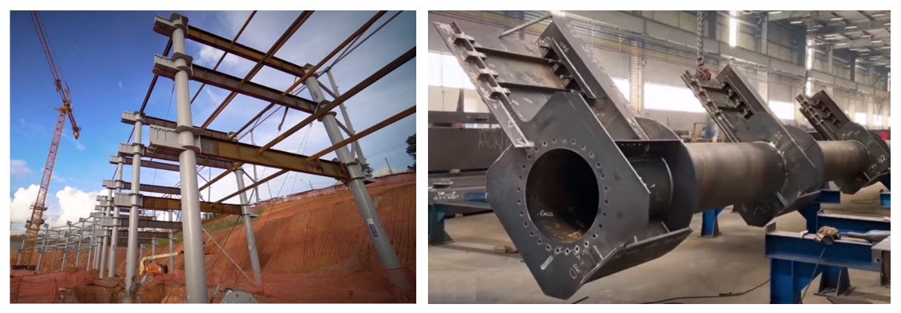
This study originated from a demand that arose in the context of designing structural solutions for the ARENA-MRV stadium in Belo Horizonte. The dimensions of the structural elements and the proposed structural arrangement, in which the precast concrete beams are connected to the concrete-filled tubular composite columns (Figure 1), required the study of the steel-concrete composite connection using steel block shear connectors (SBSC), which is the subject of this research.

Different types of shear connectors for composite structures can be classified as rigid or flexible, according to the force-slip relationship of the connection and the distribution of shear flow along the connection length. Rigid shear connectors, in addition to having high stiffness, generally exhibit significant shear resistance capacity, withstanding high forces with relatively small deformations. Such connectors are commonly used in structures with regions subject to high shear forces. In these situations, opting for flexible connectors could require the use of a large number of connectors, whose arrangement might prove unfeasible. In this case, the use of a rigid connector may be more advantageous [25]. Some studies on rigid shear connectors are presented in [25]–[29]. As for flexible connectors, a literature review on composite dowels can be found in [30].
Despite the presented context, the use of SBSC connectors in beam-column connections has not been studied in previous works, thus motivating the development of this research. The main objective of this study is the development and characterization of a rigid shear connector for composite beam-column connections in hybrid structures through an experimental analysis based on pull-out tests.
2 MATERIALS AND EXPERIMENTAL PROGRAM
To evaluate the structural behavior of a steel-concrete composite connection using steel block shear connectors, pull-out tests were conducted with two full-scale experimental models. The designs of these experiments are presented in the following sections.
2.1 Specimen characteristics
Figure 2 shows diagrams with the dimensions of the proposed specimen. It can be seen that the connectors, arranged in 3 rows, have dimensions of 50×50×60 mm. The concrete block has two lateral extensions lowered for the installation of the hydraulic actuators. This geometric arrangement was designed to prevent the overlap of compression struts, which are formed due to the spreading of compression stresses from the base of the actuators, with the tensile stresses in the region around the crosshead. Figure 3 and Figure 4 provide a detailed view of the reinforcement designed for the concrete block.

2.2 Experiment setup
Figure 5 shows a diagram of the experiment setup. The hydraulic actuators, supported on the concrete block, apply upward force, aiming to pull out the crosshead with the connectors. For safety, two lateral braces were provided for lateral stabilization of the reaction frame beam, as shown in Figure 6. To allow free vertical displacement of the beam, the columns were detached from the base, while the lateral braces remained fixed to the bases, with the bolts free to move vertically within the oblong holes.
2.3 Instrumentation and force application system
To evaluate the structural behavior of the connection, the total applied force, the relative slip between the crosshead and the concrete block, and the deformations in some reinforcement elements were measured. With this data, it is possible to determine the force-slip curve of the connection, and the deformations in the reinforcement bars serve as a record of the development of stresses within the block, which can later be used as reference to eventually develop and calibrate a numerical model, as well as allowing for monitoring the stresses in the reinforcement during the execution of the experiment.
Figure 7 shows a diagram of the designed hydraulic circuit, with two TCLRG 2006 double-acting actuators, each with a capacity of 2000 kN, connected to an ENERPAC P-464 pump. Two ENERPAC A66 manifolds were used, one for the oil inlet and the other for the oil outlet, allowing the insertion of two actuators in the same hydraulic circuit. This setup guarantees that the pressure in both actuators is the same.

Considering that the magnitude of the applied force would be very large, it was decided to measure the force indirectly from the oil pressure read by a pressure transducer installed at the inlet of each actuator, as shown in Figure 7. The data acquisition system was programmed to convert the pressure into force in real time, allowing for the monitoring and recording of the applied force values.
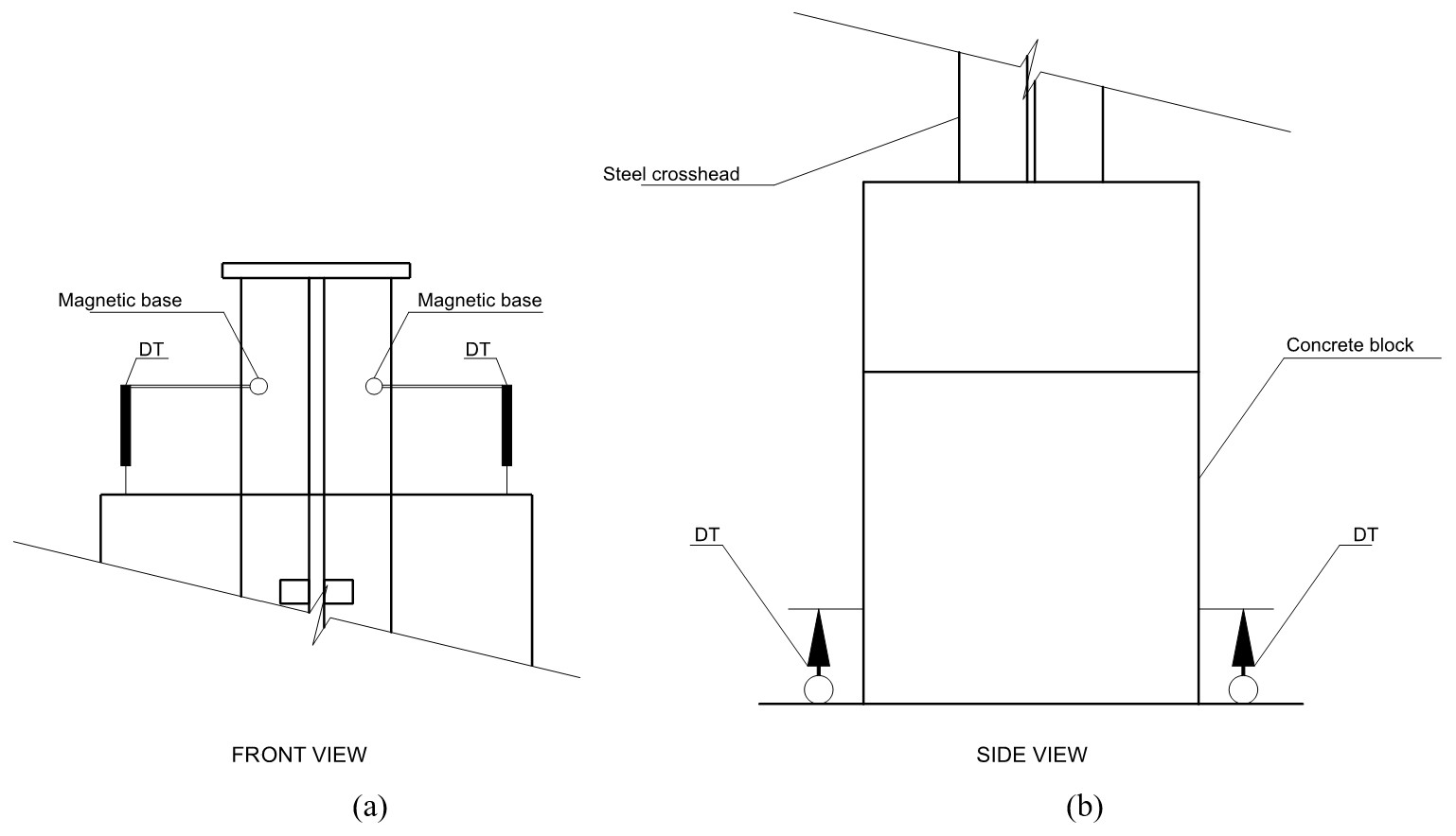
To measure the relative slip between the steel crosshead and the concrete block, two displacement transducers (DT) were installed on the steel crosshead using magnetic bases, with the rod in contact with the concrete block, as shown in Figure 8a. This configuration was adopted to enable redundancy in the measurement and to obtain the average displacement along the crosshead axis. To monitor any potential movement of the concrete block relative to the support surface, two DTs were installed near the base of the block, as shown in Figure 8b.

Positioning of the DTs: (a) for measuring the relative slip between the steel crosshead and the concrete block; (b) for monitoring the uplift of the concrete block's base.
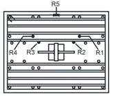
To measure the deformations in some reinforcement elements of the concrete block, strain gauges were installed on five bars, as indicated in the diagram presented in Figure 9.
4 RESULTS AND DISCUSSIONS
This section presents the results of the concrete quality control and the tests of the two pull-out test models. The models were named as Block A and Block B after the removal of the formwork, with the latter being tested first, followed by its counterpart.
4.1 Concrete quality control
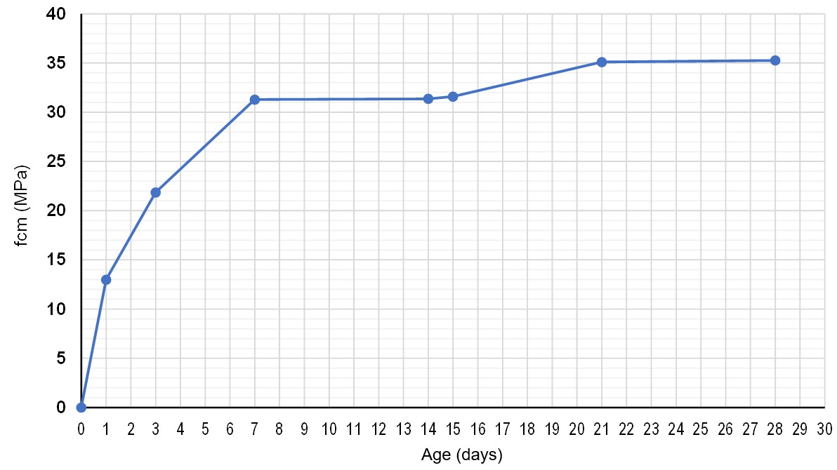
During the concreting of the blocks, cylindrical specimens were extracted for concrete quality control. The specimens were stored next to the blocks, under air curing conditions. Na Figure 10 presents a graph showing the evolution of the average compressive strength of the concrete, fcm, measured according to ABNT NBR5739:2018 [31]. Tests were conducted at the ages of 1, 3, 7, 14, 21, and 28 days, along with a measurement at 15 days, on the day of the first specimen test.
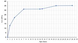
It can be observed that the concrete strength increased significantly up to 7 days, followed by stabilization until 14 days. At 21 days, an increase of approximately 10% was observed compared to the value obtained at 14 days, followed by another stabilization until 28 days. This phenomenon was expected, as the cement used was of the CPV ARI type, which develops most of its strength in the early ages, followed by a slowdown in strength growth in the subsequent ages.
For the Specimen B test, at 15 days, the measured average compressive strength of the concrete, fcm, was 31.6 MPa. In turn, for Specimen A, tested at 23 days, the value of 35.1 MPa, measured at 21 days, was considered.
4.2 Specimen B test
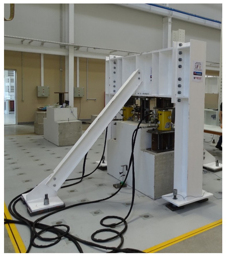
The first specimen tested in the laboratory was the so-called Specimen B. Na Figure 11 shows an image of the experiment setup. The block was directly supported on the reaction slab, with the steel crosshead bolted to the reaction frame beam. The hydraulic actuators were positioned on steel brackets so that their activation moves the frame upward, thereby causing the pull-out of the steel crosshead relative to the concrete block.

In the Specimen B test, two displacement transducers were used to measure the relative slip between the steel crosshead and the concrete block, as shown in Figure 12. Therefore, for each displacement sensor, one force-slip curve was obtained.

Displacement transducers installed in Specimen B to measure the relative slip between the concrete block and the steel crosshead.
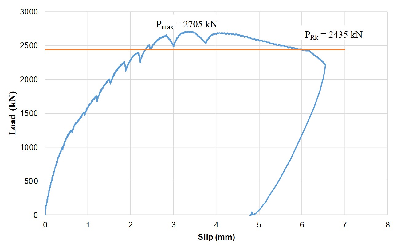
Figure 13 presents the force/slip curve corresponding to the average slip obtained from the two displacement transducers. It can be observed that the maximum force reached in the model was 2705 kN, when the model exhibited an average relative slip of 3.41 mm. According to the criterion presented in [32], the characteristic force, PRk, is equal to 90% of the maximum force value, thus being 2435 kN for Specimen B. The relative slip, δu, is taken as the corresponding slip to the characteristic force of the model, being equal to 6.0 mm in this case. Finally, the characteristic relative slip, δuk, is determined by multiplying δu by 0.9. Thus, a δuk of 5.4 mm is obtained for Specimen B.

The post-peak behavior of the connection is also noteworthy, with a gradual decrease in force after reaching the maximum load point. The ability of the connection to retain part of its load-bearing capacity after the peak demonstrates that the failure occurs in a ductile manner.
In addition to the displacement measurements used to determine the relative slip between steel and concrete, two additional displacement transducers were installed in the Specimen B test, one on each side of the block, to measure any potential uplift relative to the surface on which it was supported (Figure 14). Figure 15 presents a graph with the measurements from these transducers. It can be observed that the average displacement between the transducers reached a maximum value of approximately 0.5 mm, indicating that the concrete block did not experience a significant uplift at its base.


Figure 16 presents images of the cracking observed in Specimen B. The numbers written on the concrete block correspond to the applied force, in tf, at the moment the crack was observed. It can be noted that cracking in the block first appeared at a force of 175 tf, with the initial cracks progressing as the force increased. Additionally, the formation of new cracks was observed at a load of 225 tf.

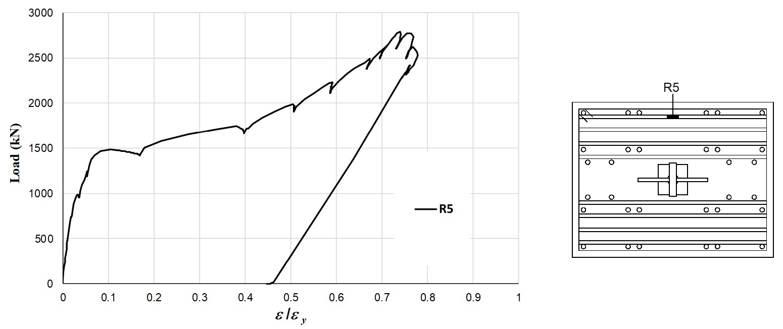
In addition to the force and displacement measurements, strain gauges were installed on some reinforcement bars of the block near the steel crosshead. Figure 17, Figure 18 and Figure 19 present graphs showing the strain evolution in the instrumented bars, expressed as a ratio relative to the yield strain (εy) of CA-50 steel.


Figure 20 shows the strain evolution in the reinforcement bars parallel to the crosshead, relative to the yield strain of CA-50 steel, at the positions of strain gauges R1, R2, R3, and R4, from left to right, respectively. It is observed that from the early stages of the loading phase, up to approximately 1500-1750 kN, the reinforcement bars were mobilized in a very similar manner. From this point onward, the measurements began to diverge. Additionally, it is important to note that the maximum strain measured did not exceed 60% of the yield strain of CA-50 steel.

4.3 Specimen A test
The second pull-out model tested in the laboratory was designated as Specimen A. Figure 21 presents an image of the experimental setup. It is noteworthy that the same setup procedure used for Specimen B was adopted for this model.

Figure 22 presents the force-slip curve corresponding to the average displacement obtained from the two displacement transducers. It is observed that the maximum force reached by the model was 2803 kN, occurring at a relative slip of 2.8 mm. The characteristic force PRk was equal to 2523 kN for Specimen A. The relative slip δu was 5.8 mm, leading to a characteristic slip δuk of 5.2 mm. As observed in Specimen B, the post-peak behavior of the connection also presents a gradual decrease in force following the peak load.

Figure 23 presents images of the cracking observed in Specimen A. The numbers marked on the block correspond to the applied force, in tf, at the moment when the crack was observed. It is noted that cracking began to appear at a force of 100 tf, with the progression of the initial cracks as the force increased. Furthermore, new cracks were observed at a load of 225 tf.

Figure 24, Figure 25 and Figure 26 present graphs showing the evolution of strains in the instrumented bars of the reinforcement, presented as a rate relative to the yield strain (εy) of CA-50 steel.


5 CONCLUSIONS
As observed in the experiments conducted, the connection designed in this study achieved an average load-bearing capacity of 2754 kN. In both tested models, a high initial stiffness was observed during the early loading stages, followed by a reduction and stabilization of stiffness up to the maximum load. In the post-peak behavior, the connection maintained its load-bearing capacity as the slip progressed, without a sudden drop in load. This indicates that the connection exhibited a ductile failure, with a gradual loss of load-bearing capacity in the post-peak phase.
Regarding the reinforcement of the concrete block, it was observed that none of the bars instrumented with strain gauges reached the yield point of CA-50 steel. The deformations in the longitudinal and transversal bars did not exceed 60% and 80% of the yield limit, respectively.
Furthermore, it is noted that the reinforcement designed for the concrete block was able to improve the concrete's behavior. Even after the onset of concrete cracking, the presence of the reinforcement allowed the resisting force to continue increasing.
The solution using rigid connectors demonstrated a high load-bearing capacity, reaching a maximum force of approximately 230 kN per connector. It is also noteworthy that the connection has a significant ability to transfer forces within a relatively small area compared to flexible connectors. The connection studied in this work had an embedment length in concrete of only 700 mm, enabling a substantial transfer of forces with a limited number of connectors.
Thus, it can be stated that the connection using steel block shear connectors (SBSC) studied in this work exhibited adequate structural behavior for use in composite joints in hybrid steel-concrete structures.
ACKNOWLEDGEMENTS
The authors wish to acknowledge the Fundação de Amparo à Pesquisa do Estado de Minas Gerais (FAPEMIG), through research project APQ02328-22, and CODEME Engenharia S.A. for their support in the realization and dissemination of this study.
-
Financial support:
Fundação de Amparo à Pesquisa do Estado de Minas Gerais (FAPEMIG), Project APQ02328-22.
-
Data Availability:
the data that support the findings of this study are available from the corresponding author, C. L. Pereira, upon reasonable request.
-
How to cite:
C. L. Pereira, G. S. Veríssimo, P. R. Parassen, and J. L. R. Paes, “Design and experimental analysis of a steel-concrete connection with steel block shear connectors,” Rev. IBRACON Estrut. Mater., vol. 18, no. 4, e18404, 2025, https://doi.org/10.1590/S1983-41952025000400004
REFERENCES
-
1 S. E. Kim and H. T. Nguyen, "Finite element modeling and analysis of a hybrid steel-PSC beam connection," Eng. Struct., vol. 32, no. 9, pp. 2557–2569, Sep 2010, http://doi.org/10.1016/j.engstruct.2010.04.029
» http://doi.org/10.1016/j.engstruct.2010.04.029 -
2 M. Classen and M. Herbrand, "Shear behaviour of composite dowels in transversely cracked concrete," Struct. Concr., vol. 16, no. 2, pp. 195–206, 2015., http://doi.org/10.1002/suco.201400100
» http://doi.org/10.1002/suco.201400100 -
3 M. H. Mollazadeh and Y. C. Wang, "New insights into the mechanism of load introduction into concrete-filled steel tubular column through shear connection," Eng. Struct., vol. 75, pp. 139–151, Sep 2014, http://doi.org/10.1016/j.engstruct.2014.06.002
» http://doi.org/10.1016/j.engstruct.2014.06.002 -
4 M. Feldmann, M. Kopp, and D. Pak, "Composite dowels as shear connectors for composite beams – background to the german technical approval," Steel Constr., vol. 9, no. 2, pp. 80–88, 2016, http://doi.org/10.1002/stco.201610020
» http://doi.org/10.1002/stco.201610020 -
5 M. Classen and J. Hegger, "Assessing the pry-out resistance of open rib shear connectors in cracked concrete – Engineering model with aggregate interlock," Eng. Struct., vol. 148, pp. 254–262, Oct 2017, http://doi.org/10.1016/j.engstruct.2017.06.050
» http://doi.org/10.1016/j.engstruct.2017.06.050 -
6 M. Kopp et al., "Composite dowels as shear connectors for composite beams – Background to the design concept for static loading," J. Construct. Steel Res., vol. 147, pp. 488–503, 2018, http://doi.org/10.1016/j.jcsr.2018.04.013
» http://doi.org/10.1016/j.jcsr.2018.04.013 -
7 M. Classen, M. Herbrand, V. Adam, D. Kueres, and M. Sarac, "Puzzle-shaped rib shear connectors subjected to combined shear and tension," J. Construct. Steel Res., vol. 145, pp. 232–243, 2018, http://doi.org/10.1016/j.jcsr.2018.02.036
» http://doi.org/10.1016/j.jcsr.2018.02.036 -
8 E. C. Oguejiofor and M. U. Hosain, "Parametric study of perfobond rib shear connectors," Can. J. Civ. Eng., vol. 21, no. 4, pp. 614–625, 1994., http://doi.org/10.1139/l94-063
» http://doi.org/10.1139/l94-063 -
9 G. Veríssimo, “Desenvolvimento de um conector de cisalhamento em chapa dentada para estruturas mistas de aço e concreto e estudo do seu comportamento,” Ph.D. thesis, Univ. Fed. Minas Gerais, Belo Horizonte, Brazil, 2007. [Online]. Available: http://hdl.handle.net/1843/LMCA-7E6HVC
» http://hdl.handle.net/1843/LMCA-7E6HVC -
10 J. G. Bouwkamp and H. W. Ashadi, “An aseismic hybrid composite structural frame system for buildings,” in Int. Symp. Earthquake Dis. Prev., México, DF, 1992, pp. 110–117. [Online]. Available: https://pesquisa.bvsalud.org/portal/resource/pt/des-3291
» https://pesquisa.bvsalud.org/portal/resource/pt/des-3291 - 11 B. Kato, M. Kimura, H. Ohta, and N. Mizutani, “Connection of beam flange to concrete-filled tubular column,” in Comp. Constr. Steel Conc. II, New York, 1992, pp. 528–538.
- 12 H. Shakir-Khalil, “Full-scale tests on composite connections,” in Comp. Constr. Steel Conc. II, New York, 1992, pp. 539–554.
- 13 H. G. L. Prion and A. B. McLellan, “Through-bolt connections for concrete-filled hollow structural steel sections,” in Proc. Annu. Task Group Tech. Ses., Bethlelem, 1994, pp. 239–250.
- 14 H. W. Ashadi and J. G. Bouwkamp, “Behaviour of hybrid composite structural earthquake resistant joints,” in 10th Eur. Conf. Earthquake Eng., Rotterdam, 1995, pp. 1619–1624.
- 15 H. Shakir-Khalil, "Experimental study of concrete-filled rectangular hollow section columns," Struct. Eng. Rev., vol. 6, no. 2, pp. 85–96, 1994.
- 16 J. S. Shims, D. J. Han, and K. S. Kim, “An experimental study on the structural behaviors of H-shaped steel beam-to-concrete filled steel tubular column connections,” in Proc. 4th Pacif. Struct. Steel Conf., 1995, pp. 41–48.
-
17 S. P. Schneider and Y. M. Alostaz, "Experimental behavior of connections to concrete-filled steel tubes," J. Construct. Steel Res., vol. 45, no. 3, pp. 321–352, 1998., http://doi.org/10.1016/S0143-974X(97)00071-0
» http://doi.org/10.1016/S0143-974X(97)00071-0 -
18 J. Beutel, D. Thambiratnam, and N. Perera, "Monotonic behaviour of composite column to beam connections," Eng. Struct., vol. 23, no. 9, pp. 1152–1161, 2001, http://doi.org/10.1016/S0141-0296(01)00002-5
» http://doi.org/10.1016/S0141-0296(01)00002-5 -
19 A.-K. Al-Rodan, "T-cleat connections to concrete-filled tubular internal columns," J. Struct. Eng., vol. 130, no. 5, pp. 725–731, 2004, http://doi.org/10.1061/(ASCE)0733-9445(2004)130:5(725)
» http://doi.org/10.1061/(ASCE)0733-9445(2004)130:5(725) -
20 S. De Nardin, “Pilares mistos preenchidos: estudo da flexo-compressão e de ligações viga-pilar,” Ph.D. thesis, Escola Eng. São Carlos, São Carlos, Brazil, 2003, http://doi.org/10.11606/T.18.2003.tde-28112003-163232
» http://doi.org/10.11606/T.18.2003.tde-28112003-163232 -
21 R. S. Farias, “Estudo teórico-experimental do efeito da laje na transferência de forças em ligações viga-pilar,” Ph.D. thesis, Escola Eng. São Carlos, São Carlos, Brazil, 2008, http://doi.org/10.11606/D.18.2008.tde-11062008-112706
» http://doi.org/10.11606/D.18.2008.tde-11062008-112706 -
22 J. L. Conceicao, “Ligação mista viga-pilar resistente a momento,” M.S. dissertation, Univ. Fed. Minas Gerais, Belo Horizonte, Brazil, 2011. [Online]. Available: http://hdl.handle.net/1843/PASA-8H5GQT
» http://hdl.handle.net/1843/PASA-8H5GQT -
23 L. M. Bezerra, “Estudo teórico-experimental da ligação entre pilares mistos preenchidos e vigas pré-moldadas de concreto,” Ph.D. thesis, Escola Eng. São Carlos, São Carlos, Brazil, 2011, http://doi.org/10.11606/T.18.2011.tde-20092011-110345
» http://doi.org/10.11606/T.18.2011.tde-20092011-110345 -
24 Arena MRV, “Peça feita para aguentar a massa” Arena MRV. https://www.youtube.com/watch?v=2peH6loi5fQ (accessed Jun. 26, 2025).
» https://www.youtube.com/watch?v=2peH6loi5fQ -
25 Y.-H. Wang, J. Yu, J. Liu, and Y. F. Chen, "Experimental and numerical analysis of steel-block shear connectors in assembled monolithic steel–concrete composite beams," J. Bridge Eng., vol. 24, no. 5, pp. 1–12, 2019, http://doi.org/10.1061/(ASCE)BE.1943-5592.0001384
» http://doi.org/10.1061/(ASCE)BE.1943-5592.0001384 - 26 W. Zhou and X. Wang, “Lattice launch test of t-type connectors-One of the researches on series of steel-concrete composite truss,” J. Hefei Univ. Technol., no. 3, pp. 84–90, 1993.
- 27 L. Wang, “Numerical calculation of steel truss and concrete composite beam and design of shear connector,” M.S. thesis, Southwest Jiaotong Univ., Chengdu, China, 1998.
-
28 M. M. Ahmadi and S. R. Mirghaderi, "Experimental studies on through-plate moment connection for beam to HSS/CFT column," J. Construct. Steel Res., vol. 161, pp. 154–170, 2019, http://doi.org/10.1016/j.jcsr.2019.06.010
» http://doi.org/10.1016/j.jcsr.2019.06.010 -
29 N. B. Eghbali and P. Andamnejad, "Structural performance of rigid shear connectors in concrete encased steel composite columns," Structures, vol. 54, no. May, pp. 348–368, 2023., http://doi.org/10.1016/j.istruc.2023.05.040
» http://doi.org/10.1016/j.istruc.2023.05.040 -
30 J. V. F. Altoé, C. S. Faria, M. C. Petrauski, C. L. Pereira, J. L. R. Paes, and G. S. Veríssimo, "Composite dowels shear connectors for steel-concrete composite beams: a review," Rev. IBRACON Estrut. Mater., vol. 18, no. 2, pp. 1–25, 2025, http://doi.org/10.1590/s1983-41952025000200004
» http://doi.org/10.1590/s1983-41952025000200004 - 31 Associação Brasileira de Normas Técnicas, Concreto – Ensaio de Compressão de Corpos de Prova Cilíndricos, NBR5739, 2018.
- 32 European Committee for Standardization (CEN), Eurocode 4 - Design of Composite Steel and Concrete Structures - Part 1-1: General Rules for Buildings, EN1994-1-1, 2004.
Edited by
-
Editors:
José Marcio Calixto, Daniel Cardoso.
the data that support the findings of this study are available from the corresponding author, C. L. Pereira, upon reasonable request.