 Space and time in special relativity
Abstract
In this review of the kinematic part of Einstein’s Theory of Special Relativity, the physical meaning of the Lorentz Transformations is elucidated from basic physical facts that, although implicit in the formulation of the theory, are usually overlooked in literature and textbooks. The consequence of the invariance of that distinguishes this theory from its classical version is the relativity of simultaneity at a distance that causes time intervals to be frame dependent, space and time being otherwise completely equivalent in different inertial frames. Lorentz Transformations are derived from a graphical representation of the axes of a pair of inertial frames that preserves their equivalence, implied by the Principle of Relativity. Transformations of space and time intervals are analyzed from a perspective wider than the usual. The problems related to the derivation of the time dilation formula using light-clocks and the twin paradox are treated in detail.
Keywords:
Special relativity; Lorentz transformations; length contraction; time dilation; twin paradox
1. Introduction
The purpose of this article is to evidentiate the simplicity and self-consistency of the kinematic part of Einstein’s Special Theory of Relativity (STR) [1]. The difficulty that students have to understand it does not arise from the theory itself, but from the fact that, very frequently in literature and textbooks, some of its basic consequences are overlooked, in favor of misinterpretations.
To explain the last statement, consider two inertial frames in the usual configuration: frame A, in relation to which frame B moves with a constant velocity along a direction we call in both frames. As for any mathematical relation among physical quantities, to relate the space and time coordinates of events as observed1 from A and B requires establishing common scales (or units) for measuring intervals of position and time in both frames. The SI units metre and second (or multiples of them) are used in practice. By doing so, we are assuming that the metre represents the same distance and the second represents the same duration in any inertial frame. That this is so is very clear from the current definition of the SI [2] based on fundamental physical constants – the speed of light in vacuum, , being one of them – which renders SI units as physical constants.2 This is an essential consequence of the Principle of Relativity which applies to any properly defined scales for distance and duration. It is acknowledged in traditional books on relativity [3, 4, 5] but almost implicitly and, in my view, is not properly emphasized. In some other texts it is completely overlooked.
On the other hand, the invariance of the speed of light in vacuum leads to the relativity of simultaneity at a distance. Two simultaneous events separated along the direction in frame B, so that , are not simultaneous in frame A, which means . Therefore, the time coordinates and are not synchronized with each other, which causes the elapsed time between two events to depend on the frame from which they are observed. The space counterpart of this is the trivial effect of the relative motion of the frames, which makes position intervals frame dependent as well. The Lorentz transformations (LT) result from both effects applied to finite intervals taking into account the Principle of Relativity.
In summary, the equivalence of inertial frames implied by the Principle of Relativity encompasses the quantitative meanings of distances and durations. On the other hand, the values of the position and time coordinate intervals of a given pair of events differ along the direction of the relative motion of two frames as given by the LT [3, 4, 5]. For the frames A and B, they may be written as:
with the usual abreviation
The factor arises naturally in any derivation of the LT. It’s not a “scale factor” between units of measurements in different frames: if so, due to the isotropy of space in inertial frames, it should be present in equations (1c) and (1d) as well. The inverse relations may be obtained by solving the pair of equations (1a) and (1b) for and . This results in relations completely similar to the original ones with the labels A and B interchanged and a minus sign before , which is consistent with the fact that the velocity of A relative to B is . That happens only for as given in equation (1e) and we see that this factor has the role of making the Lorentz transformations proper physical laws according to the Principle of Relativity.
The well-known results of STR called length contraction and time dilation result from particular applications of the LT and do not involve any differences in length or time scales between frames. Despite this, literature and textbooks sometimes present careless descriptions of these results which cause confusion and give rise to paradoxes. Time dilation and the associated retardation of moving clocks are explained as due to the slowing down of time itself in moving frames (see, for instance, chapter 15 in vol. I of the Feynman Lectures on Physics [6]). As the previous arguments have shown, and will be further discussed in the article, this is a misinterpretation of the phenomenon, and of STR itself.
In this article, a review of the kinematic part of STR as developed by Einstein is given, stressing its consequences that are commonly overlooked or misinterpreted in literature and textbooks. It includes a graphical derivation of the LT and detailed analyses of transformations of space and time intervals. The problems related to the misinterpretation of the time dilation formula from its derivation using light-clocks and the twin paradox involve all the important aspects of the theory and, for this reason, are treated in detail.
2. The Principles of Special Relativity
STR, as formulated by Einstein, is based on two quantitative principles. The first, called Principle of Relativity, states that the physical laws are the same in any inertial frame of reference. The second states that in all inertial frames, the speed of light in vacuum has the same constant value which is independent of the state of motion of its source. For short, this will be referred to in this article as the “invariance of ”.
An inertial frame of reference is one in which the law of inertia is valid: any material body free of external forces maintains its state of rectilinear uniform motion. The isotropy and translation symmetry of the physical space described by such a frame derives from this law, which must be valid irrespective of the direction of the constant velocity and of the location of the trajectory of the free body. A constant velocity means that a given distance is traversed in the same interval of time regardless of its location along the rectilinear trajectory of the free body. Therefore, time “flows” equally and uniformly, and does not depend on position.
It is clear that, restricted to a given inertial reference frame, these properties of space and time are no different from their classical versions. Kinematics, the description of motion, is identical in STR and in classical mechanics. The laws that govern the motion of material bodies, however, are not the same: the laws of Newtonian Mechanics, except for the first, do not conform with the principles of STR and were reformulated by Einstein.
To describe the locations and instants of time in a reference frame quantitatively it is convenient to establish a system of coordinates. The isotropic physical space with Euclidean geometry is conveniently described by a Cartesian system of coordinates, based on three mutually perpendicular directions , and ; parallel to each of them are defined the corresponding axes issuing from a common origin. Any orientation of the set of three mutually perpendicular directions and corresponding axes in physical space can be used and the choice is based on convenience for the problem at hand. To a particular location in physical space are, then, assigned three values for the independent coordinates, , and .
Inherent to this procedure is the use of a unique standard for distance to quantify the three coordinates. Let be such unit of distance, defined by the length of particular physical devices such as identical measuring rulers at rest. Mathematically, we express the value of the position coordinates as
Here, , and are real numbers (of the mathematical set ) called the numerical values of , and in the unit .
The time coordinate is independent of the space coordinates and is expressed as , where is any particular standard, defined through the duration of the cycle of a specified clock. Here, also, , but the fourth in the set of independent coordinates has physical properties that distinguish it from the other three: differently from the space directions, the sense of the time-axis cannot be inverted due to the principle of causality (a cause must precede its effect) or the second law of Thermodynamics (entropy can only increase in time). To properly assign experimental values of , clocks are positioned at rest throughout the physical space. These clocks may be of any kind that works in the absence of gravity, and must be calibrated to give readings of in the same unit . They must also be synchronized so that the time indicated simultaneously by each of them is the overall time of the frame.
An experimental observation of a physical process in a frame A is performed, in principle, as follows3. An observer will be situated close to each of these clocks, monitoring it and its immediate vicinity. The space and time coordinates for a given event are assigned by the observer situated at the event’s location, from his own position, and the clock reading . As the process evolves, a series of events is observed and recorded by different observers until its completion. The result of the observation comprises the ensemble of these measurements. All this is important to perform actual experiments and, here, to settle the ideas. What a physical theory does is to predict the outcome of possible experiments, which are calculated employing the appropriate physical laws.
To address the relations among coordinates in different inertial frames consider two frames of which frame B moves relative to frame A with constant speed along the common direction. Then, frame A moves relative to B with constant speed in the opposite direction . The other orthogonal directions, and , are also taken to be the same in frames A and B. A given event will be characterized by particular values of the four coordinates in frame A and in frame B.
Consider two points and fixed on a -plane in frame B so that and . As the points move perpendicular to the -axis their coordinates are independent of time in either frame and by symmetry . This equality must be true also for points fixed in frame A. An inequality in this relations would imply an asymmetry between motions in and directions, a violation of the isotropy of space, and of the Principle of Relativity as well. The same result applies, evidently, for any direction transverse to , and therefore the transformations of the related position intervals are simple equalities:
In frame A or B the directions , and , have no special meaning because space is isotropic (they have been singled out for convenience by something alien to the frame, namely, the direction in which the other frame moves). Therefore, any given distance has the same quantitative meaning in whatever direction not only in A and B, but in any inertial reference frame. In other words, as already stated in the introduction, one metre represents the same distance along any direction in any inertial frame.
The position coordinates along the direction of the relative motion, on the other hand, are frame dependent and their relations depend on the relative velocity of the frames. The speed of frame B relative to frame A, , is related to the time it takes for a point fixed in frame B to travel a given distance parallel to the direction in frame A by ; conversely, considering a point fixed in frame A and the same given distance in the direction, . These two time intervals must be equal, , because, as space is isotropic, there’s no way to decide which one is longer. Thus, time “flows at the same rate” in any inertial frame or, in other words one second (or any given time interval) represents the same duration in any inertial frame, as stated before. Notice that the invariance of just corroborates this conclusion, since the elapsed time for light to travel a given distance in any direction is the same in any frame. Consequently ,4 and the relative velocities are such that . Hence a point fixed in frame B is described by
and a point fixed in A by
The symmetry dictated by the law of inertia and the Principle of Relativity imply that any inertial frame is equivalent to any other regarding distances and durations. This conclusion seems “natural” in classical terms, but it is worth emphasizing that it applies both to classical relativity and to STR. That does not imply that the intervals of space and time coordinates of two events are the same. To figure out the relation between generic values of the coordinate pairs and further information is needed. Classical, or Galilean, relativity is based on the Newtonian paradigm of absolute time, independent of frames, and assumes that for any pair of events. The invariance of , on the other hand, implies that this is not so.
Consider a possible experimental procedure for the synchronization of two clocks positioned at rest in two points and along the -axis of a given frame. Their midpoint is determined, and from it two rays of light are emitted at the same time along the directions and in vacuum. Both clocks will be reached simultaneously by the rays; this simultaneity can be used to synchronize their readings.5 In frame A the two points are moving with velocity and symmetrically positioned at a distance from . As both rays move with the same speed , clearly, the point that moves toward the emission point will be reached before the point that moves away from it. Taking at and at the moment of the emission and , the encounters of the rays with the two points are, respectively,
Adding the two equations and using the first equality of each of them results
The result for points at rest in frame A as observed in B is obtained just by changing the sign of . In both cases the moving point that is behind is reached before the point ahead. This quantitative statement of the relativity of simultaneity can be expressed as6
In words, any two simultaneous events in a given frame are not simultaneous in any other frame that moves along their spatial separation. This means that the time coordinates of the two frames are not synchronized between each other. Consequently, clocks that work synchronously in one frame are not observed to do so from any other frame moving parallel to their spatial separation. This consequence of the invariance of reveals a remarkable difference between classical time and its STR counterpart. Formally, however, the only difference between the time coordinates of frame A and of frame B is an asynchrony proportional to space separation along the direction of the relative motion. Every kinematic phenomenon of STR can be derived from the combination of the effects described by (equations 3) and (4), which render both spatial and temporal intervals between any pair of events to be frame-dependent.
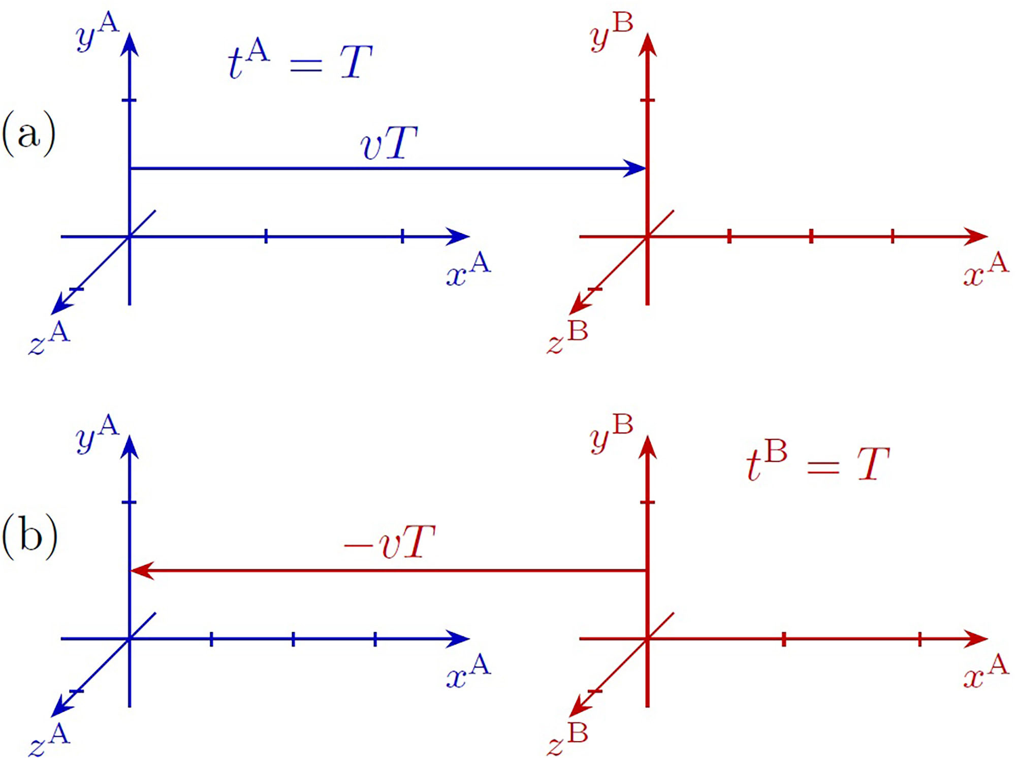
The relativity of simultaneity poses a problem when one draws the sketches of two reference frames in relative motion. The situation is represented in Figure 1. In (a), the axes of frame A are taken to be stationary and a snapshot of the axes of frame B, which moves at velocity , with , is sketched for a fixed value of . The separations of the unit marks along the five axes , , , and are all equal. However, the separations along are different from those of because any plane of frame B at a given corresponds to a different value of . Each mark along is drawn for a time that is earlier than the time for the preceding one, so that marks are closer than the marks. In (b), B is taken to be stationary and A is the moving frame. Actually, the -marks for the moving frame cannot be drawn before the theory is developed.

Conventional representation of two inertial reference frames with relative speed . The scale marks of the -axes of the moving frames were drawn taking into account the relativity of simultaneity for . (a) Taking frame A as the stationary one, the sketch represents both frames at a fixed value . (b) Frame B is stationary and the axes are drawn for a fixed value .
2.1. Other consequences of the principleof relativity
This section addresses the quantitative nature of the Principle of Relativity and its consequences.
The laws of classical electromagnetism are valid quantitatively in any inertial frame. These laws comprise the Lorentz force, ), which defines the electric and magnetic fields, and Maxwell’s equations that state the mathematical relations among them and with their sources. It is implicit in these equations that the value of the electric charge of any particle is independent of its motion. In the usual formulation, Maxwell’s equations involve two fundamental physical constants, namely, (vacuum electric permittivity) and (vacuum magnetic permeability). They are not independent because they are related to the speed of propagation of transverse electromagnetic waves in vacuum, .
Physical constants take part in all the basic physical laws. Among them are the Planck constant , from quantum theories, and the rest masses and electric charges that characterize the components of particular physical systems. Therefore, the Principle of Relativity implies that physical laws are the same in any frame, not only in form, but also quantitatively. As basic physical laws govern natural processes of any kind – physical, chemical, biological, etc. –, this principle implies that each inertial frame is equivalent to any other regarding the laws of nature in general.
There are two perspectives associated with the Principle of Relativity. On the one hand, any natural process, or experiment, replicated under the same conditions evolves identically in any inertial frame. On the other hand, any given process is governed by the same physical laws, regardless of the frame from which it is observed. In both classical relativity and STR, this does not mean that a given process is observed in the same way from any frame: the same laws applied to the same physical system under different conditions lead to different results. The crucial difference between the two theories is that in the former time intervals do not depend on the frame, while in STR they do.
The two perspectives have been exemplified by the experiments described earlier in relation to the relativity of simultaneity. Another example, invoked by Einstein in his paper, is the electromagnetic interaction between a magnet and a conductor loop in relative motion. In the frame in which the magnet is at rest, there is only a magnetic field that, acting on the free carriers carried along by the moving conductor, induces an electric current. In the frame where the conductor is at rest, the time-varying magnetic field induces an electric field that causes the current. Fields, forces and currents are different in each case. Further examples are discussed in section 5 in relation to the phenomenon of clock retardation.
Consider a measuring ruler moved from being at rest in frame A to being at rest in frame B. In frame A, its rest length (say ) as well as any other of its physical properties,7 are determined by the laws that govern the interaction among its atomic components. Once at rest in frame B, because the same physical laws apply, its rest length will have the same value . Observed from A, where the ruler is now moving, the same laws apply but under different conditions; therefore, its length does not have to be . The same conclusion holds for any physical device, such as a particular clock used to define the unit for time, , when at rest in frame A. When moved to a state of rest in frame B, the duration of its cycle – determined by the same physical laws in identical conditions – will be the same as it was in A; therefore, represents the same duration in A, B, or any other inertial frame. Again, when observed from a frame relative to which the clock is moving, the same physical laws in different conditions will result in a duration for the cycle that is different from .
To transport a physical device from one frame to another involves acceleration. To describe in detail the process of accelerating any extended solid is no trivial matter, even in classical mechanics. Any such process will require the application, or release, of localized contact forces. For instance, a force applied to one end of a solid bar will give rise to deformations and internal tensions that propagate along the solid as acoustic waves, which are reflected at its surface causing it to vibrate in a complicated manner during the process of acceleration. In classical mechanics, a drastic approximation is made which amounts to considering the solid as a perfectly rigid body that instantly acquires the acceleration as a whole. In regular situations this is a very good approximation because the deformations are very small and the speed of sound is high compared to the speeds involved. Under STR, however, such an approximation, that implies the instantaneous transmission of the effects of the localized force, is not possible even in principle. However, it is not necessary to know the details of the process to conclude that, after the accelerating forces have ceased, the internal vibrations have died out, and the solid has acquired a constant speed, it will be at rest in another inertial frame and will have the same physical properties it had at the original frame, as long as the forces had not damaged its internal structure.8 Therefore, in principle, the setup of any inertial frame may be established by using the same standard ruler and clock providing them with a common set of units.
3. Graphical Derivation of the Lorentz Transformations
The usual graphical representations of the and axes of two inertial frames take the point of view of one of the frames, whose axes are drawn perpendicular to each other. This makes the axes of the other frame necessarily non-orthogonal and, thus, does not evidentiate the equivalence of the frames. It turns out that, just by representing both pairs of axes in an equivalent form, the relations among the coordinates, the Lorentz transformations, can be obtained from simple trigonometric relations.
It is convenient to work with the numerical values of the coordinates, which are real variables, using the same units for both frames. The units of length and time are set to obey the relation:
so that
The unit for speed is, then, , which sets the numerical value of to be . Any ray of light propagating along the direction will be described by
To fulfill the principle of the invariance of it suffices that the same graphical scale is used for space and time intervals, regardless of the angle between the axes for and . Two light-lines through the origin correspond to two perpendicular straight lines that bisect the angles between the time and position axes.
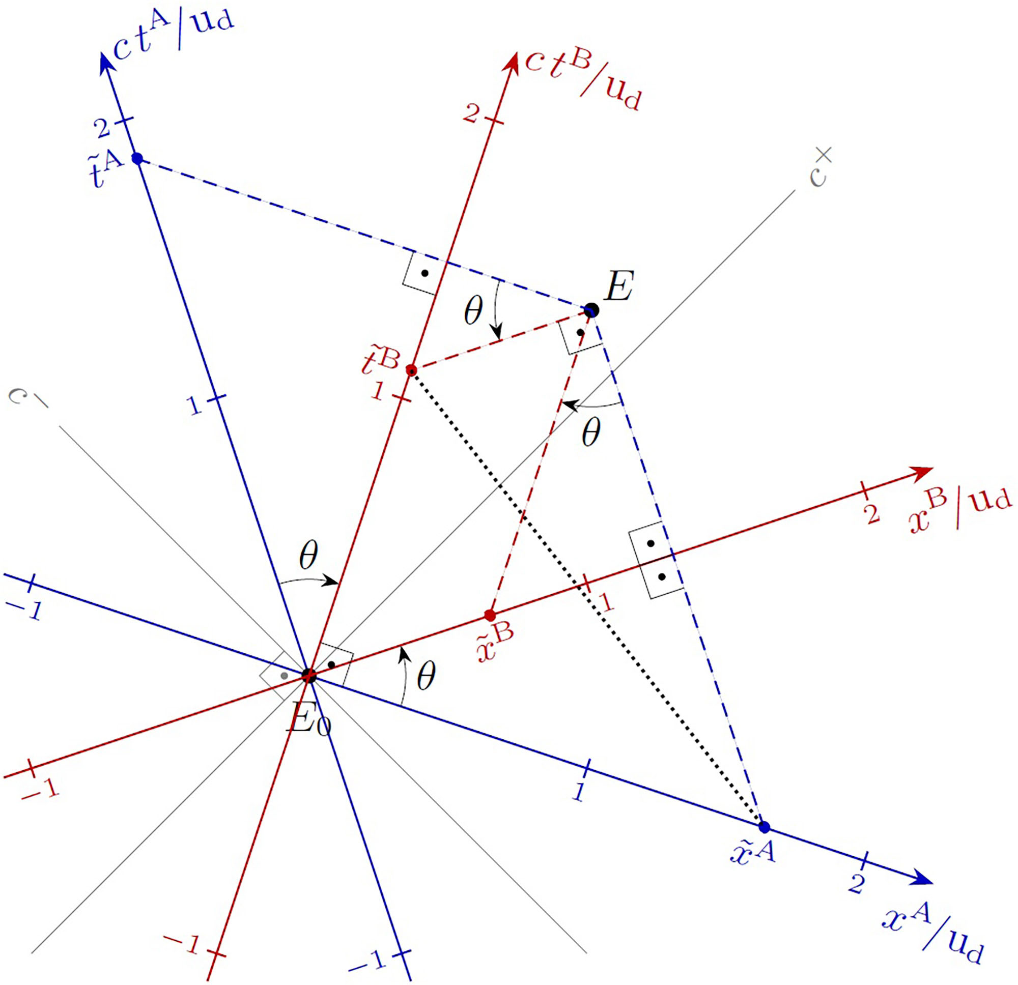
Figure 2 shows a graphical representation of the axes of two inertial frames, A (blue) and B (red), which moves with velocity relative to A, drawn from a common origin , in equivalent form. The canvas on which the picture is drawn is a representation of the real plane with Euclidean geometry. The orientation of the two perpendicular light-lines and (thin gray) was chosen to make the picture visually symmetric. The axes of A were drawn symmetrically around and those of B around . It is clear from the picture that the axes and , as well as and , are perpendicular to each other due to the orthogonality of the light-lines. The graphical scales for the axes of the two frames must be identical by the symmetry of the representation, which conforms with the fact that space and time intervals are quantitatively equivalent in both frames – specifically, one metre represents the same distance and one second represents the same duration in A, B or any other frame.

Graphical representation of the axes and of inertial frames A and B in equivalent form with .
The representation is conveniently characterized by , the angle from axis to axis which is the same from to . The physical meaning of is obtained from the geometric relations between the axes of B and A. From the two right triangles indicated in the figure between, respectively, the -axes and the -axes, it follows that
These relations, which result naturally from the graphical representation, are equivalent to equations (3a) and (4a). Therefore,
and , assumed to be positive in Figure 2, represents the velocity of B relative to A.
The relations among the coordinates of a given event in frames A and B follow from the geometry of right triangles indicated in Figure 2. They may be written in terms of the differences of the coordinates of and as:
In this form they apply to any pair of events regardless of the events chosen as the origin for each frame.
In equation (10), was taken as positive, which limits to the interval . The reason is that a negative cosine in the above equations would imply that a purely time interval in one frame would correspond to a negative time interval in the other, which is regarded as unphysical.
A graphical representation similar to that in Figure 2 can describe any pair of inertial frames, just by adjusting the angle and choosing the -direction to be parallel to their relative velocity. As , it is clearly impossible to represent frames with relative speeds greater than using real variables. Therefore, is a limiting speed for reference frames and, consequently, for any material particle.
Another important result can be obtained from the geometry of the graphical representation in Figure 2. The two right triangles with legs of lengths and issuing from , and and issuing from share a common hypothenuse (black dotted line in the figure). This gives the relation
which is equivalent to
This equality holds for the differences of the coordinates of events and in any inertial frame. That means that for any pair of events the quantity
has the same value in any inertial frame [3, 4, 5]. This well-known result shows that, despite the symmetry in which time and space intervals appear in (equations 11), time is not equivalent to space.
Substituting the numerical variables in (11) by their relations to the corresponding physical variables and the units related by (5), and using (equations 10), the LT are obtained in the usual form as already given by (equations 1).
The inverse transformations may be obtained from (11) by interchanging the labels A and B, and setting . For further reference, the non trivial part of them reads:
The constant factors before the ’s have been introduced to emphasize the symmetric roles of space and time intervals in the LT.
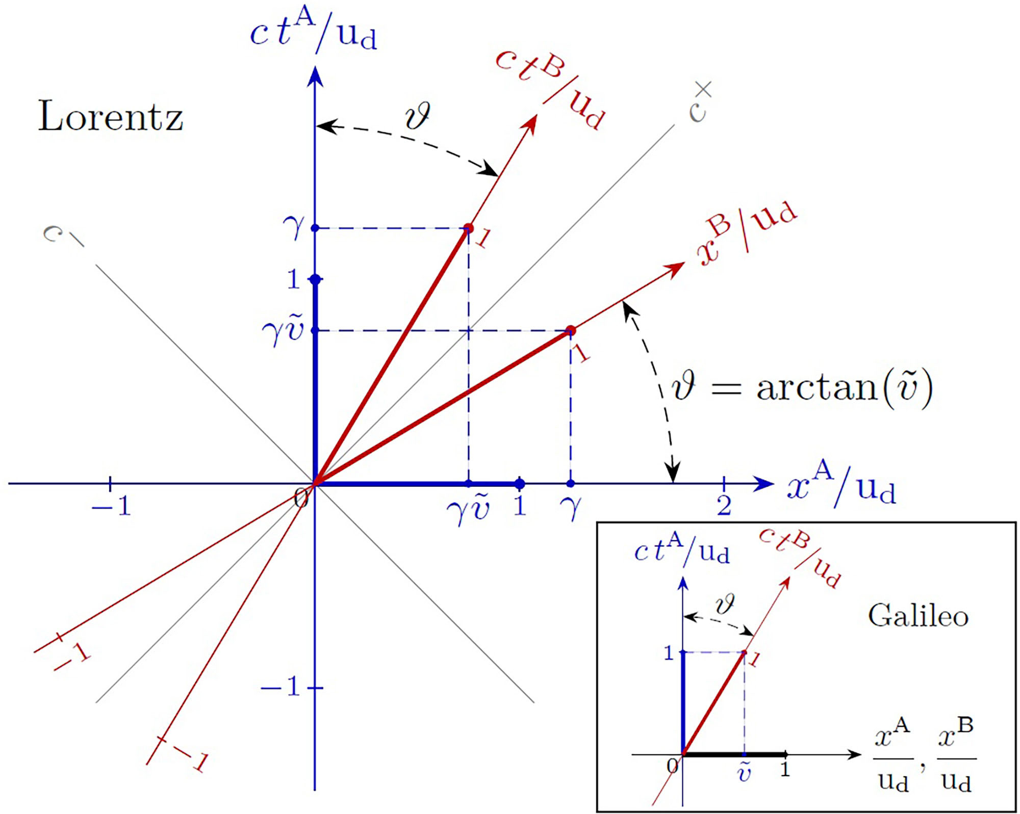
Figure 3 shows the usual graphical representation of the same reference frames of Figure 2. The axes for frame A were chosen to be at right angles to each other, and this requires those of B to be non-orthogonal. The scales for the axes of frame B were drawn after setting the scales for A and using the LT. The thick blue segments correspond to unit intervals for and , and the red ones for and . In contrast to Figure 2, the red segments are larger than the blue ones by a factor . This graphical effect results from privileging frame A in the representation, and makes it necessary to apply the given calibrating factor to compare graphical readings of time and space intervals in the two frames.9 An analogous graphical distortion, although with a different factor , results for the time scales in a similar representation of the axes of two frames under classical relativity, as shown in the inset of Figure 3.

Conventional graphical representation of two reference frames using the Lorentz Transformations. The inset ilustrates the case of Galilean relativity.
The representation of the axes of two inertial frames in Figure 2 is a visually symmetric version of a Loedel diagram. It was first introduced by Loedel in an article on the phenomenon of aberration [8] and, independently, later, by Amar [9, 10] and Brehme [11, 12]. They are seldom used in literature [13] despite the advantage that with them no scale factor is needed to compare space and time intervals in the two frames. The present article has shown that they can be set up simply by resorting to the invariance of and choosing the orientation and scales of the axes to manifest the equivalence of the two frames dictated by the Principle of Relativity. Such a diagram, therefore, can be taken as the starting point for the derivation of the LT.
4. Length Contraction and Time Dilation
In this section the transformations of space and time intervals between frames are analyzed from a perspective that clarifies the physical meaning of length contraction and time dilation. As several pairs of events will be involved in the discussion, for easier reference the following notation will be used for coordinate differences between two events labeled and :
Take two points fixed on the -axis of frame A at distance . For the sake of argument, the points may mark the ends of a solid bar at rest with its length along that axis. Since the bar is at rest in frame A, the position coordinates of its endpoints are independent of time, which is expressed by . The two fixed coordinates are represented in Figure 4 (drawn for the case ) by the -axis and the line labeled parallel to it.
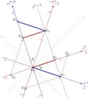
Graphical representation of length contraction and time dilation. The picture has been drawn with ().
To obtain the coordinates in frame B from those in frame A we use the inverse LT given in (13). The results to be derived here are easily seen graphically by resorting to the relations in equation (10).
For the current problem we get
and may have any value depending on .
The blue thick bar joining the events and in Figure 4 is a representation of the bar at . For this pair of events, the above equations give
as indicated, respectively, by the events and in Figure 4. The interval is characterized as a proper distance or length. The interval , which is larger than by a factor , does not represent the bar or its length in frame B, because the positions of its two endpoints have been determined at two different moments, between which it has moved. A measure of the distance between two moving points, in frame B or any other, requires their positions to be determined at the same time, both in STR and in classical relativity. To get that condition, we set in (15), which gives
The thick red line along in Figure 4 represents the moving bar at , and shows that its length is shorter in frame B than in frame A. This phenomenon is known as length contraction, distance contraction, or Lorentz contraction. On the other hand, from equations (1c) and (1d), the lateral dimensions of the bar are the same in both frames. The effect is reciprocal, as demonstrated by the relation between and , the latter being a proper distance in frame B.
This shows that Lorentz contraction is a real effect – as real as the invariance of that implies the relativity of simultaneity. As Figure 4 makes evident, the set of simultaneous events that represent the observation of the bar at a given instant in one frame, does not represent its observation in the other, and conversely. That has an objective physical meaning: the distance between any two points at rest in a given frame is, in fact, shorter along the direction of their motion in any other inertial frame that moves relative to the first, as illustrated in Figure 1. Despite the terminology used sometimes, no “space contraction” is involved; the length scales of frames A, B, and all others, remainidentical.
Suppose a particle is at rest in frame B at . In frame A, the particle moves with velocity ; therefore, the time it takes for it to travel along the bar is given by . The blue line along in Figure 4 represents the bar at the end of this time interval. In frame B, the bar – now with a contracted length – moves with velocity , and the time it takes for it to pass the particle is . The final position of the bar in frame B is represented by the red line along . Therefore,
Equation (18) is an example of the phenomenon called time dilation. It relates the time interval , between two events at the same position in frame B, called a proper time interval, with a nonproper time interval in frame A, in which the events occur in different locations. Its physical meaning is clear: is, in fact, longer, or dilated, in comparison to the proper time interval by the factor . For any given pair of frames, equation (18) applies even if the events are displaced along the lateral directions , . The definition of a proper time interval, on the other hand, implies .
The effect is reciprocal: from Figure 4,
where is a proper time interval. Although numerically, it is clear that each of the (equations 18) and (19) applies to a different pair of events, so that time dilation is reciprocal between frames, but not “symmetric”.
It’s instructive to analyse the subject of time transformations from a wider perspective. Consider that an interval of time has elapsed in frame A. Figure 5 illustrates an example in which the time intervals between any event on the -axis and another on the dashed line labeled have the same value in frame A. In this case (equations 13) give

Graphical representation of the transformations of a fixed time interval in frame A. The picture has been drawn with ().
These equations represent for a fixed duration what (equations 15) represent for a fixed distance , and, similarly, can have any value, depending on .
Setting , it follows, for instance,
as can be read, respectively, from the events and in Figure 5. The fact that, in principle, the two time coordinates are assigned from clocks at different locations in frame B is irrelevant because, being synchronized, all clocks in B indicate simultaneously the same value for . In this case, represents the dilated interval associated with the proper time interval .
By setting , which implies , we obtain, for instance:
The results (21) and (22) illustrate the reciprocity of time dilation. In the present case is a proper time interval and its associated dilated time interval.
Setting , it follows, for instance,
This indicates that events and are simultanious in frame B. For any , the value of becomes negative and the order of the events in frame B are inverted.
Suppose event is the cause of event for which, in frame A, and . For a frame moving with velocity relative to A, the LT equation (13a) gives
Considering the possibility , it follows that there would be frames with for which and the order of the events would be reversed. But the principle of causality requires that in all reference frames; thus, necessarily, . Therefore, is the limit for the relative speeds of reference frames and for the speed of any kind of massive physical object, and the maximum speed for the propagation of interactions. We see that, despite its name, is more than just the speed of light in vacuum. It is a universal constant that is present in expressions of relativistic theories, like the LT themselves, that have no relation to electromagnetic waves.
The analyses of this section demonstrated that Lorentz contraction has a meaningful physical implication: the spatial dimensions and the distances between physical objects at rest in a given frame are shortened along the direction of their motion in any other frame. On the other hand, the time dilation formula is just a particular instance of time interval transformations among inertial frames in which one of them is a proper time interval. It is worth emphasizing that it has no implication on the rates at which time passes, which is the same in all inertial frames.
The time dilation formula can be written in a general form as:
where the superscript in indicates that this is a proper time interval associated with the condition in a given frame. The interval on the right side is the corresponding dilated time interval in a different frame which moves in any direction with speed relative to the first. In this form, it applies to finite time intervals regardless of the physical process occuring between the events.
The concept of a proper time cannot be assigned to extended bodies or devices in general, nor, evidently, to reference frames. A proper time may be assigned to a particle, or a sufficiently small body, that moves with velocity in a given inertial frame [3, 4, 5]. The particle, even if accelerated, can be regarded as being momentarily at rest in an inertial frame moving with the same velocity relative to the original frame. Denoting by the differential increment of the proper time of the particle, and by the corresponding elapsed time in the inertial frame, it follows that
If the function that describes the time evolution of the speed is known, any finite proper time interval of the particle can be obtained by integrating this expression.
5. Stationary and Moving Clocks
The devices sketched in Figure 6, known as light-clocks, are commonly used to demonstrate time dilation. In simple terms, each device has two parallel mirrors, held a distance from each other. A ray of light bounces back and forth as it is consecutively reflected by the mirrors in a cyclic process, making such a device the simplest kind of clock in relativity. Not shown in the figure are the structures that keep the mirrors in place, and the vacuum chambers around the paths of the rays. In the following, the predictions of STR for two identical devices, set up perpendicular to each other as in the Michelson-Morley’s experiment, are displayed.

As indicated in Figure 7, the setup of two perpendicular devices is at rest in frame B and moves with velocity in frame A, from which it is observed. The subscripts “” and “” distinguish between the results for, respectively, the transverse and the longitudinal devices. The intervals for the travel of a ray from one mirror to the other, and back are labeled, respectively, with “” and “”. In frame B the durations of the half cycles are all the same, namely , so that

Time evolution of the positions of the rays of light for the setup of two identical light devices oriented perpendicular to each other, with equal proper distances between mirrors . The setup is at rest in frame B that moves with speed relative to frame A. In frame B: (a) transverse and (b) longitudinal devices. As observed from frame A: (c) transverse and (d) longitudinal devices. The graphical scales for both time and position coordinates are the same in all plots.
The total duration of a cycle, , is the same for both devices:
For an identical setup at rest in frame A, the durations are all the same as the durations in frame B, as follows from the Principle of Relativity and the invariance of . That is why these devices are considered as clocks in STR.
The durations observed from frame A may be obtained using the LT equation (1a), which for the parts of the cycles in B may be written as:
For the -clock, with and , it results:
For the -clock, with , we have:
and
The total durations of the cycles of both devices, as observed from frame A, are dilated by the factor in comparison with their values in the rest frame B. This is time dilation: both and are proper time intervals and and the respective dilated time intervals. For the and parts, the time intervals are nonproper, but in the particular case of the -device, the same factor applies for both because . That is not the case for any other orientation of the devices, as implied by equation (29) and exemplified in equation (32) for the -device.
From the perspective of frame A, the cycles of both devices, and consequently of all the clocks of frame B, are observed to be longer than those of their own clocks at rest by the common factor . This is known as clock retardation and is usually simply stated as “moving clocks run slower”. As it involves observations from a single reference frame, although obviously related to it, this phenomenon is not the same as time dilation. The latter applies to proper elapsed times related to physical processes of any kind, not necessarily involving clocks or cyclic processes. Clock retardation is an example of the second perspective of the Principle of Relativity discussed in section 2.1: the same physical laws applied to identical processes in different conditions give rise to different results.
Such a retardation is naturally expected for the moving light devices. For the case of the -device, as can be seen from Figure 6(b), the distance travelled by its light ray is larger than for the stationary device in (a) by the factor . In the case of the -device, assuming a distance between the mirrors, the durations of the and parts of its cycle are, respectively, and , which sum up to give for the entire cycle. As the cycles of both the and the devices start and end simultaneously at the same location, their durations must be equal to each other in any frame. For that, the distance has to be taken as , which is Lorentz contraction10. Thus, the same factor applies for the path of the ray of the longitudinal device, as implied by the LT.
The plots in Figure 7 illustrate the time evolution of the positions of the front end of the rays derived from these results. They were drawn taking , for which . Plots (a) and (b) show the results in frame B, and plots (c) and (d) in frame A. The sketch of the setup for frame A in (c) shows the distance between the mirrors of the longitudinal is Lorentz contracted. Both time dilation and relativity of simultaneity are evidenced by the comparison of the corresponding plots. From another perspective, the plots in (a) and (b) may be considered as giving the time evolution of the identical setup at rest in frame A, in which case Figure 7 illustrates clock retardation. As plot (d) in Figure 7 shows, the retardation of the -device is not uniform along the cycle; for the numerical example used, one part is four times longer than the other.
The fundamental point that must be emphasized is that STR predicts the effect of retardation of clocks in motion must be observed, not only for light-clocks for which it is expected, but for clocks of any kind (atomic, mechanical, electromagnetic, radioactive). Any physical theory, to be valid, must conform to this prediction. The details of what happens during the cycle depend on the particular machinery of the clock, but the effect on the entire cycle does not. A non-uniform behavior, similar to that described for light-clocks, has been demonstrated by Redžić [14] from the dynamical analysis of another kind of electromagnetic clock, a charged particle oscillating along the axis of a charged ring. The problem was solved for the clock at rest and in uniform motion employing relativistic mechanics and Maxwell’s electromagnetic theory. The results are consistent with the predictions of the LT given in (29), exemplifying the self-consistency of STR.
In many textbooks, of which the Feynman Lectures [6] is an example, from the retardation of the transverse device it is concluded that STR predicts a “slowing of time with motion”. The reasoning may be summarized as follows: “as the moving clocks are observed to run slower than the stationary clocks, and this should be true for any clock moving along with frame B, time itself and all phenomena are slowed down in the same proportion in frame B”. That is a misinterpretation of STR itself, as the relativistic definition of what a clock does has been overlooked. In relativity, as discussed in section 2.1, a clock measures the time coordinate of the frame in which it is at rest, and for that it is necessary to distinguish them as and just as it is done for the space coordinates. Clearly, , for instance, is supposed to be measured by clocks at rest in frame A. The moving device is a clock by itself but only in frame B, where it is at rest, and is smaller than not because it is “slow” but because, evidently, it is related to a different time coordinate, . For the case of the longitudinal device is even longer than the dilated ; for the part the relation is inverted: is smaller than and the moving clock is observed to go faster than the clocks at rest.
If the predictions of STR for the longitudinal device had been considered by the authors of basic textbooks of relativity, the contradictory misinterpretations of the phenomena of time dilation and length contraction would most probably not be so widespread. Fortunately, STR is much simpler: there is no contradiction in its prediction that observed from frame A the cycles of moving clocks of B are longer than those of the stationary ones and conversely, regardless of how this happens in detail. As the Lorentz transformations show clearly, it is not a general rule that every phenomena are observed as slowed down when taking place in a moving frame.
6. Twin Paradox
If the Lorentz transformations, the core of STR, are correctly applied to a physical problem, the result will be correct, regardless of how they were interpreted. Paradoxes arise when conclusions are drawn directly from misinterpretations, without properly solving the problem. The well known twin paradox is a good example.
One of the twins makes a round trip with speed , from Earth to planet X at a distance and back, while the other remains on Earth. Both Earth an planet X are considered to be at rest in an inertial frame called E-X. The traveler is at rest in frame O during the ourtward leg of the trip, and in frame R during the return trip. Since there are three reference frames involved, representing their pairs of axes in single diagram would involve different graphycal scales [15]. To avoid this unnecessary complication, and to emphasize that the same units are used for all three frames separate diagrams, with perpendicular and axes, are used here.
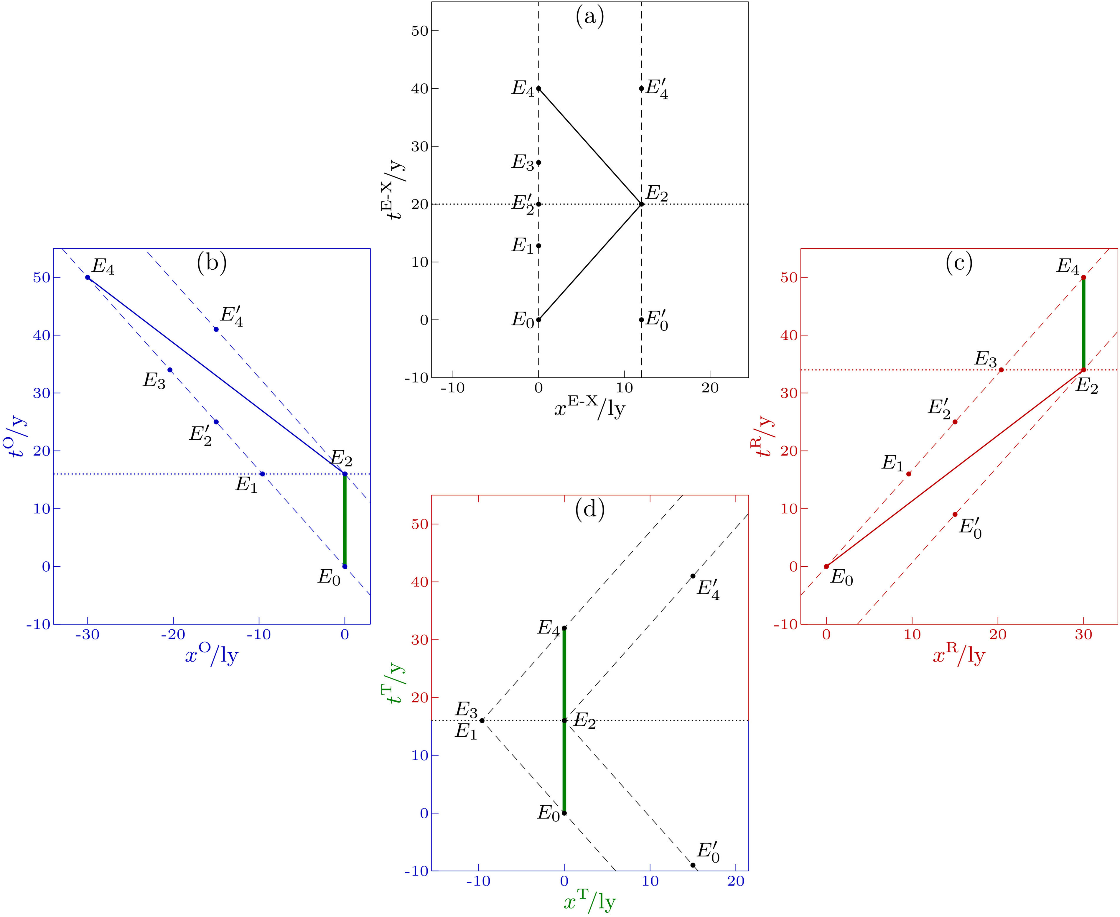
Figure 8 represents the positions of Earth, planet X and the traveler as observed from the three inertial frames involved. It has been drawn by setting (light-year), , which gives , and taking the departure from Earth, event , as a common origin for the frames E-X (a), O (b) and R (c). Part (d) represents a summary of the journey as observed by the traveler: the outward trip in frame O, and the return trip in frame R with the origins shifted to avoid a discontinuity in position and time coordinates.

The round trip of a twin represented in three diagrams using identical graphical scales: (a) frame E-X, (b) outward frame O, (c) return frame R. A summary of the journey as observed by the traveller is represented in (d). The dashed lines represent the positions of Earth and the other twin, and planet X. The continuous lines are for the position of the traveller, with the thick green lines indicating its state of rest.
The duration of the round trip as observed in frame E-X, the time elapsed between the events and , is given by
The results from the point of view of the traveller are obtained by computing the duration of the outward leg of the trip in frame O, and that of the return leg in frame R. In either of these frames, Earth and planet X are moving with speed and the distance between them is contracted. Thus,
Time dilation from the E-X frame gives the same result: both and are proper durations related, respectively, to the nonproper durations and . The total duration for the traveller is, then,
These results are represented by the thick green lines in Figure 8 (b), (c) and (d). At the end of the trip the twin that remained on Earth has aged 40 years, while the traveller has aged only 32 years.
Notice that , the duration of the round trip in frame E-X, is a proper time interval. Accordingly, in both frames O and R the associated dilated durations are .
In the literature the twin paradox is presented in two ways. The first considers the fact that the traveller returns younger than the other twin to be paradoxical. Clearly, this comes from thinking under the paradigm of absolute time. According to STR, time intervals are frame dependent as expressed by the LT, and the traveler has lived for less time than the twin that remained on Earth.
In the second version, the misinterpreted “symmetry” of time dilation is invoked: for the traveller the twin on Earth is moving and should be younger at the end of his “trip”. As already pointed out, time dilation is reciprocal but not symmetric between frames. As can be observed in Figure 8, the dilated and proper time interval pairs are, respectively, and (). As a result, time dilation from the point of view of the traveller does not account for the whole “trip” of the other twin. Just before his arrival at planet X, still in frame O, the time interval between events and which amounts to , due to the asynchrony between and , is in the future; right after the beginning of the return trip, in frame R, the asynchrony between and is inverted and the same time interval is already in the past.
Although usually associated with time dilation, the consequences of the evident asymmetry between the conditions of the twins are more easily explained by resorting to Lorentz contraction. Although reciprocal between frames, it is determinant for the traveller, but plays no role from the point of view of the twin on Earth.
To explain the twin paradox, some texts evoke a mysterious effect of the accelerations to which only the traveler is necessarily submitted. To rule out any effect of the acceleration on the different durations of the trip, consider a modified version of the problem. Both twins embark in identical spaceships and undergo the same sequence of acceleration processes as observed from frame E-X: 1) acceleration from rest to ; 2) slow down to rest; 3) reversal to ; and 4) slow down to rest. After each process, the traveller keeps moving with the acquired constant speed until the next, to go from Earth to planet X and back. The other twin undergoes the same four processes, but one immediately after the other ending up at rest on Earth where he awaits the return of the traveller. The elapsed times during the acceleration processes are identical for both twins and, therefore, the difference of ages at the end will result solely from the intervals of uniform motion, the traveller with constant speed and the other twin at rest.
The time dilation formula in its differential form, equation (25), permits to figure out the elapsed proper time of the traveller during the acceleration processes from the elapsed time in the inertial frame E-X. It is clear from the time dilation formula (25) that the proper time interval associated with an accelaration process is still reduced in comparison with the corresponding , though by a factor smaller than . Thus, taking acceleration into account will change quantitavively the overall result for the round trip, but not the fact that, at the end, the traveller will be younger than the other twin.
To get an estimate, consider acceleration with a constant modulus . For the example at hand, we get and a distance travelled during each of the four processes. Thus, the smaller reducing factor applies only to a small portion of the duration of the journey (). The correction that results from considering the acceleration could be made negligible by assuming a larger value for or a longer trip.
7. Final Comments
In this review of the kinematic part of Einstein’s STR, the physical meaning of the Lorentz Transformations was elucidated. This has been done by emphasizing basic aspects that, although implicit in the formulation of the theory, are sometimes overlooked in the literature and textbooks. The only consequence of the invariance of that distinguishes STR from its classical version is the relativity of simultaneity at a distance, which causes time intervals to be frame-dependent. The only difference between time in classical relativity and STR is the asynchrony – proportional to the distance along the direction of the relative motion – between the time coordinates of different inertial frames. Apart from this, time, and space as well, are completely equivalent in different inertial frames, just as they are in classical relativity. The numerous experiments involving comparisons of clocks in relative motion do confirm STR predictions, not its misinterpretations. Proper understanding of the physical meaning of the consequences of STR permitted to spot what is wrong in their unfortunate misinterpretations, which may be of help in teaching the subject.
The invariance of in STR represents the acknowledgement of a property of nature that we cannot fully “understand” based on our common sense. However, as it is well known, Physics is not based on common sense; on the contrary, the major advances of this science came from revoking long lasting paradigms based on it. If our daily experience involved speeds comparable to , its invariance and the related consequences could seem “natural” to us. But would that be real understanding?
I wish to express my gratitude to the anonymous reviewers for their comments, criticisms and suggestions. They were very valuable and contributed to turn the original version of the article into this improved final version.
Data Availability
This work is purely theoretical and does not rely on any datasets. No data were generated or analyzed in this study.
References
- [1] A. Einstein, Ann. Phys. 17, 891 (1905).
-
[2] International Bureau of Weights and Measures, The International System of Units (SI), available in: https://www.bipm.org/en/measurement-units
» https://www.bipm.org/en/measurement-units - [3] W. Rindler, Introduction to Special Relativity (Clarendon Press, Oxford, 1991), 2 ed.
- [4] P.G. Bergmann, Introduction to the Theory of Relativity (Dover, New York, 1976).
- [5] A.P. French, Special Relativity (Nelson, London, 1968).
-
[6] R.P. Feynman, R.B. Leighton and M. Sands, The Feynman Lectures on Physics, available in: https://www.feynmanlectures.caltech.edu/
» https://www.feynmanlectures.caltech.edu/ - [7] V. Berzi e V. Gorini, J. Math. Phys. 10, 1518 (1969).
- [8] E. Loedel, An. Soc. Cient. Argent. 145, 3 (1948).
- [9] H. Amar, Am. J. Phys. 23, 487 (1955).
- [10] H. Amar, Am. J. Phys. 25, 326 (1957).
- [11] R.W. Brehme, Am. J. Phys. 30, 489 (1962).
- [12] R.W. Brehme, Am. J. Phys. 32, 233 (1964).
- [13] E. Benedetto, M. Capriolo, A. Feoli e D. Tucci, Eur. J. Phys. 34, 67 (2013).
- [14] D.V. Redžić, Eur. J. Phys. 36, 065035 (2015).
- [15] P. Sikora, Eur. J. Phys. 39, 045707 (2018).