
 Development of a low-cost system for energy conversion coefficient measurements based on thermomagnetic phenomena
Abstract
This study presents the experimental development of a simple and low-cost system for measuring the thermomagnetic energy conversion based on the Anomalous Nernst Effect. The approach aims to provide an easy-to-implement alternative for teaching modern physics phenomena, such as the Anomalous Nernst Effect (ANE) and Longitudinal Spin-Seebeck Effect (LSSE), highlighting its educational potential and applicability in high school and higher education settings. The proposed system is validated through experimental measurements performed on specific samples, using advanced characterization techniques. The results demonstrate the system’s effectiveness, making experimentation accessible and relevant for students’ formation in physics, nanotechnology, and sustainable energy fields.
Keywords
Thermomagnetic phenomena; Nernst effect; Thin films
1. Introduction
The search for renewable energy sources has become a fundamental issue for the scientific community, especially given the urgent need to mitigate the socio-environmental impacts caused by fossil-based alternatives. In this context, different energy sources, such as wind and solar, have been at the forefront of the global energy transition. However, although on a smaller scale, other forms of energy recovery have gained attention due to their potential for scientific and technological innovation. Among these energy conversion approaches, the transformation of dissipated heat into electrical energy mediated by thermomagnetic phenomena stands out [1,2,3,4].
In this type of energy generation, nanostructured systems are connected to an instrument that provides dissipated heat during its operation, such as the surfaces of electric motors and industrial machines (Fig. 1(a)). If properly recovered, the dissipated heat can generate electrical energy with sufficient power to supply, for instance, sensors for temperature, vibration, or humidity monitoring of the motor or machine itself.
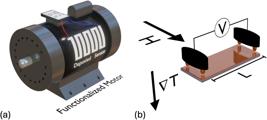
(a) Electric motor functionalized with a film/tape for thermomagnetic energy generation through ANE. (b) Vector configuration that maximizes the ANE signal. Here, is the constant magnetic field, intense enough to saturate the sample magnetically, is the temperature gradient applied perpendicular to the sample plane, and L is the distance between the electrical contacts.
Thermomagnetic and thermoelectric phenomena involve the direct conversion of temperature differences within a material into electrical energy [5]. These effects have attracted significant attention due to their high potential for technological applications, especially in the field of clean energy generation. Among the various thermoelectric effects, the Anomalous Nernst Effect (ANE) [6,7,8,9,10,11,12,13] stands out for its ease of detection and its potential for converting waste heat into usable electrical power.
The ANE occurs when a temperature gradient is applied perpendicular to the plane of a ferromagnetic material – that is, between its top surface and bottom [4, 6]. If the material exhibits spontaneous magnetization or is magnetized by an external magnetic field, an electric voltage can be generated across its lateral edges, as illustrated in Fig. 1(b). Mathematically, the phenomenon is represented by the following equation,
where is the unit vector in the direction of magnetization (), and SANE is related to the ANE coefficient (λANE) through,
where μ༚ is the magnetic permeability in vacuum and ms is the saturation magnetization of the ferromagnetic material.
Experimentally, potential differences can be measured from an electric field generated between two electrical contacts separated by a distance L (see Fig. 1(b)). Thus, we have,
However, these equations can be drastically simplified when a given field configuration (, and ) is considered, as described in detail in Section 4 of this study.
In addition to ANE, other phenomena, such as the Longitudinal Spin-Seebeck Effect (LSSE)1, require similar experimental setups and can be explored simultaneously. Both ANE and LSSE have strong technological and conceptual appeal, making them topics at the forefront of modern science. Thus, exploring these phenomena theoretically and experimentally through accessible experiments can be an important approach to studying modern physics. As is widely known, spintronics2 and thermomagnetic phenomena are fundamental areas of modern physics that explore the interaction between electron spin and its magnetic and thermal properties. These phenomena have revolutionary applications, such as high-efficiency magnetic memories (MRAM)3, and devices for converting thermal energy into electrical energy.
Within this context, the pedagogical approach of this study aims to promote a critical and scientific understanding of renewable energy sources based on magnetic effects.
The study of clean energy is fundamentally important in the daily life of schools and universities and should be treated as a priority. Currently, various educational projects at both high school and university levels explore this crucial topic in the classroom [14,15,16,17,18]. In this context, there are different ways to present the subject to the school community, and experimental methodology stands out as one of the most effective, enabling practical and engaging learning of key concepts. Another important aspect is the development of skills in scientific instrumentation, automation, and programming-fields that are increasingly attracting studentsâ attention. Even with little prior knowledge in instrumentation, systems based on open-source platforms like Arduino can greatly contribute to the technical education of students [19,20,21].
For high school education, it becomes an excellent alternative to explore modern physics concepts in experimental classes at this level, which is extremely relevant given the deficiency that many Brazilian schools have in this area of physics in their didactic laboratories [22, 23]. At the higher education level, understanding these concepts is crucial for formative purposes, not only leading to an adequate understanding of physics but also preparing students for possible professional dedication in experimental areas such as nanotechnology, materials science, and sustainable energy. However, the implementation of this experiment may face significant challenges within the context of our educational reality. Initially, the “maker” culture needs to be more strongly encouraged, not only among students but especially among educators. Although artificial intelligence can facilitate or reduce difficulties related to programming and automation, the assembly of experimental apparatus still requires demystification. Furthermore, despite having developed a low-cost system, it is well known that the majority of public schools lack both laboratories and educational Arduino kits.
This work presents the experimental development of a simple system for measuring the constant SANE. Additionally, we produced samples with specific characteristics and conducted experimental measurements to validate the functionality of the proposed equipment. However, to make the equipment and the development of experimental measurements accessible to any student, we used an anti-theft ferromagnetic TAG, to demonstrate the system’s functionality. In this sense, various advanced experimental techniques were employed to characterize the samples and measure the constants SANE under different experimental conditions. With this, we aim to demonstrate the consistency of the operation of this low-cost instrumentation, with simple assembly and remarkable didactic potential.
2. Instrumentation Development
2.1. Equipment assembly
The scientific instrumentation was assembled using accessible electronic components that offer high precision. Additionally, the entire platform is built around an ATmega328 (Arduino Nano) open-source controller board, which is designed to be user-friendly and easy to program.
The project involves assembling an experimental system capable of controlling and measuring the temperature difference between the top and bottom of the sample to infer the temperature difference ΔT, as illustrated in Fig. 2(a) and (b). To increase the efficiency of the phenomenon and maximize the value of ΔT, a high-efficiency Cooler was used, which can be easily obtained from discarded computers. This component’s role is to maintain the so-called “cold sink” at room temperature, while the “hot sink” is heated by a resistive heater. In this setup, a 3D printer heating cartridge, easily acquired from electronics stores, was used4. Specifically, the heating cartridge is powered by a 12 V (200 mA) power supply5 connected to a relay module for electronic activation.
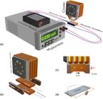
(a) General schematic overview of the proposed system. (b) Details of the instrumentation for measuring the thermomagnetic efficiency of ferromagnetic materials. The magnetic bars are composed of NdFeB permanent magnets with an induced magnetic field in the transverse section. The thermal sinks are copper blocks, a material with high thermal conductivity. The cold thermal sink is placed in contact with the high-efficiency Cooler, connected to a 5V power source. The temperature sensors used are NTC type, low-cost, and highly precise sensors. (c) Side view of the proposed system indicating the configuration of the vectors defining the magnetic field to magnetize the material and the temperature gradient (applied perpendicular to the studied sample plane). (d) Schematic representation of the assembly of electrical contacts using gold-plated springs, taken from a phone charger. Real images can be observed in Figure 3.
The measurement of the temperature difference between the upper and lower parts of the sample is performed using NTC (Negative Temperature Coefficient) temperature sensors, which are low-cost and highly precise6. The β value, needed to calibrate the NTC sensors, was obtained by comparing the experimental temperature of NTCs with a commercial thermocouple (K-Tipe), connected to a digital multimeter.
Finally, it is necessary to measure the thermomagnetic potential difference, requiring a measurement system in which electrical contacts are quickly and easily attached to the sample’s extremities. For this purpose, these contacts must have high electrical conductivity. To minimize costs, gold-plated spring-loaded electrical contacts, commonly found in phone chargers, were utilized, as shown in Fig. 2(c). These contacts are connected to a benchtop multimeter with a minimum precision of 51/2 digits. The equipment allows measuring potential differences in the order of μV, typical values measured with the proposed configuration.
As described in the theoretical review above, the thermomagnetic signal of the potential difference between the contacts is linearly proportional to the material’s magnetization. Thus, to maximize the electric field in the sample, a ferromagnetic sample must be brought to magnetic saturation. In this case, using magnetic bars allows achieving sufficiently intense magnetic fields for this purpose. In the presented setup, a magnetic field of approximately 1.0kOe is established (see Fig. 2(a)).
Figure 3 depicts images of the real experimental setup proposed in this study. On the left side of the figure, we observe the high-efficiency cooler obtained from a PC. The right top image depicts the copper bars (hot and cold sinks) as well as the NTC sensors used to measure the ΔT on the sample. Finally, the right bottom image shows the spring gold contacts used to measure the thermomagnetic voltage in the system.
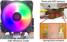
Image of the experimental system proposed in this study. On the left, the high-efficiency cooler is depicted. In this case, the system is composed of an aluminum dissipator connected to Heat pipes composed of copper in which a working fluid is present. On the right top, it is possible to verify the copper sinks in which the sample is connected using thermal paste. The NTC sensors are inserted into the holes to provide the best electrical contact in the system. Finally, on the bottom right, the spring gold contacts are presented; these contacts are connected to the digital multimeter for the thermomagnetic voltage.
2.2. Automation and user interface development
In addition to the experimental setup, the instrumentation development includes automation and user interface development. The ATmega 238 controller board is responsible for interpreting the electrical signals from the NTC sensors connected to the cold and hot thermal sinks to obtain a temperature value. The schematic diagram for this system is represented in Fig. 4.

Schematic diagram of the connections of the NTC sensors and the relay for activating the heating cartridge on the ATmega 238 controller board.
The code was developed within the Arduino platform’s integrated development environment (Arduino IDE) to provide an interface with communication commands for the temperature sensors and relay module, which acts as an electronic switch to turn the heating cartridge on and off. The code used to control the temperature sensors can be found in Supplementary Material of this document. Regarding the potential difference measurements with the multimeter, these can be checked manually on the display or recorded using hardware integration programs with open-source languages such as Python or commercial software like LabVIEW. In this case, Python software was considered, and the user interface can be visualised in Supplementary Material. In particular, the experimental data is can be saved in any directory and will be composed by four collumns, indicating the thermoelectric voltage (V), temperature of the hot sink (Th), temperature on the cold sink (Tc), and the temperature difference between the NTC sensors (DT).
3. Materials and Methods
3.1. Sample preparation
To verify the functionality of the assembled system and perform the experimental measurement of thermomagnetic efficiency, thin films of Ni81Fe19 with thicknesses of 20, 40, and 60 nm were produced. The Ni81Fe19 alloy, commercially known as Permalloy is widely used in the production of hard disks and the development of magnetic sensors due to its high magnetic permeability and extremely favorable magnetic properties for low-field applications. Moreover, for the deposition ratio obtainment, a 30 nm thick NiFe was deposited for X-ray reflectance characterization (as described below).
The goal of conducting tests in nanometric systems is related to assessing the sensitivity of the proposed equipment. Considering that magnetic volume and electrical resistance are fundamental for this type of study, performing validation tests using samples with low thicknesses (and consequently low “magnetic volume”) is crucial. Furthermore, to ensure that the measured signal originates from the ANE phenomenon, a nanostructure of 30 nm Ag (Silver), a non-ferromagnetic material, was also deposited.
Thus, we can verify the system’s response using a material that does not respond to ferromagnetic phenomena, which allows for the detection of any unwanted tension not originating from the ANE phenomenon explored here.
At the same time, to make the procedure accessible to any user, ferromagnetic samples were obtained from anti-theft tags (TAGs)7, details of its operation can be found in these references [24,25,26]. These TAGs are composed of high-permeability ferromagnetic ribbon based on Cobalt and Iron (CoFe) and can be found in various products in department stores, making them easily accessible for any user. Within this purpose, the ferromagnetic TAGs were removed from the plastic wrap before use.
The production of thin films was carried out in a deposition system that uses magnetron sputtering. This technique consists of depositing atoms or clusters of atoms from a target with the desired composition onto a substrate. It is a widely used method in nanomaterial research. For more information on the technique, we recommend reading ref. [27, 28].
In this work, to produce high-quality samples, the deposition chamber was first evacuated to a vacuum of approximately 6×10⁻⁶ Torr (8×10⁻⁴ Pa). To create a suitable environment for deposition, a noble gas pressure (to prevent unwanted reactions) is required. In this case, an Argon (Ar) pressure of 3×10⁻³ Torr (0.4 Pa) was used. A power of 30 W (420 V) was then applied between the target and the substrate to initiate the thin film deposition. During the film deposition, an external field of approximately 500 Oe was applied to the glass substrate, with dimensions of 4×12 mm2, to induce an easy magnetization axis, that is, a uniaxial magnetic anisotropy [29, 30]. In particular, this field was applied perpendicular to the main axis of the sample.
3.2. Structural, magnetic, thermomagneticcharacterization
To verify whether the film has the desired thickness, the X-ray Reflectance (XRR) technique allows the thickness of a thin layer of a specific material to be determined, based on Bragg’s Law [31]. At the same time, X-ray Diffraction (XRD) measurements at high angle values were performed to assess the structural properties of the produced samples. For these measurements, a Rigaku X-ray Diffractometer, model MiniFlex, with a Cukα X-ray source of wavelength λ = 1.54 Å was used. For XRR, angles between 2° and 5° were considered, while for XRD, measurements were taken between angles of 10° and 80°. In the latter case, all thin films and the anti-theft TAG exhibited amorphous structural properties, so they will not be shown here.
Magnetic properties were measured on a 12×4 mm2 sample, using a Vibrating Sample Magnetometer (VSM) from LakeShore (7400 series) with a magnetic field of ±300 Oe applied in the plane of the thin film/TAG. Measurements at different angles between the magnetic field and the main direction of the sample were conducted to check for the presence of magnetic anisotropy.
Finally, the system presented in the previous section was used to measure the thermomagnetic efficiency of the produced samples, as well as the magnetic tape removed from the anti-theft TAG. To this end, the temperature difference (ΔT) was varied from 0 K to approximately 30 K. It is important to note that ΔT represents the temperature difference measured between the top surface of the sample and the bottom of the glass substrate, on which the nanostructures were deposited.
4. Results and Discussion
Initially, the XRR results for the 30 nm thick NiFe film, specially produced for this characterization, are presented. This technique allows us to verify the thickness of a thin film based on Bragg’s Law. By knowing the deposition time, we can calculate the deposition rate (τ) in nm/s for a given deposition parameters set. Fig. 5 shows the XRR results obtained for the 30 nm NiFe thin film. From the curve, it is possible to identify the Bragg peaks. Taking the 2θ peak position and indexing each peak the q vector can be calculated using [32],

XRR results of 30 nm thick NiFe film as a function of the 2θ angle. The inset shows the scattering vector q as a function of the peak indices of XRR results.
Where λ is the X-ray wavelength, for the Cukα radiation in this case. For a flat thin layer, the q vs. indice curve should exhibit a linear behavior where the slope is connected with the film thickness (tf) though
Where AP is the angular parameter (slope) of the curve. The inset in Fig. 5 depicts this behavior for our thin film. In our case, a nominal thickness of 34 nm was deposited during 300 s. These parameters provide a deposition ratio of τ = 0.113 nm/s
We now begin the analysis of magnetic results, which will serve as the basis for the following discussions on thermomagnetic response. Initially, we performed magnetization measurements of the deposited thin films. As described earlier, we deposited NiFe films with three different thicknesses to test the sensitivity limit of the proposed system. Additionally, we used part of a ferromagnetic TAG obtained from an anti-theft system. Thus, Figs. 6(a–c) present the normalized magnetization curves8 (M/MS) of the thin films, measured in two different directions (θ) relative to the field applied during the deposition. Here, θ = 0° refers to the curve measured along the direction of the magnetic field applied, i.e., the easy magnetization axis. On the other hand, for θ = 90°, the measurement provides information on the magnetic properties when the external field is applied perpendicular to the easy magnetization axis. Specifically, Fig. 6(a) shows the normalized magnetization curves obtained for the NiFe thin film with 20 nm thickness.

Magnetic hysteresis curves are measured in diferent directions relative to the easy magnetization axis. For θ = 0°, the magnetic field is applied along the direction of the field used during the deposition of the thin films. The insets in each figure show a limited field range to detail the coercive field and remanence for each thin film. (a) Magnetization curves for the 20 nm thick Py film. (b) Results for the 40 nm thick sample. (c) Results for the 60 nm thick sample. (d) Magnetic hysteresis curves were measured in different directions relative to the easy magnetization axis for the TAG ferromagnetic material selected for this study.
Analyzing the results, we observe a film with soft magnetic properties, meaning it has a low coercive field (Hc) and high remanent magnetization (Mr), which is characteristic of the alloy used. By examining the curves in a reduced field range (inset in the figure), we can observe that the curves measured at different angles θ exhibit slightly different behavior. The measurement along the easy magnetization axis (blue curve) shows a high remanent magnetization and a coercive field of approximately 8.0 Oe. On the other hand, the curve measured along the hard magnetization axis (black curve) shows that, although the coercivity remains nearly unchanged, there is a considerable decrease in remanent magnetization. However, regardless of the direction of the external field measurement, the most important property is the magnetic field required to saturate the sample, i.e., the saturation magnetic field (Hs). In this case, a field of Hs≈10 Oe is sufficient to saturate the sample and lead to a constant magnetization response in the hysteresis curves. This property is crucial for thermomagnetic applications because, when the sample is in its saturated state, we achieve greater efficiency in the thermomagnetic response, as discussed in the introduction of this work. A similar behavior was observed for the sample deposited with 40 nm thickness, as shown in Fig. 6(b). In this case, we observe a slight decrease in coercivity (≈ 5 Oe) and remanent magnetization. Consequently, the magnetic field required for complete saturation of the sample (Hs), regardless of the measurement direction, is approximately 8.0 Oe. On the other hand, for the 60 nm thick film (Fig. 6(c)), we notice that the induced anisotropy decreases. This characteristic is observed when analyzing the results for reduced fields, where we can see a similar behavior between the two directions. This phenomenon is related to the increase in stored stress in the nanostructure as the thickness increases, leading to a degradation of the induced anisotropy [8, 33, 34]. Nevertheless, in this case, we observe that a field of 30 Oe is sufficient to saturate the thin film magnetically. It is important to note that the field generated by the permanent magnets in the proposed thermomagnetic system is approximately 1.0 kOe, which is an intense field capable of saturating all the films studied here.
Now, considering the ferromagnetic TAG selected for thermomagnetic measurements in the proposed system, the magnetization curves in two different directions are presented in Fig. 6(d). Here, we observe a magnetically isotropic behavior. This indicates that, regardless of the direction of the magnetization measurement relative to the sample axis, the magnetic behavior remains unchanged. This property is important for applications in anti-theft TAGs and is characteristic of CoFe-based tapes produced by melt spinning [35,36,37]. Moreover, in the saturation state is reached at around 150 Oe. Therefore, once again, the field generated by the permanent magnets in the proposed thermomagnetic system is intense enough to saturate the ferromagnetic TAG.
In general, all the ferromagnetic samples studied here could be used in our system, as the field of 1.0 kOe would saturate them and maximize the thermomagnetic response.
First, the thermomagnetic results measured with the proposed system on NiFe thin films produced by Magnetron Sputtering are presented. As mentioned in the introduction, experimentally, we can simplify the vector equations presented. To do this, it is needed to consider specific configurations for the experimental procedure. This feature is particularly important to provide a single understanding of the effect, making the experimental setup accessible for any high school or undergraduate student.
Considering that the sample is magnetically saturated during the entire measurement process and that the magnetization is aligned perpendicular to the electrical contacts as shown in Fig. 1(b), we can simplify Eq. 1 in the form,
where ∇Ta = ΔTa/ta, and ΔTa is the temperature difference between the top and bottom parts of the thin film and substrate assembly, with total thickness ta, i.e., ta = tf + ts, where tf is the thickness of the ferromagnetic film and ts is the thickness of the substrate. Thus, the maximum voltage (Vmax) measured is given by the following expression:
As we can observe, the voltage generated by the system should follow a linear behavior with the temperature difference ΔTa.
Fig. 7(a) shows the thermomagnetic measurements for the NiFe thin films as a function of the measured ΔTa.
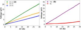
Thermomagnetic measurements performed by the proposed system on NiFe thin films with different thicknesses. (b) Thermomagnetic measurements performed on CoFe-based TAG and Ag thin film.
Regardless of the film thickness, a well-defined linear behavior is observed. Furthermore, even for the thinnest film (20 nm), we were able to measure the theoretically predicted thermomagnetic behavior. Considering a linear function, we are able to fit the thermomagnetic curves and predict the energy conversion efficiency from thermal to electrical energy for each studied film. In Fig. 7(a), the closed circular symbols represent the experimental results, while the solid line is the mathematical fit obtained for the data. Here, the angular parameter of the curve (AP) is related to the SANE through the following relation:
using Eq. 7, we get:
Finally, isolating SANE, we have:
That is the energy conversion power of the film-substrate assembly to convert thermal energy into electrical energy, since we have not accounted for the substrate’s contribution. Here, the higher the value of SANE, the greater the material’s ability to convert energy.
Moreover, as seen in Eq. 10, increasing the thickness of the ferromagnetic material (tf) can lead to an increase in the measured thermomagnetic efficiency. In our case, the substrate thickness for all three films is the same. Thus, the increase in SANE is associated with the increased thickness of the studied sample.
The results obtained for the CoFe-based ferromagnetic TAG are presented and analyzed. For comparison and to verify the thermomagnetic origin of the observed effects, a thin Ag film was also fabricated and measured, as shown in Fig. 7(b). In the case of the CoFe-based TAG, the thermomagnetic response exhibits a clear linear dependence on the temperature difference ΔTa, in agreement with theoretical predictions.
Furthermore, it is evident that the thermomagnetic voltage achieved for the CoFe-based ferromagnetic TAG is considerably higher than that found in the films. This is due to the difference in the sample structure. While in the NiFe thin films the temperature difference ΔTa is applied to the film-substrate assembly, for the CoFe-based TAG, the same temperature difference is applied to the TAG and a Kapton adhesive, which is used to electrically isolate the TAG from the sample holder.
In this same figure, we can also observe the behavior of the Ag thin film. In this case, there is no significant change in the measured electrical voltage as the temperature difference increases. We observe a negligible increase, possibly associated with the galvanomagnetic voltage resulting from heating the electrical contacts.
Once again, the curve fitting of the CoFe-based TAG in Fig. 7(b) was performed using a linear function to obtain the angular parameter (AP).
To calculate the SANE for all the ferromagnetic samples studied, we need some experimental parameters, such as substrate thickness, distance between contacts during the experiment, and the thickness of the films or TAG. Using these data and considering Eq. 10, SANE can be obtained. Table 1 presents the parameters and the main results obtained for this study. It is worth noting that the results found here are consistent with those found in the literature for films and TAGs with similar compositions and thicknesses [4, 6, 38], validating our proposed experimental system.
Experimental data for the samples studied regarding magnetization curves and the Anomalous Nernst Effect (ANE).
Thus, for the purpose of thermal energy conversion into electrical energy, SANE is the most important parameter for analysis, as thin films will always be based on substrates. Therefore, the analyses presented in Table 1 are the ones that will be practically applied in our daily routine9.
Conclusion
In conclusion, this study presents an easy-to-use and cost-effective system for exploring frontier phenomena in science at the high school and undergraduate levels. The ANE and LSSE phenomena play a significant role in thermomagnetic energy conversion and can be investigated from multiple perspectives. These effects can be studied within the framework of Spintronics and magnetic materials in modern physics applications, as well as in the context of renewable and clean energy production. The proposed system was extensively tested using ferromagnetic nanostructures and TAGs. Structural, magnetic, and thermomagnetic characterizations were conducted to validate its performance. The results highlight the systemâ s potential, particularly its high sensitivity to low magnetic volume samples. The obtained SANE values from experimental measurements are consistent with those reported in the literature, demonstrating the systemâ s reliability and ease of use. Beyond assembling the experimental apparatus, we provide a step-by-step guide on how to determine the relevant experimental parameters and conduct the corresponding analyses. However, it is important to point out that the main pedagogical limitation of applying this instrumentation at the high school level lies in the absence of the specific scientific concepts involved in the standard curriculum. As a result, these topics would need to be introduced either as integrative themes or through elective subjects. However, in undergraduate settings, this limitation is significantly reduced. The only requirement would be to incorporate the proposed instrumentation into the syllabus of experimental modern physics courses, in programs where such courses are already offered. Moreover, about future pedagogic applications, especially at the university level, it is of utmost importance to provide high-quality pedagogical tools that not only support foundational learning but also allow students to engage with cutting-edge scientific research. The proposed system aligns perfectly with this objective, enabling hands-on exploration of contemporary topics in spintronics, nanotechnology, and energy conversion.
Supplementary Material
The following online material is available for this article: Appendices.
Acknowledgments
CMV, FB, and MAC would like to thank CNPq for the financial support through the Research Productivity Grants, as well as CAPES for the funding provided to the students of the Magnetism Group (GMAG) and the Laboratory of Physical Properties of Ceramic Materials (LaPFiMC). The authors also thank the INCT of Spintronics and Advanced Magnetic Nanostructures (INCT-SpinNanoMag), CNPq 406836/2022-1.
Data Availability
The entire dataset supporting the results of this study is available upon request from the corresponding author, M. A. Correa. The dataset is not publicly available due to the complexity and organization of the obtained data and the programming involved.
-
Funding
CMV, FB, and MAC would like to thank CNPq for the financial support through the Research Productivity Grants, as well as CAPES for the funding provided to the students of the Magnetism Group (GMAG) and the Laboratory of Physical Properties of Ceramic Materials (LaPFiMC). The authors also thank the INCT of Spintronics and Advanced Magnetic Nanostructures (INCT-SpinNanoMag), CNPq 406836/2022-1.
References
- [1] K.I. Uchida, H. Adachi, T. Ota, H. Nakayama, S. Maekawa and E. Saitoh, Appl. Phys. Lett. 97, 172505 (2010).
- [2] J. Holanda, O.A. Santos, R.O. Cunha, J.B. Mendes, R.L. Rodríguez-Suárez, A. Azevedo and S.M. Rezende, Review B 95, 214421 (2017).
- [3] S. Pandya, J. Wilbur, J. Kim, R. Gao, A. Dasgupta, C. Dames and L.W. Martin, Nat. Mater. 17 432 (2018).
- [4] M.A. Correa, A. Ferreira, A.L.R. Souza, J.M.D. Neto, F. Bohn, F. Vaz and G.V. Kurlyandskaya, Sensors 23, 1420 (2023).
- [5] D. Champier, Energy Conversion and Management 140, 167 (2017).
- [6] A.S. Melo, A.B. Oliveira, C. Chesman, R.D.D. Pace, F. Bohn and M.A. Correa, Scientific Reports 9, 15338 (2019).
- [7] M. Gamino, J.S. Santos, A.R. Souza, A. Melo, R.D. Pace, E. Silva, A. Oliveira, R. Rodríguez-Suárez, F. Bohn and M. Correa, Journal of Magnetism and Magnetic Materials 527, 167778 (2021).
- [8] H. Kannan, X. Fan, H. Celik, X. Han and J.Q. Xiao, Scientific Reports 7 6175, (2017).
- [9] M. Manikandan, A. Ghosh and R. Mahendiran, The Journal of Physical Chemistry C 126, 1152 (2022).
- [10] M. Soroka, K. Knížek, Z. Jirák, P. Levinský, M. Jarošová and J. Buršik, Physical Review Materials 5, 035401 (2021).
- [11] G.H. Park, H. Reichlova, R. Schlitz, M. Lammel, A. Markou, P. Swekis, P. Ritzinger, D. Kriegner, J. Noky, J. Gayles et al, Physical Review B 101, 060406 (2020).
- [12] C.D.W. Cox, A.J. Caruana, M.D. Cropper and K. Morrison, Journal of Physics D: Applied Physics 53, 035005 (2020).
- [13] J. Hu, Y. Zhang, M.A. Cabero Z, B. Wei, S. Tu, S. Liu, D. Yu, J.P. Ansermet, S. Granville and H. Yu, Journal of Magnetism and Magnetic Materials 500, 166397 (2020).
- [14] M. Qamruzzaman, M. Monika and R. Kler, Int. J. Energy Econ. Policy 15, 301 (2025).
- [15] S. Zheng, J. Li, W. Lu, M. Hafeez, M.T. Sohail, M.W. Akbar and R.W. Attar, Renew. Energy 238, 121934 (2025).
- [16] A.E. Silva Coelho, J.V. Chaves, M.F. Silva Carneiro, M.S. Souza and A.D.S. Silva, Nordeste Mineiro 6, 1 (2025).
- [17] C.P. Tieghi, F.L. Caneppele, A. Dal Pai, E.Z. Godinho, C.F.M. Almeida, D.C. Malagueta and M.M. Frigo, Rev. Bras. Climatol. 36, 170 (2025).
- [18] F.A. Santos, L.M. Gomes, J.G.S. Lima Jr., R.D.M. Gester and L.M. Gomes Jr., Sci. Plena 13 012718 (2017).
- [19] C. De Oliveira Fernandez, L.C. Biazon, A.A.G. Martinazzo, I.K. Ficheman and R.D Lopes, RENOTE 13,1 (2016).
- [20] M.P.C. Moreira, M.C. Romeu, F.R.V. Alves and F.R.O. Silva, Caderno Brasileiro de Ensino de Física 35, 721 (2018).
- [21] S. Silveira and M. Girardi, Revista Brasileira de Ensino de Física 39, e4502 (2017).
- [22] M.L.F. Andrade and V.G. Massabni, Ciência & Educação (Bauru) 17, 835 (2011).
- [23] F. Bassoli, Ciência & Educação (Bauru) 20, 579 (2014).
- [24] P. Ripka, Journal of Physics: Conference Series 450, 012001 (2013).
-
[25] Apex Magnets, How Anti-Theft Tags Work, available from: https://www.apexmagnets.com/news-how-tos/how-anti-theft-tags-work/, accessed in 15/05/2025.
» https://www.apexmagnets.com/news-how-tos/how-anti-theft-tags-work/ -
[26] Checkpoint Systems, How Does RF Technology Work?, available from: https://checkpointsystems.com/apparel-labeling-solutions/how-does-rf-technology-work/, accessed in 15/05/2025.
» https://checkpointsystems.com/apparel-labeling-solutions/how-does-rf-technology-work/ - [27] M.A. Correa, A.V. Svalov, A. Ferreira, M. Gamino, E.F. Silva, F. Bohn, F. Vaz, D.F. Oliveira and G.V. Kurlyandskaya, Sensors 23, 7781 (2023).
- [28] M. Correa, W. Rosa, A. Melo, E. Silva, R.D. Pace, A. Oliveira, C. Chesman, F. Bohn and R. Sommer, Journal of Magnetism and Magnetic Materials 480, 6 (2019).
- [29] A.T. Hindmarch, A.W. Rushforth, R.P. Campion, C.H. Marrows and B.L. Gallagher, Phys. Rev. B 83, 212404 (2011).
- [30] C.G. Kim, K.J. Jang, D.Y. Kim and S.S. Yoon, Appl. Phys. Lett. 77, 2114 (1999).
- [31] Z. Kaszkur, Journal of Applied Crystallography 33, 87 (2000).
- [32] M. Nayak and G.S. Lodha, Molecular, and Optical Physics 2011, 649153 (2011).
- [33] P.R. Kern, O.E. Silva, J.V. Siqueira, R.D.D. Pace, J.N. Rigue and M. Carara, Journal of Magnetism and Magnetic Materials 419, 456 (2016).
- [34] E.F. Silva, M.A. Correa, R.D.D. Pace, C.C.P. Cid, P.R. Kern, M. Carara, C. Chesman, O.A. Santos, R.L. Rodríguez-Suárez, A. Azevedo et al, Journal of Physics D: Applied Physics 50, 185001 (2017).
- [35] Z. Zhu, S.W. Or and G. Wu, Applied Physics Letters 95, 032503 (2009).
- [36] A. Svalov, S. Andreev, A. Arkhipov, E. Kudyukov, D. Neznakhin, A. Larrañaga and G. Kurlyandskaya, Journal of Physics: Conference Series 1389, 012100 (2019).
- [37] Y. Nykyruy, S. Mudry, Y. Kulyk, V. Prunitsa and A. Borysiuk, Physics and Chemistry of Solid State 24, 106 (2023).
- [38] N. Siqueira, A. Morais, J. Oliveira, C. Valença, J. Rodriguez, F. Bohn, A. Ferreira, C. Lopes, F. Vaz, D. Hotza et al., Journal of the European Ceramic Society 44, 116787 (2024).
-
1
Longitudinal Spin Seebeck Effect (LSSE): is a phenomenon similar to the Anomalous Nernst Effect (ANE), requiring the same experimental configuration and magnetic field conditions. However, in the LSSE, the conversion of thermal energy into electrical energy is mediated by the transformation of charge current into spin current. This feature is particularly appealing because spin currents do not produce Joule heating, which significantly reduces energy dissipation in electronic circuits. Nevertheless, it is important to note that the voltage generated by the LSSE is considerably lower than that of the ANE. As a result, ongoing research efforts aim to enhance the LSSE response and make it a viable approach for clean energy generation.
-
2
Spintronics: Modern electronics relies on the movement of electrons to generate current and transmit information through electronic systems. However, this electron flow results in significant energy dissipation due to the well-known Joule effect. In recent years, a new approach to information transport has emerged-one that does not depend on the motion of the electron itself, but rather on a fundamental property of the electron known as spin. This field of study is called spintronics. In spintronics, it is the spin of the electron that carries information, while the electron remains stationary. This fundamental difference drastically reduces-or even eliminates-Joule heating, thereby minimizing energy loss in electronic systems.
-
3
MRAM (Magnetoresistive Random Access Memory): is an advanced type of RAM that uses magnetic properties to store data, instead of electric charges like traditional memories. It operates based on the magnetoresistance effect, where electrical resistance changes depending on the alignment of magnetic moments in ferromagnetic layers. This allows MRAM to be non-volatile, meaning it retains data even when the power is off, while also offering high read/write speeds, low power consumption, and excellent durability. These features make MRAM a strong candidate to replace both volatile and non-volatile memory in various technological applications.
-
4
The 24V heating cartridge has an average price of U$ 8.00 in specialized stores.
-
5
The power supply can be a simple phone charger or purchased for an average price of U$ 3.00 in specialized stores.
-
6
The sensor costs around U$ 0.10 in specialized stores.
-
7
The operating principle of a ferromagnetic anti-theft tag is based on the magnetostrictive properties of the ferromagnetic alloy from which it is made. These systems typically consist of two or three ferromagnetic strips: one made of a magnetostrictive ferromagnetic material, and another of a hard magnetic material. When the tag is exposed to a low-frequency electromagnetic wave (approximately 60 kHz), and if the magnetic system is active, it will oscillate and emit electromagnetic radiation. For this reason, transmitter and receiver antennas are usually installed at store entrances to detect active tags passing through, triggering an audible and/or visual alarm.
-
8
Normalized magnetization (M/MS) is commonly used for measurements on nanostructures deposited on a substrate. In this case, the magnetic moment during the hysteresis curve is divided by the maximum magnetic moment obtained during the measurement, normalizing the magnetic hysteresis curve.
-
9
However, it is important to note that even though thermomagnetic efficiency (SANE) increases, the ANE coefficient (λANE) should be a property of the ferromagnetic film and, theoretically, does not exhibit dependence on the thickness of the studied thin film. To verify this aspect, we need to consider the temperature difference in each of the layers that make up our sample. More specifically, we need to calculate the temperature difference on the ferromagnetic film Δtf, taking into account its thickness tf as well as its thermal conductivity constant Kf. At the same time, since this film is based on a substrate (glass in this case), the substrate’s thickness ts and its thermal coefficient Ks should also be included in the energy balance. The correlation between the temperature difference measured during the experiment (between the top of the sample and the bottom of the substrate) and the temperature difference imposed on the thin film is given by [6], Thus, to calculate the ANE coefficient (λANE), we need to reduce the temperature ΔTa to ΔTf and rewrite Eq. 7 in terms of tf.
Edited by
-
Editor-in-Chief:
Marcello Ferreira https://orcid.org/0000-0003-4945-3169


