
 Design and experiment of an adaptive height adjustment system for soybean harvester header
ABSTRACT
The objective of this study was to design an adaptive header height control system through soybean pod height analysis in saline-alkali soils, ensuring consistent stubble height for optimal harvesting quality. The system includes a mechanical profiling device, angle sensors, a programmable logic controller (PLC) control unit, solenoid valves, a double-acting hydraulic cylinder, and a human-machine interface. The profiling device, comprising a parallelogram mechanism and a height detection unit, establishes a functional relationship between the rotation angle of the soil-contact component, header height, and hydraulic cylinder extension, clarifying its working principle. A multi-body dynamic - discrete element method (MBD-DEM) model simulated the profiling device’s performance in saline-alkali soils and guided its optimization. A mathematical model of the adaptive height control system was developed with a fuzzy proportional-integral-derivative controller to enhance precision. Field tests, using header speed and stubble height as variables, showed the average stubble height deviation was under 4 mm, the coefficient of variation below 0.08, and control error within 10 mm. These results confirm the system’s high precision and ability to maintain consistent stubble height in saline-alkali soybean harvesting, offering strong support for further development of adaptive height control technologies for headers.
Key words:
MBD-DEM; height detection; fuzzy-PID
HIGHLIGHTS:
Improving the cutting consistency of the header can reduce the harvest loss.
Using the profiling device, the real-time cutting height can be detected.
Fuzzy proportional-integral-derivative controller (PID) can significantly improve the response speed of the control system.
RESUMO
Este estudo teve como objetivo projetar um sistema adaptativo para controle da altura do cabeçote, por meio da análise da altura das vagens de soja em solos salino-alcalinos, garantindo um tolete consistente e uma colheita de qualidade. O sistema integra um dispositivo mecânico de perfilamento, sensores de ângulo, unidade de controle programmable logic controller (PLC), válvulas solenóides, cilindro hidráulico de dupla ação e interface homem-máquina. O dispositivo, composto por um mecanismo de paralelogramo e uma unidade de detecção de altura, estabelece a relação entre o ângulo de rotação do componente de contato com o solo, a altura do cabeçote e a extensão do cilindro, elucidando seu funcionamento. Um modelo multi-body dynamic - discrete element method (MBD-DEM) simulou o desempenho do dispositivo em solos salinos e alcalinos, orientando sua otimização. Além disso, desenvolveu-se um modelo matemático do sistema com um controlador fuzzy proportional-integral-derivative controller (PID) para aprimorar a precisão. Testes de campo, considerando a velocidade do cabeçote e a altura dos restolhos, demonstraram que o desvio médio foi inferior a 4 mm, o coeficiente de variação permaneceu abaixo de 0,08 e o erro de controle, dentro de 10 mm. Esses resultados evidenciam a alta precisão do sistema e sua capacidade de manter uma altura consistente dos restolhos na colheita da soja, reforçando o potencial para o desenvolvimento futuro de tecnologias adaptativas de controle de altura para cabeçotes.
Palavras-chave:
MBD-DEM; detecção de altura; PID fuzzy
Introduction
Soybean is an important economic crop (Carreira et al., 2024). However, current mechanized soybean harvesting is associated with a high loss rate that severely affects harvest quality (Lambrecht et al., 2023). In addition, saline-alkali soils impose stress on soybean growth, generally resulting in lower podding heights (Wang et al., 2014). Combined with the inadequacies in mechanized harvesting technology, the mismatch between the header cutting height and the soybean podding height easily leads to issues such as missed cutting, soiled pods, and pod shattering, thereby exacerbating the overall loss rate (Paixão et al., 2017). Notably, the losses incurred during mechanized soybean harvesting are primarily attributed to the header section, which accounts for approximately 80% of the total harvesting losses (Zhang et al., 2024).
To ensure the consistency of cutting height of soybean header, John Deere company has developed the 200 series header equipped with flexible cutter, which can achieve a certain degree of mechanical profiling and ensure the cutting height, but the profiling range is limited in complex ground conditions (Wang et al., 2024). Li et al. (2024) designed a soybean header profiling device combining mechanical and hydraulic technology, which expanded the profiling range of soybean header, but the device has not been verified in the undulating field. Jin et al. (2022) designed a main-subsidiary plate compression profiling mechanism, but did not verify the accuracy of the stubble height. Liu et al. (2023) designed an automatic control system for the height of the header to achieve accurate control of the height of the header, thereby enhancing the consistency of the height of the soybean stubble. Zhang (2019) proposed a fuzzy adaptive PID control strategy, combined with ultrasonic array sensors and mechanical profiling mechanism, to achieve a high degree of accurate detection of complex terrain, but the sensor cost is high, and vulnerable to field dust interference.
The existing conventional header height adjustment methods exhibit limited profiling range and are inapplicable to saline-alkali soil conditions. Therefore, this study aims to design an adaptive header height adjustment system through soybean pod height analysis in saline-alkali soils, ensuring consistent stubble height for optimized harvesting quality.
Material and Methods
The design and testing of the mechanical and control parts of the adaptive height adjustment system for the header were carried out in the field of soybean harvesting in the saline-alkali land of the Yellow River Delta Intelligent Agricultural Machinery Equipment Industry (37.297 °N, 118.648 °E, elevation 6 m), Dongying, China. The maximum height difference of the soil in this plot was 200 mm. The experimental soybean variety is “Kedou 35” , which is in the fully matured stage, with no lodging of plants, a grain moisture content of 12.2%, and a bottom pod height of about 70 mm.
As shown in Figure 1, the overall structure diagram of the adaptive height adjustment system of soybean header is shown.
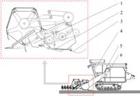
When the header is working, the height detection mechanism runs close to the ground under the pressure of the torsion spring and rotates with the ups and downs of the ground. The angle sensor rotates synchronously with the height detection mechanism. When the system detects the change in height of header from ground ΔH < 100 mm, the parallelogram structure of the mechanical profiling mechanism is used to perform mechanical profiling with the ups and downs of the ground. When the Change in height of header from ground ΔH ≥ 100 mm, the hydraulic cylinder is used to control the height of the header to ensure that the stubble height is always at the set value.
In Figure 2 the structure of the adaptive height adjustment system is shown. The hydraulic execution part and the height closed-loop control part of the header are controlled by programmable logic controller (PLC). The display module is a 7-inch LCD touch screen, which includes manual / automatic adjustment switch key and manual adjustment key.

The hydraulic actuator is composed of a double-acting hydraulic cylinder, a speed control valve, an electromagnetic reversing valve, a manual reversing valve and an overflow valve. The speed control valve is responsible for adjusting the lifting speed of the header to prevent the impact damage to the hydraulic cylinder caused by the fast action. The electromagnetic directional valve is used to control the expansion and contraction of the hydraulic cylinder, so as to realize the lifting operation of the header. The height closed-loop control part of the header is composed of PLC controller, solenoid valve, angle sensor, parallel-ogram mechanical profiling mechanism and arc detection mechanism. The height detection mechanism rotates with the fluctuation of the ground. The angle sensor converts the rotation into an electrical signal. The Fuzzy-PLC receives the signal from the angle sensor to judge the action of the hydraulic execution part. Because the header is wide, the single height detection mechanism cannot accurately perceive the height change of the whole header. Therefore, two height detection mechanisms arranged along the same straight line of the header longitudinal beam are designed to detect the height change of the header synchronously.
The mechanical profiling device shown in Figure 3 is composed of a parallelogram mechanical profiling mechanism and a height detection mechanism (Yu et al., 2019; Liang et al., 2022).
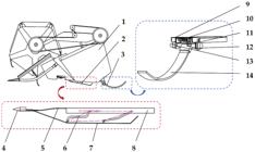
The parallelogram mechanical profiling mechanism is used to realize the passive mechanical pro-filing of the header. It is composed of a cutter, an elastic connecting plate, a towing plate and a towing plate connecting rod. The towing plate connecting rod is fixed on the vertical beam at the bottom of the header, and forms a parallelogram mechanism with the vertical beam and the towing plate at the bottom of the header. Limited by the overall structure of the header, the existing mechanical profiling height can only reach about 100 mm (Sun et al., 2006; Jin et al., 2019). When the header is working, the towing plate is always attached to the ground, and the fluctuation of the towing plate with the change of the terrain drives the synchronous fluctuation of the parallelogram mechanism, so as to realize the lifting and lowering of the parallelogram mechanical profiling mechanism, and then ensure the consistency of the stubble height.
The principle of the height detection mechanism is shown in Figure 4.

Through the analysis of the geometric relationship in Figure 4, the relationship between H0, H and θ0, θ at the two positions of (a) and (b) is obtained by Eq. 1:
where:
H0 - cutting height of the cutter in the initial position;
H - cutting height after ground height changes;
R - theoretical radius of the arc-shaped soil-engaging component;
θ0 - the angle between the rotation center and the fixed position of the arc-shaped soil-engaging component in the initial; and,
θ - the angle between the rotation center and the fixed position of the arc-shaped soil-engaging component after the header height changes.
The relationship between the ground height changes ΔH and the angle change of the arc-shaped soil-engaging component ∆θ is obtained by Eq. 2:
where:
Δθ - the change in the angle between the rotation center and the fixed position of the arc-shaped soil-engaging component; and,
ΔH - ground height changes.
The size of α and β depends on the geometric size and installation position of the hydraulic cylinder, and is a constant, this constant can be obtained by Eq. 3:
where:
α - the angle between T1 and T3; and,
β - the angle between T2 and T4.
The height change of the ground is obtained by Eq. 4:
where:
γ0 - the angle between T1 and T2 in the initial position; and,
γ - the angle between T1 and T2 after ground height changes.
The change of hydraulic cylinder elongation is obtained by Eq. 5:
where:
ΔT - the change of hydraulic cylinder elongation.
According to Eq. 4 and Eq. 5, the relationship between the cylinder variation ΔT and the height variation ΔH is obtained by Eq. 6:
According to Eq. 3 and Eq. 6, the relationship between the angle change ∆ θ of the arc-shaped soil-engaging component and the cylinder change ΔT is obtained by Eq. 7:
Through the change of the angle of the curved soil-engaging component, we can know the size of the height change ΔH of the current header.
When the height detection mechanism is working, considering the contact and friction between the arc-shaped soil-engaging component and the soil, in order to prevent the soil-engaging component from being worn and rusted, 304 stainless steels with a density of 7.93 × 10³ kg m-3 is selected as the material. In order to reduce the impact damage that may be caused to the soil-engaging component during the retreat of the harvester, the ground-touching parts adopt an overall arc structure design. According to the measurement results of the salt-alkali tolerant soybean varieties planted by the Yellow River Delta Intelligent Agricultural Machinery Equipment Industry, Shandong Province, the soybean pod height is between 75-300 mm. Therefore, the detection height of the arc-touching parts should exceed this range. Based on this, the theoretical radius R of the arc-shaped soil-engaging component is initially designed to be 250 mm, the angle θ between the two ends of the arc and the center of the circle is 90°, the width is 80 mm, and the height is 15mm to ensure that it can cover all measured pod heights.
The arc-shaped soil-engaging component always maintains close contact with the ground under the action of the torsion spring and accurately senses the height of the header from the ground, so the design of the torsion spring is particularly important. In order to determine the appropriate value range of the relevant parameters of the torsion spring, the force analysis of the working process of the height detection mechanism is carried out. As shown in Figure 5, when the header moves along the forward direction at a speed v, the overall force balance equation of the soil-engaging component is obtained by Eq. 8 and 9:
where:
FN1 - support force of the rotating shaft on the soil-engaging component, N;
M - torque applied by the torsion spring, N m;
G - weight of the soil contact component itself, N;
FN2 - support force of the ground, N;
f - friction force of the ground on the soil-engaging component, N;
lOA - horizontal distance from the gravity point to the rotation center O, m;
lOB - horizontal distance from the ground support force point to the rotation center O, m; and,
lOC - vertical distance from the friction force point to the rotation center O, m.

According to Eq. 9, when the size and material of the soil-engaging component is determined, its torque is closely related to the support force FN2 given by the ground. In actual working conditions, due to the uneven ground and the presence of obstacles such as soil blocks and weeds, the contact force FN2 on the soil-contacting component will change continuously. At this time, if the torque M of the torsion spring is too small, the soil-engaging component will jump and cannot maintain continuous contact with the ground, thus affecting the measurement accuracy of the angle sensor; on the contrary, if the torque M is too large, the soil-engaging component will wear due to excessive friction, shortening its service life.
In addition, the design of the torsion spring is also related to the elastic modulus E and yield strength of the torsion spring. Taking the three into consideration, the design calculation formula of the torsion spring can be obtained from Eq. 10 (Yuan et al., 2016).
where:
M - the torque applied by the torsion spring, N;
E - the elastic modulus, MPa;
d - the diameter of the torsion spring, mm;
α - the initial twist angle, ° ;
n - the number of torsion springs; and,
D - the diameter of the torsion spring, mm.
According to Eq.10, the torque value M of the torsion spring is the key parameter to determine the size of the torsion spring. In order to obtain the accurate parameters of the torque value M, the design of the torsion spring is completed (Zhu et al., 2022), and the detection requirements are realized. The multi-body dynamics simulation software ADAMS and the discrete element simulation software EDEM are used to perform MBD-DEM coupling simulation. (Wang et al., 2024).
A soil particle bed model was developed for saline-alkali soils from the Yellow River Delta Agricultural High-tech Zone. Based on measured soil particle size distribution, mass fractions, intrinsic soil parameters from literature, and terrain elevation variations, a 3000 mm × 400 mm × 500 mm undulating soil particle bed was created in SolidWorks. The saline-alkali soil particle model utilized spherical particles with 2 mm radius, employing the Hertz-Mindlin with JKR Cohesion contact model. Key parameters included a surface energy of 3.207 J m-², static friction coefficient of 0.55, and restitution coefficient of 0.36 between particles.The soil bed model was imported into EDEM, where 973,000 discrete element particles were generated to fill the structure (Figure 6B). The height detection mechanism was simplified into three components: rotating shaft, fixed sleeve, and soil-engaging component. Full-scale 3D models (.STEP format) were built in SolidWorks and imported into both Adams and EDEM for pre-simulation processing (Figure 6A) and the simulation parameters are shown in Table 1.

Multi-body dynamics (MBD) - Discrete element method (DEM) model simulation parameter setting table
In Adams, configure the motion parameters for the height detection mechanism by adding a fixed joint between the soil-engaging component and the fixed sleeve, a revolute joint between the soil-engaging component and the rotating shaft, and a contact pair between the rotating shaft and the ground (Li et al., 2020). In EDEM, define the material properties and component names for the height detection mechanism. Utilize an intermediate coupling file (.cosim) to link the components between Adams and EDEM, and execute the co-simulation by invoking the (.cosim) file through the Adams co-simulation module.
In the simulation test, set the target height of the height detection mechanism to 55 mm, and the forward speed of the height detection mechanism is taken as the main influencing factor. Four speed levels commonly used in soybean harvesters are selected: 1, 1.2, 1.5, 2 m s-1, and the simulation time is adjusted accordingly. The torque at the connection between the soil-contact component and the rotating shaft is monitored during operation at these speeds to determine the required torque for the balancing torsion spring.
To further optimize the torque value, set the forward speed of the height detection mechanism in Adams to 1.2 m s-1. A revolute joint is added between the rotating shaft and the fixed sleeve in the simulation model to simulate the torque applied by the torsion spring. The total simulation time is set to 2 seconds, and the torque values are 0 (no torque), 27, 54, and 108 N mm, respectively. The influence of torque on the walking performance of touchdown components is studied.
As shown in Figure 2, the adaptive height adjustment system is mainly composed of angle sensors, hydraulic cylinders, electromagnetic reversing valves, etc. Under the control of PLC, the dynamic response of each part of the device will affect the accuracy of the entire system model (Yang et al., 2008). Therefore, the response of each part should be fully considered when constructing the mathematical model.
The output and input of the angle sensor can be roughly regarded as a proportional link (Zhang et al., 2008). The transfer function G1(S) is obtained by Eq. 11:
where:
Ks - the gain coefficient of the sensor, V/°; and,
τs - the time constant of the sensor, which represents the dynamic response delay of the sensor, s; s is the Laplace operator.
The electromagnetic directional valve uses current I to control the on-off of the valve to control the inlet and outlet direction of the hydraulic oil, and realizes the expansion of the hydraulic cylinder to improve the header (Wu et al., 2008). The transfer function G2(S) is obtained by Eq. 12:
where:
Kv - the gain coefficient of the reversing valve, m/A;
τv - the time constant of the reversing valve, describing the response speed of the valve, s.
The control of double-acting hydraulic cylinder is mainly related to the change of pressure and the displacement of piston, and its transfer function G3(S) is obtained by Eq. 13:
where:
Kc - the gain coefficient of the hydraulic cylinder, which describes the proportional relationship between the pressure change in the hydraulic cylinder and the piston displacement, mm/MPa; and,
τc - time constant of the hydraulic cylinder, which describes the inertia of the hydraulic system and the fluid dynamics effect of the hydraulic oil, s.
According to Eq. 9, the relationship between the angle variation ∆ θ of the arc-shaped soil-engaging component and the elongation ∆ T of the hydraulic cylinder is known. Assuming that the relationship between them satisfies Eq. 14:
where:
Kθ - the conversion coefficient of hydraulic cylinder extension to header height.
The mathematical model of the height adjustment system based on the angle sensor detecting the height change Δθ to adjust the hydraulic cylinder extension ΔT is obtained by Eq. 15:
In order to effectively improve the response performance of the header adaptive height adjustment system, a PID controller is added to the header adjustment system. Its transfer function is obtained by Eq. 16:
Considering the complex mathematical model between the angle variation of this system and the hydraulic cylinder elongation, a fuzzy algorithm is introduced in the control process to further optimize the adaptive header height adjustment system, which can dynamically adjust the P, I, and D values of the controller.
As shown in Figure 7, the displacement deviation e and the displacement change rate of the hydraulic rod are taken as the input, and the values of ΔKp, ΔKi and ΔKd are obtained by the fuzzy algorithm. The control parameters Kp, Ki and Kd of the fuzzy PID are obtained by superimposing them with the values of the ordinary PID.

Combined with the actual working conditions of the hydraulic cylinder selected in this paper, the basic domain of the input variable deviation e and the deviation change rate of the fuzzy controller is defined as [-200,200] and [-2,2], and the fuzzy do-main is set as [-2,2]. The basic domains of the output variables ΔKp, ΔKi and ΔKd are [ -10,10], [ -0.2,0.2] and [-0.02,0.02], and the fuzzy domain is set to [-1,1]. The fuzzy values of the input and output language variables of the fuzzy controller are taken as [NB, NM, NS, ZE, PS, PM, PB], which represent negative large, negative medium, negative small, zero, positive small, positive medium and positive large respectively. The fuzzy control rules are formulated by introducing the actual control experience of experts as shown in Table 2 (Su et al., 2004); the input and output variables are represented by triangular membership functions, as shown in Figures 8A and 8B respectively.

Fuzzy-proportional-integral-derivative membership function for the input (A) and output (B) variables
This design uses Siemens S7-1200 PLC, as shown in Figure 9 for the hardware connection diagram of the system, using CODESYS to write the header height adjustment program (Geng et al., 2020), as shown in Figure 10 for the adaptive height adjustment system flow chart.


The system starts up. Firstly, the cutting height and the range of automatic adjustment ΔHauto are set. After pressing the start key, the profiling part collects the header signal. The analog signal is converted into a digital signal through the AD conversion circuit, and the height change ΔHL of the left header and the height change ΔHR of the right header are calculated according to Eq. 3. The average value of the two is taken to obtain ΔH, which is compared with ΔHauto. If |ΔH| is less than ΔHauto, it is automatically adjusted by the floating cutter of the header. If it is greater than ΔHauto, the positive and negative values of ΔH are judged. After PLC analysis and processing, the left and right positions of the solenoid valve are controlled. In order to control the hydraulic system, the elongation of the hydraulic cylinder is calculated by Eq. 6. In manual mode, PLC identifies the touch screen key signal, and controls the lifting of the header according to different key signals.
In order to verify the control performance of the header adaptive height adjustment system, a Matlab Simulink simulation model is established to simulate the adjustment system (Tian et al., 2003). The preset stubble height of the header is set to 55 mm, the simulation step is 200, and the simulation time is 2 seconds. The adaptive height adjustment system is simulated and analyzed in Matlab.
In order to test the performance, reliability, and control accuracy of the soybean header copying device and adaptive height adjustment system, soybean field harvesting was carried out in October 2024 in the saline alkali land of the Yellow River Delta Intelligent Agricultural Machinery Equipment Industry.
According to the requirements of the ‘ Soybean Combine Harvester Operation Quality ‘ standard (NY / T 738-2020), the harvesting test process was designed to verify the accuracy of the header adaptive height adjustment system. In this experiment, two methods were used to verify the accuracy of the system:
1. Accuracy test of different cutting heights at the same forward speed
Under the working condition of a forward speed of 1.5 m s-1, set the cutting height to three different levels: 40, 50, and 60 mm. Randomly select 20 sets of data for comparative analysis of cutting under each height condition, and evaluate the control accuracy of the system at different set heights.
2. Accuracy test of different forward speeds at the same cutting height
At a cutting height of 50 mm, three operating speed conditions of 1, 1.5, 2 m s-1 were selected, and 20 sets of cutting height data were randomly collected to analyze the impact of speed changes on control accuracy.
During each test, the harvester harvested a range of 20 m, and 20 stubble height samples were randomly selected for measurement. When measuring, the usage ruler is close to the ground to measure the stubble height to ensure the accuracy and consistency of the data.
The average stubble height X, the coefficient of variation of stubble height C.V and the sample variance σ2 were used as the evaluation indexes of field experiment, X can be calculated by Eq. 17; C.V can be calculated by formula Eq. 18; σ2 can be calculated by Eq. 19:
where:
Xi - the stubble height measured from the i-th time, mm;
X - the average stubble height, mm;
µ - the stubble height setting value, mm; is the sample variance; and,
n - the number of sample collection times.
According to the test methods, the three conditions of setting the cutting height to 40, 50, and 60 mm were tested under the working condition of the forward speed of 1.5 m s-1; at the same time, under the condition of setting the cutting height to 50 mm, the cutting height was tested and data was collected for three different working speeds of 1, 1.5, and 2 m s-1. The test results are shown in Table 3.
Results and Discussion
As shown in Figure 11, the average torque at the connection between the soil-engaging component and the rotating shaft during the operation of the height detection mechanism at different speeds is approximately 27 N mm, while the maximum torque reaches 584.5 N mm, indicating a significant disparity between the average and peak values. In real-world conditions, this manifests as severe, irregular, and abrupt shaking of the height detection mechanism when operating without the constraint of a torsion spring.

When the speed increases, the average torque at the connection rises from 25.84 N mm to 29.53 N mm, suggesting that the shaking intensifies with higher speeds (Figures 11A-C). At even higher speeds (Figure 11D), the abrupt torque fluctuations diminish, indicating that the height detection mechanism loses contact with the soil and only interacts with it during sudden changes in soil height, thereby generating torque (Jia et al., 2018).
To balance the torque at the connection between the soil-engaging component and the rotating shaft, a sufficiently large torsion spring should be added to lower the bottom of the height detection mechanism during operation to prevent the height detection mechanism from leaving the soil (Qu et al., 2021). The influence of adding different sizes of torque on the movement of soil-engaging parts is shown in Figure 12.

The influence of different torques on the movement of soil-engaging component when applying 0, 27, 54 and 108 N mm torque (A, B, C, D)
When the torque is not applied (Figure 12A), due to the lack of the constraint of the torsion spring, the soil-engaging component vibrate obviously in many places during the forward process. When a torque of 27 N mm is applied (Figure 12B), the jitter phenomenon gradually weakens with the application of torque. When the torque increases to 54 N mm (Figure 12C), the jitter phenomenon is significantly reduced, and only slight jitter occurs when the soil height changes suddenly. The peak value of jitter is less than 10mm, showing good stability. However, although continuing to increase the torque can further reduce the jitter effect (Figure 12D), a larger torque will increase the pressure and friction of the soil-engaging component on the soil, causing the subsidence of the soil-engaging component and the increase of friction resistance, which will make the height measurement error (Cui et al., 2007).
Therefore, the torque value should be selected as small as possible under the premise of ensuring the reduction of the jitter effect. From the (Figure 12C), it can be seen that when the torque increases to 54 N mm, the jitter phenomenon has been significantly reduced. Therefore, the 54 N · mm torque value is selected as the reference for the design of the torsion spring.
According to the design calculation formula of torsion spring (Equation 10), the design of torsion spring is also related to its material, wire diameter, middle diameter, number of turns and torsion angle. Among them, the wire diameter refers to the diameter of the steel wire that constitutes the torsion spring, which determines the stiffness and bearing capacity of the spring : the thicker wire diameter will make the spring more rigid and able to withstand greater loads, but it will also increase the weight and space ; the smaller wire diameter makes the spring softer and respond faster, but it may have lower bearing capacity and be susceptible to fatigue. The middle diameter refers to the average diameter of the helical line of the torsion spring. Its size not only reflects the overall size of the spring, but also is related to the torque transmission. The torsion angle represents the angle change of the torsion spring under loading or working conditions, that is, the maximum rotation angle that the spring can achieve. Usually, under the same material and size conditions, the torsion angle is inversely proportional to the number of effective turns, but the number of effective turns increases, the overall size of the torsion spring will increase; therefore, the size and installation position of the soil-engaging parts should be considered in the design. In addition, in order to ensure the service life of the torsion spring, the design of the torsion spring also needs to use reliable materials (Geng et al., 2020).
In summary, stainless steel is used as the production material of the torsion spring, and its elastic modulus is 2.06 × 10⁵ MPa ; in order to ensure that the torsion spring can be closely combined with the soil-engaging components, the force arm of the torsion spring is designed to be 75 mm, the middle diameter is 25 mm, the initial torsion angle is 180 °, the wire diameter is 1.5 mm, and the number of turns is 8.
As shown in Figure 13, when the stubble height is set to 55 mm with the proportional coefficient KP = 12, integral coefficient KI = 0.4, and differential coefficient KD = 0.03 in the regulation system, the response curves of the two control strategies generate two intersection points Q1 and Q2. At the first intersection Q1 (occurring before 0.2 s in simulation time), both curves have approached the set height, indicating that appropriate parameter settings enable rapid response speeds for both control strategies. However, after passing Q1, the PID-only control curve continues to rise beyond the set value, demonstrating that although the PID-only control height system responds quickly, it exhibits significant overshoot (exceeding the 55 mm setting). This excessive height could lead to missed cutting of low-podded soybean plants, thereby increasing harvest loss rates (Li et al., 2024).

At the second intersection Q2, fuzzy PID control system has reached its steady-state value, maintaining close proximity to the 55 mm setpoint without oscillatory tendencies over time. In contrast, the PID-only control curve continues to decline after Q2 and ultimately stabilizes below the target height. This performance discrepancy reveals that the PID-only control method produces substantial steady-state error, manifesting as actual stubble height lower than the present value. Such undershoot may induce soil scraping phenomena, potentially causing header blockage and compromising operational efficiency.
Table 3 shows the specific control performance data of the two control modes.
As shown in Table 3, the adjustment time of the height control system using fuzzy PID control is only 0.2 s, which is 1 s less than that of the height control system using PID control only, indicating that the response speed of the height control system using fuzzy PID control is faster; The overshoot of the height control system using only PID control is 0.56%, the steady-state error is 0.17 mm, and the maximum error is 0.48 mm, indicating that the stability and accuracy of the system are poor, and a large overshoot will occur in the control process, and it fails to reach the set height of 55mm when it is stable, while the overshoot of the height control system using fuzzy PID control is 0.56%, the steady-state error is 0.17 mm, and the maximum error is 0.48 mm, which is 5.14% lower than that of the height control system using only PID control, the steady-state error is 0.94 mm, and the maximum error is 1.49 mm, greatly improving the control accuracy of the system and reducing overshoot. The stability of the system is increased.
Zhang (2019) pointed out that the fuzzy PID controller is superior to the traditional PID controller in terms of rise time, overshoot, steady-state time and steady-state error when studying the profiling and crop height measurement methods of the harvester header, which is also consistent with the experimental results.
In summary, the test results show that the height control system using the fuzzy PID control designed in this paper has greatly improved the response time, overshoot, steady-state error and maximum error compared with the PID control method, and the control effect is good. It can meet the rapid design requirements of the adaptive height adjustment system of the header and ensure the consistency of the stubble height during cutting.
The accuracy test results of the adaptive height adjustment system for the header are shown in Table 4.
In order to more intuitively show the control effect of the header under the two test methods, the software will be used to plot the six test results under the two test methods into a scatter plot, as shown in Figure 14. The scatter points of the test results are distributed on the upper and lower sides of the set height (dotted line). The closer the distance to the dotted line, the closer the set height is, the higher the accuracy of the system.

Header control under different stubble setting heights (A) and different working speed (B)
Based on the first three data groups in Table 4, when the operating speed is 1.5 m s-1, the control performance of the system for set heights of 40, 50, and 60 mm is as follows: the mean actual cut stubble heights are 43.35, 53.65, and 63.30 mm, with deviations from the set heights of +3.35, +3.65, and +3.30 mm respectively, and the errors do not exceed 4 mm. This indicates that the system can accurately control the header height with high precision. Additionally, the coefficients of variation (C.V.) for the three groups are 0.05, 0.04, and 0.04, respectively, which are all relatively low values. This indicates that the actual data are well concentrated and that the system is stable. The variances (σ²) of the three groups are 5.61, 5.50, and 5.91 respectively, with values that are both similar and low, further proving that the system has strong anti-interference capabilities under different height settings.
From the last three data groups in Table 4, when the cut stubble height is set at 50 mm, the system’s performance under operating speeds of 1, 1.5, and 2 m s-1 is as follows: the mean actual cut stubble heights are 53.40, 53.20, and 53.20 mm, with deviations from the set value of +3.40, +3.20, and +3.20 mm respectively, and the errors remain stable. This indicates that the system can effectively counteract the interference caused by speed variations within the 1 - 2 m s-1 range. At the lower speed of 1 m s-1, both the coefficient of variation (C.V. = 0.04) and the variance (σ² = 4.93) are low, indicating good system stability; however, when the speed increases to 2m s-1, the coefficient of variation rises to 0.077, the variance increases to 16.80, and there are 5 samples with errors exceeding 10 mm. This is due to the increased inertia of the machine at high speeds combined with the interference from uneven ground, which leads to a slight delay in the system response. Nonetheless, all sample errors remain within ±10 mm, verifying that the system can still meet the basic operational requirements in the 1-2m s-1 speed range (Wei et al., 2017; Zhao., 2022).
Zhang (2019) conducted field experiments by setting the harvester header heights at 200 and 250 mm and measuring the control errors under both PID control and fuzzy PID control. The results indicate that, under PID control, most control errors were within 20 mm with mean values of 5 and 3 mm, respectively, while under fuzzy adaptive PID control, most errors were within 15 mm with mean values of 2 and 1 mm. The error was reduced by 23%, demonstrating that the fuzzy PID control strategy is more effective.
Figures 14A and B show that the actual measured cut stubble heights are mostly slightly higher than the set heights, possibly due to zero drift in the angular sensor caused by repeated testing. This issue can be addressed by re-zeroing the sensor before operation to ensure the system’s long-term stability (Zhang et al., 2004).
In summary, the experimental data indicate that under normal conditions (1.5 m s-1 speed and 40 - 60 mm height), the system’s accuracy and stability are significantly better than those of traditional methods; although stability decreases at a high speed of 2 m s-1, it still meets operational requirements. This system provides a reliable technical foundation for adaptive height control in soybean harvesters, and its high-speed performance can be further enhanced by optimizing its dynamic response in future developments.
Conclusions
-
It was designed a header height detection mechanism, established mathematical relationships between header height, rotation angle of the curved soil-engaging component, and hydraulic cylinder extension.
-
It was developed an adaptive header height adjustment system incorporating hydraulic actuation and closed-loop height control. A system mathematical model was built and implemented a Fuzzy-PID controller.
-
Across varying operating speeds and stubble height settings, average height deviations remained < 4 mm, stubble height coefficient of variation (CV) stayed < 0.08, and control errors were confined to 10 mm, confirming the system’s high precision and operational stability.
Literature Cited
-
Carreira, V. dos S.; Aleixo, E. V.; Ribeiro, N. M.; Santos, J. do N.; Silva, R. P. da. A systematic and meta-analytical review of soybean mechanized harvesting in South America. Revista Brasileira de Engenharia Agrícola e Ambiental, v.28, e265804, 2024. https://doi.org/10.1590/1807-1929/agriambi.v28n1e265804
» https://doi.org/10.1590/1807-1929/agriambi.v28n1e265804 -
Cui, Z. R.; Li, J. Q.; Liu, Q. P. Experiment of soil drag reduction rate and dynamic observation of interface on concave surface. Journal of Agricultural Machinery, v.2, p.83-86, 2007. https://doi.org/10.3969/j.issn.1000-1298.2007.02.022
» https://doi.org/10.3969/j.issn.1000-1298.2007.02.022 -
Geng, A. J.; Zhang, M.; Zhang, J.; Zhang, Z. L.; Gao, A.; Zheng, J. L. Design and experiment of automatic control system for header height of corn harvester. Journal of Agricultural Machinery , v.2, p.118-125, 2020. https://doi.org/10.6041/j.issn.1000-1298.2020.S2.014
» https://doi.org/10.6041/j.issn.1000-1298.2020.S2.014 -
Jia, H. L.; Wang, W. P.; Chen, Z.; Zhuang, J.; Wang, W. J.; Liu, H. L. Real time measurement method for the ballast pressure of profiling elastic compaction roll based on soil firmness. Journal of Jilin University, v.48, p.1169-1175, 2018. https://doi.org/10.13229/j.cnki.jdxbgxb20170351
» https://doi.org/10.13229/j.cnki.jdxbgxb20170351 -
Jin, C. Q.; Guo, F. Q.; Xu, J. S.; Li, Q. L.; Chen, M.; Li, J.J.; Yin, X. Optimization of soybean combine harvester operating parameters. Journal of Agricultural Engineering, v.13, p.10-22, 2019. https://doi.org/10.11975/j.issn.1002-6819.2019.13.002
» https://doi.org/10.11975/j.issn.1002-6819.2019.13.002 -
Jin, C. Q.; Liu, G. W.; Ni, Y. L.; Yang, T. X.; Wang, T. G.; Qi, Y. D. Design and experiment of profiling mechanism of combine harvester header based on MBD-DEM coupling. Journal of Agricultural Engineering , v.2, p.1-10, 2022. https://link.cnki.net/doi/10.13733/j.jcam.issn.2095-5553.2019.12.04
» https://link.cnki.net/doi/10.13733/j.jcam.issn.2095-5553.2019.12.04 -
Lambrecht, D. M.; Lúcio, A. D.; Martin, T. N.; Feldmann, A. B. S.; Amaral, R. P.; Buligon, I. de O.; Tolfo, T. de C.; Diel, M. I. Sampling intensity and size to evaluate harvest losses in soybean crops. Revista Brasileira de Engenharia Agrícola e Ambiental , v.27, p.593-599, 2023. https://doi.org/10.1590/1807-1929/agriambi.v27n8p593-599
» https://doi.org/10.1590/1807-1929/agriambi.v27n8p593-599 -
Li, H. T.; Wu, C. Y.; Mu, L.; Guan, Z. H.; Jiang, T. The formation mechanism of laying angle of vertical rape windrower based on ANSYS-ADAMS. Journal of Agricultural Engineering , v.14, p.96-105, 2020. https://doi.org/10.11975/j.issn.1002-6819.2020.14.012
» https://doi.org/10.11975/j.issn.1002-6819.2020.14.012 -
Li, Z. R.; Xu, L. Z.; Xu, X. Q.; Xu, L.; Chai, X. Y. Design and simulation of mechanical-hydraulic combined soybean header profiling device. Agricultural Mechanization Research, v.5, p.60-65, 2024. https://link.cnki.net/doi/10.13427/j.cnki.njyi.2024.05.030
» https://link.cnki.net/doi/10.13427/j.cnki.njyi.2024.05.030 -
Liang, D.; Zhang, Z. J.; Chang, B. Y.; Li, L.; Qi, Y. Research on SCARA Parallel Mechanism with Double Parallel Quadrilateral Branches. Journal of Agricultural Machinery , v.53, p.422-434, 2022. https://doi.org/10.6041/j.issn.1000-1298.2022.07.046
» https://doi.org/10.6041/j.issn.1000-1298.2022.07.046 -
Liu, G. W.; Ni, Y. L.; Yang, T. X.; Qi, Y. D.; Jin, C. Q. Design and experiment of automatic control system for header height of soybean harvester. Chinese Journal of Agricultural Machinery Chemistry, v.06, p.155-160, 2023. https://link.cnki.net/doi/10.13733/j.jcam.issn.2095-5553.2023.06.022
» https://link.cnki.net/doi/10.13733/j.jcam.issn.2095-5553.2023.06.022 -
Paixão, C. S. S.; Chrispin, C. P.; Silva, R. P. da; Girio, L. A. S.; Voltarelli, M. A. Physical and physiological quality of soybean seeds at three speeds of the harvester. Revista Brasileira de Engenharia Agrícola e Ambiental , v.21, p.214-218, 2017. https://doi.org/10.1590/1807-1929/agriambi.v21n3p214-218
» https://doi.org/10.1590/1807-1929/agriambi.v21n3p214-218 -
Qu, X. X.; Cao, D. X.; Zhang, S. Design and research of a kind of torsion spring flexible joint with variable stiffness. Journal of Mechanical Engineering, v.57, p.114-123, 2021. https://link.cnki.net/urlid/11.2187.TH.20210608.1031.014
» https://link.cnki.net/urlid/11.2187.TH.20210608.1031.014 -
Su, M.; Chen, L. J; Lin, H. Fuzzy PID Control and Its MATLAB Simulation. Modern Machinery, v.04, p.51-55, 2004. https://doi.org/10.3969/j.issn.1002-6886.2004.04.008
» https://doi.org/10.3969/j.issn.1002-6886.2004.04.008 -
Sun, G. Q. 218 Technology of Harvesting Soybean by Flexible Cutting Table. Agricultural Mechanization in Xinjiang, v.3, p.59-60, 2006. https://doi.org/10.3969/j.issn.1007-7782.2006.03.036
» https://doi.org/10.3969/j.issn.1007-7782.2006.03.036 -
Tian, S. H.; Jiang, L. J. Research on a parameter self-tuning fuzzy PID controller. Electrical Drive Automation, v.25, p.28-30, 2003. https://doi.org/10.3969/j.issn.1005-7277.2003.06.009
» https://doi.org/10.3969/j.issn.1005-7277.2003.06.009 -
Wang, D. W.; Lu, T.; Zhao, Z.; Shang, S. Q.; Zheng, S.; Liu, J. Calibration method of discrete element simulation parameters of cultivated soil in coastal saline-alkali land. Journal of Agricultural Machinery , v.11, p.240-249, 2024. https://link.cnki.net/urlid/11.1964.S.20240903.1531.002
» https://link.cnki.net/urlid/11.1964.S.20240903.1531.002 -
Wang, R. S.; Kang, Y. H.; Wan, S. Q.; Sun, J. X. Effects of water regulation on the content and distribution of salt and nutrients in saline-alkali soil. Journal of Agricultural Engineering , v.30, p.96-104, 2014. https://doi.org/10.3969/j.issn.1002-6819.2014.14.013
» https://doi.org/10.3969/j.issn.1002-6819.2014.14.013 -
Wang, S.; Li, B.; Chen, S.; Tang, Z.; Zhou, W.; Guo, X. Design and performance test of soybean profiling header suitable for harvesting bottom pods on film. Agriculture, v.14, e1058, 2024. https://doi.org/10.3390/agriculture14071058
» https://doi.org/10.3390/agriculture14071058 -
Wei, L. G.; Che, Y.; Wang, F. Z.; Li, W. Design and experiment of ground contour control system for combine harvester cutting platform. Agricultural Mechanization Research , v.39, p.150-154, 2017. https://doi.org/10.13427/j.cnki.njyi.2017.05.028
» https://doi.org/10.13427/j.cnki.njyi.2017.05.028 -
Wu, G. X. Simulation of valve-controlled hydraulic cylinder hydraulic servo system based on AMESim. Machinery, v.1, p.28-30, 2008. https://doi.org/10.3969/j.issn.1006-0316.2008.01.011
» https://doi.org/10.3969/j.issn.1006-0316.2008.01.011 -
Yang, S. M.; Yang, Q.; Yang, Y. H.; Yang, S. C. Design of header height control system based on ultrasonic sensor. Agricultural Mechanization Research , v.03, p.134-156, 2008. https://doi.org/10.3969/j.issn.1003-188X.2008.03.041
» https://doi.org/10.3969/j.issn.1003-188X.2008.03.041 -
Yu, F.; Xu, X.; Luo, Y. Z. Rotating opening and closing plate structure based on parallelogram ring chain. Journal of Zhejiang University (Engineering Edition), v.53, p.1040-1046, 2019. https://doi.org/33.1245.T.20190507.1246.004
» https://doi.org/33.1245.T.20190507.1246.004 -
Yuan, L. H.; Xie, X.; Shi, J. Z. Virtual design and simulation analysis of soybean harvesting machinery cutting mechanism. Agricultural Mechanization Research , v.38, p.76-80, 2016. https://doi.org/10.3969/j.issn.1003-188X.2016.11.014
» https://doi.org/10.3969/j.issn.1003-188X.2016.11.014 -
Zhang, C. Research on the method of profiling and crop altimetry of harvester header. Master’s Thesis of Inner Southeast University, 2019. https://doi.org/10.27014/d.cnki.gdnau.2019.002851
» https://doi.org/10.27014/d.cnki.gdnau.2019.002851 -
Zhang, C. F.; Luo, J. R. Discussion on software method to remove zero drift. Computer Measurement and Control, v.7, p.684-686, 2004. https://doi.org/10.16526/j.cnki.11-4762/tp.2004.07.028
» https://doi.org/10.16526/j.cnki.11-4762/tp.2004.07.028 -
Zhang, K.; Yang, Q. H.; Li, B.; Li, H. Development of non-contact angle sensor based on Hall device. Journal of Sensing Technology, v.6, p.981-984, 2008. https://doi.org/10.3969/j.issn.1004-1699.2008.06.018
» https://doi.org/10.3969/j.issn.1004-1699.2008.06.018 -
Zhang, Z.; Wang, L.; Han, K. L.; Chi, R. J. Research on adaptive control system for corn harvesting based on disturbance observation. Journal of Agricultural Machinery , v.55, p.85-94, 2024. https://doi.org/10.6041/j.issn.1000-1298.2024.S2.009
» https://doi.org/10.6041/j.issn.1000-1298.2024.S2.009 -
Zhao, Y. Research on Automatic Monitoring System for Combine Harvester. Use and Maintenance of Agricultural Machinery, v.4, p.59-61, 2022. https://doi.org/110.14031/j.cnki.njwx.2022.04.018
» https://doi.org/110.14031/j.cnki.njwx.2022.04.018 -
Zhu, H. B.; Wu, X. A.; Bai, L. Z.; Qian, C.; Zhao, H. R.; Li, H. Development of biaxial stubble-breaking no-tillage device for rice stubble field based on EDEM-ADAMS simulation. Journal of Agricultural Engineering , v.19, p.10-22, 2022. https://doi.org/10.11975/j.issn.1002-6819.2022.19.002
» https://doi.org/10.11975/j.issn.1002-6819.2022.19.002
Financing statement
This study has no supplementary research data.

 1 - Harvester header; 2 - Parallelogram mechanical profiling mechanism; 3 - Height detection mechanism; 4 - PLC control unit; 5 - Electromagnetic valve; 6 - Hydraulic cylinder

 1 - Cutter shell; 2 - Parallelogram mechanical profiling mechanism; 3 - Height detection mechanism; 4 - Cutter; 5 - Elastic connecting plate; 6 - Tow plate connecting rod; 7 - Tow plate; 8 - Vertical beam; 9 - Fixed plate; 10 - Torsion spring; 11 - Angle sensor; 12 - Soil-engaging component fixed sleeve; 13 - Rotary shaft of soil-engaging component; 14 - Soil-engaging component
 A. Initial position; B. The position after ground height changesT1 - The line from the installation point C1 of the header hydraulic cylinder to the rotation center point C3 of the header lifting arm; T2 - The line from the installation point C2 of the hydraulic cylinder chassis to the rotation center point C3 of the header lifting arm; T3 -The line from the cutter position C0 to the center point C3 of the lifting arm of the header; T4 - The vertical line from the center point of the lifting arm of the header C3 to the ground C4; T0 - The length of the cylinder in the initial position; T - The length of the cylinder after ground height changes;
 v - the forward speed of the header
 A. Height detection mechanism model in Adams; B. Soil particle bed model in EDEM

 A. e, ec membership function; B. ΔKp ΔKi ΔKd membership functione - Variable deviation; ec - The deviation change rate; ΔKp - Correction amount of Kp; ΔKi - Correction amount of Kd; ΔKd - Correction amount of Kd
 V - Voltage; A - Ampere; RXD - Receive external data; TXD - Transmit Data; HMI - Human Machine Interface; RS232 - Recommended Standard 232; VCC - Volt Current Condenser; GND - Ground
 ΔHL - Left side header height variation;HR - Right side header height variation;ΔHauto - Automatic adjustable height range
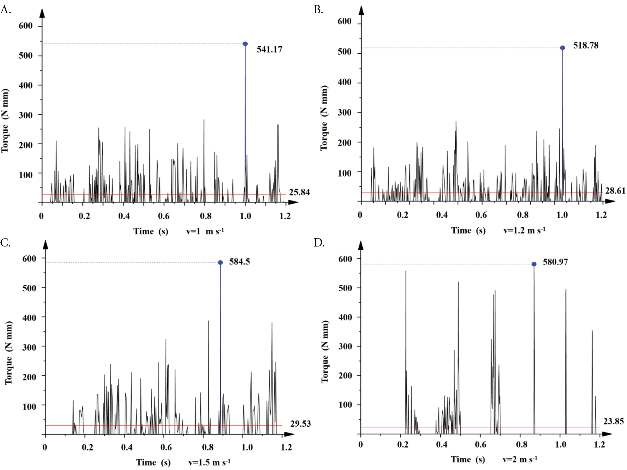 Torque variation curve of the torque at the connection between the soil contact component and the rotating shaft at 1 m s-1 (A),Torque variation curve of the torque at the connection between the soil contact component and the rotating shaft at 1.2 m s-1 (B), Torque variation curve of the torque at the connection between the soil contact component and the rotating shaft at 1.5 m s-1 (C), Torque variation curve of the torque at the connection between the soil contact component and the rotating shaft at 2 m s-1 (D)

 Red line - Step response curve of traditional Proportional-Integral-Derivative controller; Blue line - Step response curve of fuzzy Proportional-Integral-Derivative controller; Q1 - The first intersection of the two response curves; Q2 - The second intersection of the two response curves
