Plasma Deposition of Ti-C Based Coating on AISI 420 Steel Using Titanium Cathodic Cage and Graphite Lid
Abstract
This work investigates the plasma deposition of Ti-C based coatings on AISI 420 steel using a cathodic cage technique with titanium and graphite components. The study examines two treatment conditions: cathodic potential and floating potential samples, with the objective of evaluating their influence on the coating properties. The results indicate that the cathodic potential treatment results in the formation of thicker coatings with enhanced microhardness, thereby improving wear resistance. Although both treatments demonstrated satisfactory wear resistance, they negatively impacted the corrosion resistance of the steel. X-ray diffraction analysis revealed the formation of TiC, Fe3C, Cr7C3 and Cr23C6 phases in the treated samples, which contribute to the improved microhardness and wear resistance. Wear tests confirmed reduced wear volume in the treated samples. The cathodic potential treatment exhibited greater microhardness and an extensive carburized layer, but the corrosion and wear resistance were similar in both conditions.
Keywords:
Carbides; Cathodic Cage; Plasma Deposition; Titanium
1. Introduction
Transition metal carbides are widely used as coatings in applications requiring exceptional surface properties. These materials exhibit high hardness, wear resistance, and good chemical stability1-3. Among these carbides, titanium carbide is particularly notable; it is widely reported in the literature as a means of enhancing wear resistance in various materials, especially steels4-6.
The deposition of carbide coatings is often carried out using techniques such as chemical vapor deposition (CVD)7, physical vapor deposition (PVD)8, and thermo-reactive diffusion treatment (TRD)6. These approaches aim to increase wear resistance and surface hardness. However, the hard coating (TiC) obtained by CVD and PVD generally exhibits poor adhesion to the substrate9, and the application of TRD treatments is limited to high temperatures and high-carbon steels.
The cathodic cage plasma deposition (CCPD) technique is extensively reported in the literature as a method for improving the properties of various materials, especially steels, through the deposition of a variety of coatings based on niobium10, vanadium11, copper12, molybdenum13, zinc14 and titanium15. The technique enables the deposition of coatings with excellent adhesion to various substrates, with treatments at low temperatures and short durations.
An essential parameter for plasma treatments is the sample potential, as it significantly influences both the composition of the deposited layer and the surface morphology. Variations in potential can alter the dynamics of ion bombardment and energy transfer, which in turn affects the thickness, hardness, and uniformity of the coating13,16-18. In this study, titanium carbide (TiC) coatings were synthesized on a steel substrate (AISI 420) at a temperature of 400 °C using the CCPD technique under two different treatment conditions (cathodic potential and floating potential).
2. Methodology
2.1. Sample preparation and treatment
Samples of AISI 420 martensitic stainless steel with dimensions of 0.2 cm in thickness and 2 cm in diameter, and a composition (wt.%) of 12.64 Cr, 0.22 C, 0.32 Mn, 0.03 S, 0.33 Ni, 0.44 Si, 0.03 P, and Fe in balance, supplied by Villares Metals S/A, were metallographically prepared using SiC sandpaper up to 1200 mesh and polished with suspended alumina (0.3 μm).
The treatment configuration adopted is shown in Figure 1. The cage was manufactured from a titanium plate with 8 mm holes evenly distributed, with a distance of 9.2 mm between adjacent holes, acting as a source of titanium atoms, while the graphite lid serves as a source of carbon.

In this work, the samples were treated at cathodic potential (samples placed directly on the cathodic sample holder) and at floating potential (samples placed on an insulating alumina disk). The treatment was conducted at a temperature of 400 °C for a duration of 4 hours, with a DC voltage of 600 V and a current of 0.55 A. The atmosphere used was argon only, with a flow rate of 0.83 cm3/s (equivalent to 50 cm3/min) and a pressure of 100 Pa.
2.2. Characterization
The XRD analysis was carried using a SHIMADZU XRD 6000 diffractometer at a voltage of 40 kV, a current of 30 mA, a scan speed of 1°/min, in a scan range (2θ) of 35° to 85°. SEM images were obtained using an FEI-Company Quanta FEG 250 microscope. Superficial hardness was measured by Vickers microhardness testing using an INSIZE ISH-TDV 1000 microhardness tester; 5 indentations were performed on each sample with 50 gf for 15 seconds.
The fixed-sphere micro-abrasive wear test was performed using a 52100 steel ball with a diameter of 25.4 mm, a normal load of 8 N and a rotation frequency of 40 Hz. This ball-sample wear test generates a hemispherical impression (cap) on the surface of the worn sample. The equipment used is described in Sampaio et al.15. The samples were analyzed with a Wireless microscope equipped with a digital camera, and the diameter of the caps formed on the sample surface was measured using the equipment's Measurement software. This value was then used to calculate the worn volume of each material.
The wear volume (V) was determined using Equation 1, where R represents the radius of the steel ball, and b indicates the diameter of the crater19.
The corrosion tests were carried out in an electrolytic cell with three electrodes, using a 3.5% NaCl solution as the corrosive environment. The samples were used as the working electrode, while the counter electrode was a platinum foil, and the reference electrode was Ag/AgCl in a saturated KCl solution. The polarization curves were obtained by starting the scan 250 mV below the open circuit potential (OCP), at a rate of 1 mV s-1, until reaching a rate of 1 mA cm-2. The measurements were performed in triplicate to verify the reproducibility of the test. The OCP measurements were taken before the polarization curves, with monitoring lasting 1 hour.
3. Results and Discussion
Figure 2 shows the X-ray patterns of the treated samples. It can be observed that the cathodic cage treatment resulted in the formation of phases such as TiC, Fe3C, Cr23C6 and Cr7C3 in the samples treated at both cathodic and floating potentials20-22. The phases formed are the result of the sputtering of the titanium cage and graphite lid (and the sample in the cathodic potential treatment), as well as the precipitation of phases due to carbon diffusion. The Base sample shows only alpha iron (body-centered cubic), as indicated in the Figure 2 as α. The Cathodic sample shows the formation of more intense peaks of these phases, especially the intense TiC peak, indicating more extensive formation of these phases in the treatment at cathodic potential.

The carbon diffusion zones of the treated samples are shown in the micrographs in Figure 3. It is possible to observe the formation of an extensive diffusion zone in the sample at cathodic potential (39.4 ± 0.9 μm), while in the sample treated at floating potential the cemented zone is difficult to distinguish and can only be seen by electron microscopy (Figure 4).


Figure 4 shows the SEM images of the cross-section of the samples treated at floating and cathodic potential, which exhibit a compound layer and a carbon diffusion zone (cemented zone). The thickness of the compound layer of the samples treated at floating and cathodic potential was 1.9±0.1 and 4.6±0.6 μm, respectively.
The SEM images also show a large number of precipitates, which may be associated with the precipitation of Cr23C6 and Cr7C3 due to carbon diffusion and the formation of the cemented layer. This hypothesis is corroborated by the X-ray patterns in Figure 2.
The surface microhardness of the untreated and treated samples is presented in Figure 5. It can be observed that the treated samples had higher microhardness than the untreated sample, due to the formation of a higher amount of carbide phases. The sample treated at cathodic potential showed greater hardness, as there was a higher intensity of formation of carbide phases (Figure 2) as well as a greater layer thickness (Figure 3). There was also a greater dispersion of microhardness values in this sample, which can be explained by the edge effect, since the sample was in contact with the cathode and not isolated like the floating potential sample23-25. The lower hardness of the Floating sample compared to the Cathodic sample is associated with the smaller cemented zone.

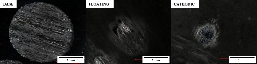
The wear resistance of the TiC coatings was evaluated by microabrasive wear, and the wear tracks were analyzed by optical microscopy, as shown in Figure 6. The untreated sample (Base) shows a large wear cap, with the surface exhibiting severe damage, the presence of grooves, and intense plastic deformation, with a wear volume of 115.9 x10⁻³ mm3 at the end of the test (Figure 7). The predominant wear mechanism for the untreated sample was abrasive, evidenced by the deep grooves and severe wear. In contrast, the treated samples showed small wear scars; the Floating sample had the lowest wear volume of all the samples with a volume of 2.21 x10⁻³ mm3, representing a 98% reduction in wear volume, while the sample treated with cathodic potential showed a 96% reduction in wear volume (4.35x 10⁻³ mm3). For the treated samples, low-grade galling and light scoring were the primary wear mechanisms, reflecting the increased surface hardness due to the TiC coating. The low wear volume may be associated with the presence of TiC and chromium carbides (Cr23C6 and Cr7C3)21,22.


The coefficient of friction monitored during the wear test is shown in Figure 8. It can be seen that there was an increase in the coefficient of friction due to the treatments. Additionally, the treated samples showed nearly identical values for the coefficient of friction, which can be attributed to the similar composition of the coatings26 (Figure 2).

Figure 9 shows the OCP monitoring of the samples over a period of 60 minutes. The potential of the Floating sample starts with values similar to those of the untreated sample but drops considerably in the first 20 minutes until it approaches the potential of the Cathodic sample. After approximately 40 minutes, the potential of all the samples tends to stabilize.

Figure 10 shows the potentiodynamic behavior of the untreated and treated samples in the polarization curves. In general, the curves of the treated samples are more anodic than the base material, with the untreated sample showing the highest corrosion potential, -0.42 V and a corrosion current density of 5.98x10⁻⁷ A cm-2. The treated samples exhibited lower corrosion resistance, with lower corrosion potentials (Table 1). The decrease in the corrosion resistance of the treated samples is due to the formation of chromium carbides (Cr7C3 and Cr23C6), which consume the chromium present in the iron-based solid solution. This deterioration in corrosion resistance is common in physical vapor deposition (PVD) and thermochemical treatments15,27,28. Morphological aspects and adhesion to the substrate are also factors that can influence the corrosion resistance of alloys treated by surface engineering techniques29,30.

4. Conclusions
In this article, the cathodic cage plasma deposition technique was applied using a configuration with the cage made of titanium and the lid of graphite, with the aim of depositing Ti-C based coatings. Two treatments were studied: cathodic and floating potential. The treatment carried out with the sample at cathodic potential produced layers with greater thickness and microhardness; however, in both conditions, the coatings showed good wear resistance. The corrosion analyses, however, indicated that the treatments were detrimental to the corrosion resistance of the AISI 420 steel, suggesting that the application of treatments to stainless steels should focus on promoting an increase in wear resistance, accepting some loss in corrosion resistance. Additionally, the coefficient of friction of the samples treated at cathodic potential showed greater instability compared to the samples treated at floating potential. The wear of the samples treated at cathodic potential exhibited a reduction of 96%, while the samples treated at floating potential showed a wear reduction of 98%.
5. Acknowledgments
The authors would like to thank the Física dos Materiais FisMat-UFPI/MCTI/FINEP and Núcleo Interdisciplinar de Materiais Avançados-LIMAV-UFPI/MCTI/FINEP for the support. This study was financed in part by the Coordenação de Aperfeiçoamento de Pessoal de Nível Superior – Brasil (CAPES) – Finance Code 001, and Conselho Nacional de Desenvolvimento Científico e Tecnológico (CNPq), proc. n° 314034/2023–4.
6. References
-
1 Krellin AP, Milan JCG, Costa CE, Almeida EAS, Galiotto A. Sliding wear behavior of niobium cardibe coated AISI 52100 bearing steel. Tecnol Metal Mater Min. 2017;14(2):133-40. http://doi.org/10.4322/2176-1523.1141
» http://doi.org/10.4322/2176-1523.1141 -
2 Cai X, Xu Y. Microstructure, friction and wear of NbC coatings on a Fe substrate fabricated via an in situ reaction. Surf Coat Tech. 2017;322:202-10. http://doi.org/10.1016/j.surfcoat.2017.05.046
» http://doi.org/10.1016/j.surfcoat.2017.05.046 -
3 Castillejo FE, Marulanda DM, Olaya JJ, Alfonso JE. Wear and corrosion resistance of niobium-chromium carbide coatings on AISI D2 produced through TRD. Surf Coat Tech. 2014;254:104-11. http://doi.org/10.1016/j.surfcoat.2014.05.069
» http://doi.org/10.1016/j.surfcoat.2014.05.069 -
4 Kurt B, Günen A, Kanca Y, Koç V, Gök MS, Kırar E, et al. Properties and tribologic behavior of titanium carbide coatings on AISI D2 steel deposited by thermoreactive diffusion. J Miner Met Mater Soc. 2018;70(11):2650-9. http://doi.org/10.1007/s11837-018-3108-5
» http://doi.org/10.1007/s11837-018-3108-5 -
5 Larhlimi H, Ghailane A, Makha M, Alami J. Magnetron sputtered titanium carbide-based coatings: a review of science and technology. Vacuum. 2022;197:110853. http://doi.org/10.1016/j.vacuum.2021.110853
» http://doi.org/10.1016/j.vacuum.2021.110853 -
6 Zhang J, Li S, Lu C, Sun C, Pu S, Xue Q, et al. Anti-wear titanium carbide coating on low-carbon steel by thermo-reactive diffusion. Surf Coat Tech. 2019;364:265-72. http://doi.org/10.1016/j.surfcoat.2019.02.085
» http://doi.org/10.1016/j.surfcoat.2019.02.085 -
7 Wang SL, Jiang N. Tribological performance and behaviour of CVD TiC/TiCN/TiN multilayer coating at elevated temperature. Surf Eng. 2021;37(1):1-11. http://doi.org/10.1080/02670844.2020.1807813
» http://doi.org/10.1080/02670844.2020.1807813 -
8 Restrepo E, Benavides V, Devia A, Olarte S, Arroyave M, Arango YC. Study of multilayer coatings of Ti/TiN/TiC produced by pulsed arc discharge. Braz J Phys. 2004;34(4b):1748-51. http://doi.org/10.1590/S0103-97332004000800043
» http://doi.org/10.1590/S0103-97332004000800043 -
9 Nishimoto A, Nishi C. Carbide layer coating on titanium by spark plasma sintering technique. Surf Coat Tech. 2018;353:324-8. http://doi.org/10.1016/j.surfcoat.2018.08.092
» http://doi.org/10.1016/j.surfcoat.2018.08.092 -
10 Naeem M, Raja FQ, Nolêto BJS, Serra PLC, Costa THC, Díaz-Guillén JC, et al. Surface modification of AISI-420 steel by cathodic cage plasma niobium nitride deposition. Mater Sci Technol. 2024;40(10):731-42. http://doi.org/10.1177/02670836231222845
» http://doi.org/10.1177/02670836231222845 -
11 Filho MVM, Naeem M, Monção RM, Díaz-Guillén JC, Hdz-García HM, Costa THC, et al. Improved mechanical and wear properties of AISI-420 steel by cathodic cage plasma vanadium nitride deposition. Phys Scr. 2023;98(11):115602. http://doi.org/10.1088/1402-4896/acfc87
» http://doi.org/10.1088/1402-4896/acfc87 -
12 Fernades F, Filho ER, Souza I, Nascimento I, Sousa R, Almeida E, et al. Novel synthesis of copper oxide on fabric samples by cathodic cage plasma deposition. Polym Adv Technol. 2020;31(3):520-6. http://doi.org/10.1002/pat.4792
» http://doi.org/10.1002/pat.4792 -
13 Naeem M, Fortaleza VC, Serra PLC, Lima CL, Costa THC, Sousa RRM, et al. Synthesis of molybdenum oxide on AISI-316 steel using cathodic cage plasma deposition at cathodic and floating potential. Surf Coat Tech. 2021;406:126650. http://doi.org/10.1016/j.surfcoat.2020.126650
» http://doi.org/10.1016/j.surfcoat.2020.126650 -
14 Junior WN, Naeem M, Costa THC, Díaz-Guillén JC, Díaz-Guillén MR, Iqbal J, et al. Surface modification of AISI-304 steel by ZnO synthesis using cathodic cage plasma deposition. Mater Res Express. 2021;8(9):096403. http://doi.org/10.1088/2053-1591/ac2443
» http://doi.org/10.1088/2053-1591/ac2443 -
15 Sampaio WRV, Serra PLC, Monção RM, de Sousa EM, Silva LGL, da Silva FLF, et al. Influence of using different titanium cathodic cage plasma deposition configurations on the mechanical, tribological, and corrosion properties of AISI 304 stainless steel. Surf Coat Tech. 2023;475:130149. http://doi.org/10.1016/j.surfcoat.2023.130149
» http://doi.org/10.1016/j.surfcoat.2023.130149 -
16 Li Y, Bi Y, Zhang M, Zhang S, Gao X, Zhang Z, et al. Hollow cathodic plasma source nitriding of AISI 4140 steel. Surf Eng. 2021;37(3):351-9. http://doi.org/10.1080/02670844.2020.1758012
» http://doi.org/10.1080/02670844.2020.1758012 -
17 Li Y, He Y, Xiu JJ, Wang W, Zhu YJ, Hu B. Wear and corrosion properties of AISI 420 martensitic stainless steel treated by active screen plasma nitriding. Surf Coat Tech. 2017;329:184-92. http://doi.org/10.1016/j.surfcoat.2017.09.021
» http://doi.org/10.1016/j.surfcoat.2017.09.021 -
18 Brito MCS, Nôleto BJS, Silva LP, Monção RM, Pereira JC, Queiroz MGO, et al. Study of the properties of iron and vanadium nitride coatings by CCPD on 1080 steel. Mater Res. 2024;27:e20230406. http://doi.org/10.1590/1980-5373-mr-2023-0406
» http://doi.org/10.1590/1980-5373-mr-2023-0406 -
19 Rutherford KL, Hutchings IM. A micro-abrasive wear test, with particular application to coated systems. Surf Coat Tech. 1996;79(1-3):231-9. http://doi.org/10.1016/0257-8972(95)02461-1
» http://doi.org/10.1016/0257-8972(95)02461-1 -
20 Naeem M, Díaz-Guillén JC, de Sousa EM, Monção RM, Bandeira RM, Junior CAA, et al. Improved surface properties of AISI-420 steel by TiC based coating using graphite cathodic cage with titanium lid in plasma deposition. Surf Coat Tech. 2024;477:130406. http://doi.org/10.1016/j.surfcoat.2024.130406
» http://doi.org/10.1016/j.surfcoat.2024.130406 -
21 Hong Y, Huang S, Deng B, Yu Y, He C, Xu W, et al. Improved wear resistance of nitro-chromized carbon steel using an additional carburizing. Coatings. 2023;13(11):1858. http://doi.org/10.3390/coatings13111858
» http://doi.org/10.3390/coatings13111858 -
22 Heidarshenas B, Hussain G, Asmael MBA. Development of a TiC/Cr23C6 composite coating on a 304 stainless steel substrate through a tungsten inert gas process. Coatings. 2017;7(6):80. http://doi.org/10.3390/coatings7060080
» http://doi.org/10.3390/coatings7060080 -
23 Nagatsuka K, Nishimoto A, Akamatsu K. Surface hardening of duplex stainless steel by low temperature active screen plasma nitriding. Surf Coat Tech. 2010;205(Suppl 1):S295-9. http://doi.org/10.1016/j.surfcoat.2010.08.012
» http://doi.org/10.1016/j.surfcoat.2010.08.012 -
24 Alves C, Araújo FO, Ribeiro KJB, Costa JAP, Sousa RRM, Sousa RS. Use of cathodic cage in plasma nitriding. Surf Coat Tech. 2006;201(6):2450-4. http://doi.org/10.1016/j.surfcoat.2006.04.014
» http://doi.org/10.1016/j.surfcoat.2006.04.014 -
25 Sousa RRM, Araújo FO, Ribeiro KJB, Dumelow T, Costa JAP, Alves C. Ionic nitriding in cathodic cage of AISI 420 martensitic stainless steel. Surf Eng. 2008;24(1):52-6. http://doi.org/10.1179/174329408X271589
» http://doi.org/10.1179/174329408X271589 -
26 Gangatharan K, Selvakumar N, Narayanasamy P, Bhavesh G. Mechanical analysis and high temperature wear behaviour of AlCrN/DLC coated titanium alloy. Int J Surface Sci Eng. 2016;10(1):27-40. http://doi.org/10.1504/IJSURFSE.2016.075315
» http://doi.org/10.1504/IJSURFSE.2016.075315 -
27 Silva LGL, Naeem M, Costa THC, Libório MS, Bandeira RM, Ferreira NS, et al. Wear and corrosion of UNS S32750 steel subjected to nitriding and cathodic cage deposition. J Mater Eng Perform. 2023;32(20):9011-8. http://doi.org/10.1007/s11665-022-07792-3
» http://doi.org/10.1007/s11665-022-07792-3 -
28 Lu J, Dou H, Zhou Z, Li H, Wang Z, Jiang M, et al. Effect of rapid hollow cathode plasma nitriding treatment on corrosion resistance and friction performance of AISI 304 stainless steel. Materials. 2023;16(24):7616. http://doi.org/10.3390/ma16247616
» http://doi.org/10.3390/ma16247616 -
29 David Blessley S, Narayanasamy P, Balasundar P, Balavairavan B. Effect of Voltage and concentration of polyetherimide on surface morphology and corrosion properties of AZ91D by electro-spin coating. Heliyon. 2024;10(11):e31884. http://doi.org/10.1016/j.heliyon.2024.e31884
» http://doi.org/10.1016/j.heliyon.2024.e31884 -
30 Thulasiram R, Mani S, Murugesan M, Pandiyaraj N, Pandiyaraj B. Studies on adhesion strength and corrosion behavior of ZnO-Mg coated on AISI 4140. Surf Interfaces. 2021;23:100986. http://doi.org/10.1016/j.surfin.2021.100986
» http://doi.org/10.1016/j.surfin.2021.100986