Structural models for calculating shear force in columns due to masonry-frame interaction in concrete building under seismic loads
Abstract
In seismic analysis, it is crucial to consider the interaction between the infill walls and the concrete frame in order to prevent local failures in RC columns. To this end, this paper presents a comparative study of the different structural models to determine the additional shear force in reinforced concrete columns due to the interaction between masonry and structure under seismic loading, for design applications. Simplified models using a single equivalent diagonal strut and multiple equivalent diagonal struts for the simulation of masonry infill structures were investigated. The efficiency of such models was evaluated based on two- and three-dimensional modelling using the Finite Element Method by simulating the contact problem between the masonry infill and the concrete frame. These comparisons focus on examples of single and multi-story masonry infilled frames. The results obtained confirm that the classic concentric strut model significantly underestimates the values of the maximum shear forces in the columns and that these values can be better predicted if the model is adapted for the transfer of the axial force of the equivalent diagonal strut along the contact length of the column and wall.
Keywords:
Lateral loads; seismic loads; concrete buildings; infill masonry; structural analysis

1 INTRODUCTION
The influence of infill masonry on the behavior of framed structural systems subjected to lateral loads has been carefully studied in recent decades, especially in the case of seismic loads (Bertero and Brokken, 1983; Mehrabi et al., 1996; Al-Chaar et al., 2002; Fiore et al., 2012; Uva et al., 2012; Cavaleri and Trapani, 2014; Basha and Kaushik, 2016; Wararuksajja et al., 2021). For high-rise buildings, wind loads are of greater importance, and the influence of infill masonry on the dynamic behavior of the structure has also been reported (Su et al., 2005; Kim et al., 2009). In structural design, it is common to disregard the infill masonry in terms of strength and stiffness of the structure under lateral loads. Nonetheless, this is not always considered a safety design procedure. Under seismic loads, there is a concern for local behavior as the interaction between infill and frame can lead to brittle failure at the ends of the columns as well as at the beam-column joints (Wararuksajja et al., 2021; Basha and Kaushik, 2019; Trapani et al., 2023).
Lateral loads result in a transfer of shear forces from the masonry to the frame members along the contact length, as shown in Figure 1, which is based on numerical simulations by Galvão and Alva (2023) on masonry infilled frames models using the Finite Element Method (FEM). This force transfer is particularly important for the columns in order to achieve a correct design of the said columns to regard to the Ultimate Limit State checks.

a) Contact pressure between frame and infill wall (KPa). b) Principal compressive stresses in the infill wall (KPa). Interaction between concrete and masonry infill wall: Galvão and Alva (2023).
The distribution of the contact pressure due to the contact between masonry and frame shown in Figure 1 changes the diagrams for the shear forces and bending moments of the columns compared to the bare frame model. Milanesi et al. (2018) report that masonry-frame contact can significantly increase the shear forces on the reinforced concrete columns by a factor of four when compared to the bare frame model with drifts of about 1%.
Although 2D or 3D FEM models can be used to predict the behavior of infilled frames and the masonry-frame interaction (Asteris et al., 2013), these usually require significant computational effort and may therefore be unfeasible in practical structural design (Trapani et al., 2023). In contrast, models that use equivalent diagonal struts are more attractive for structural design due their simplicity.
Among the equivalent diagonal strut models, the best known is the single concentric diagonal strut model (Section 2.1.1). For global analyzes, such models can lead to satisfactory results, provided that the axial stiffness of the diagonal strut is correctly calculated, using analytical expressions from the literature or from numerical results of FEM models (Silva, 2014; Montandon, 2018). However, this model significantly underestimates the shear force in the columns, as the centered (concentric) position of the diagonal strut does not allow the model to correctly simulate the contact between the masonry and the frame.
One way to improve the results of the single concentric diagonal strut model is to transfer the axial force of the equivalent diagonal strut to the column along the contact length with the infill wall. Models based on this approach have been recently proposed by Basha and Kaushik (2019) and by Trapani et al. (2023), validated by experimental results (Section 2.1.2). The Brazilian code ABNT NBR 16868-1 (2020) recommends a single eccentric strut model. However, the eccentricity of the axial compression force in the diagonal is not clearly defined, which limits the application of this model in practical structural design.
Another way of automatically taking into account the effects of masonry-frame contact is to use multiple equivalent diagonal struts (section 2.1.3). Models with two or three eccentric diagonal struts can be found in the literature (Galvão and Alva, 2023; El-Dakhakhni et al., 2003; Crisafulli and Carr, 2007; Yekrangnia and Mohammadi, 2017). The main limitation of these models can be defined by the high sensitivity of the internal forces to the positioning and inclination of the equivalent diagonal struts (Trapani et al., 2023). Numerical investigations by Galvão (2022) show that the two-strut model can provide good results for the prediction of the maximum shear force of the columns, depending on the stiffness of the masonry infill walls.
Thus, there is a need for studies on simplified structural models that overcome the limitations of the classic concentric strut model (single-strut) to account for the effects of the masonry-structure interaction on internal forces in concrete columns for design purposes.
This paper presents a comparative study between equivalent diagonal strut models recently proposed in the literature aimed to simulate the masonry-frame interaction in structural systems subjected to lateral loads – Basha and Kaushik (2019), Trapani et al. (2023) and Galvão (2022) – focusing on the determination of the maximum shear force in the columns for design purposes. The efficiency of the single and multi-diagonal strut models is analyzed and compared with the results of the FEM models with two-dimensional elements and with the simulation of the contact problem between the masonry infill and the concrete frame (reference results). The results of each single concentric diagonal strut models are also analyzed to confirm advantages and limitations.
2 MODELING OF INFILLED FRAMES
This section deals with the structural models investigated in this paper for the simulation of concrete frames with masonry infills subjected to lateral loads. Section 2.1 deals with simplified models where equivalent diagonal struts are used to simulate the masonry. Section 2.2 deals with refined models that use 2D finite elements and consider the problem of contact between masonry and frame.
2.1 Equivalent diagonal strut models
This section discusses the models with a single concentric diagonal strut (Section 2.1.1), the models with a single strut adapted to determine the maximum shear force in the column due to masonry-frame interaction (Section 2.1.2), and the models with multiple diagonal struts (Section 2.1.3).
2.1.1 Classic concentric strut model
The simplest and most attractive model for simulating the participation of infill masonry in frame structural systems subjected to lateral loads is the single equivalent diagonal strut model. This classic model simulates the masonry using a pin-ended concentric diagonal strut. The axial stiffness of this compressive strut depends on the equivalent strut width w (Figure 2) and can be determined using analytical expressions proposed by various authors (Mainstone, 1974; Liauw and Kwan, 1984; Decanini and Fantin, 1987; Paulay and Priestley, 1992; Durrani and Luo, 1992; Papia et al., 2003; Chrysostomou and Asteris, 2012), and calculated based on the mechanical and geometrical properties of the infill wall and the frame elements.
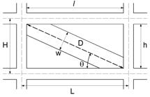
The best-known expression in the specialized literature for determining the width of the equivalent strut is that proposed by Mainstone (1974), given by Equation (1). It is used in the numerical simulations of this paper in the models with single concentric diagonal strut.
where
D is the length of the diagonal of the infill wall;
λH is calculated by
h is the masonry height;
Ew and tw are, respectively, the modulus of elasticity and the thickness of the infill masonry;
Ec and Ic are, respectively, the modulus of elasticity and the moment of inertia of the column;
θ is the angle of the diagonal strut measured from the horizontal;
H is the height between beam axes (floor-to-floor distance).
The expression proposed by Mainstone (1974) usually provides conservative values for the equivalent strut width. Other expressions, such as the one proposed by Durrani and Luo (1994), can also be used for the analyzes (Montandon, 2018; Galvão, 2022).
2.1.2 Adapted single diagonal strut models: frame-infill interaction
The main limitation of the model with a single concentric diagonal strut is that it is not able to capture the shear forces exerted by the diagonal strut on the frame members, especially on the columns, as shown in Figure 1. For this reason, corrections (adjustments) to the model of the single concentric diagonal strut are proposed in the literature and in codes.
The Brazilian code ABNT NBR 16868-1 (2020) recommends that the frame elements should be designed to resist the additional shear forces introduced by the diagonal strut. Therefore, the proprosed position of the resultant compressive forces for the design of the frame columns can be seen in Figure 3.

Position suggested by ABNT NBR 16868-1 (2020) for the resultant diagonal strut for the design of the columns.
In this paper, the models proposed by Basha and Kaushik (2019) and Trapani et al. (2023) were used to evaluate the effects of the infill wall-frame interaction by using adapted single-strut models.
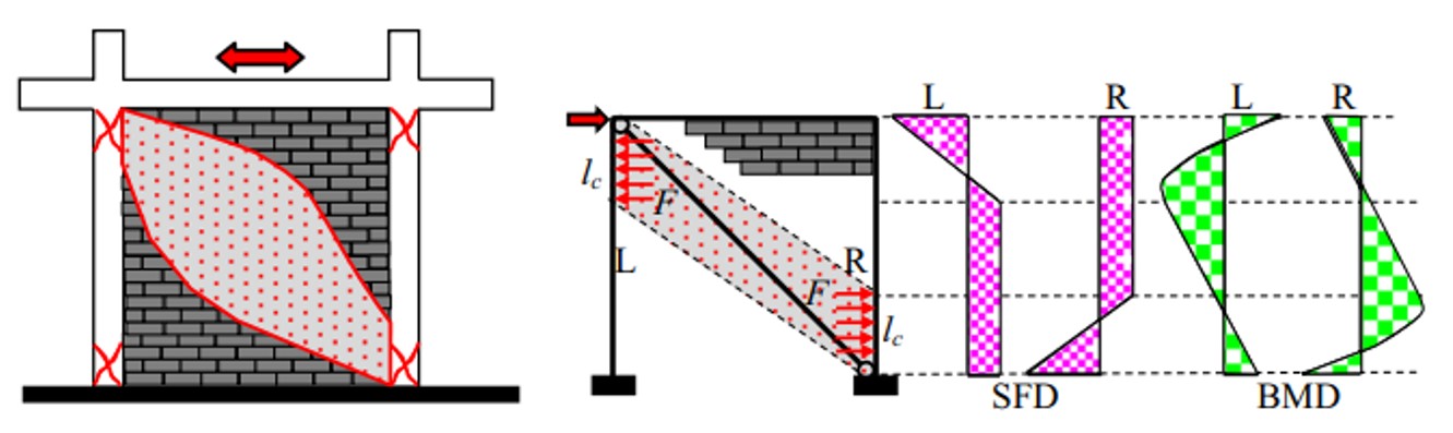
The model proposed by Basha and Kaushik (2019) improves the results of the model with a single concentric diagonal strut and uses the expression of Mainstone (1974). In this model, the axial force of the equivalent diagonal strut is transferred in the lateral direction, where it is uniformly distributed along the contact area between the column and the infill wall, as shown in Figure 4. This procedure aims to correct the main limitation of the model with a single concentric diagonal strut: the inability to capture the additional shear force in the columns in the contact area between the infill walls and the concrete frame.
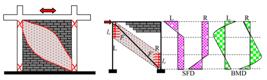
Experimental test results were used to validate the proposed model (Figure 4). Three frames were tested: one frame without infill walls (BF) and two frames with infill walls (IF-FB1 and IF-FB2). More details on these tests can be found in Basha and Kaushik (2019).
The expression used by Basha and Kaushik (2019) to determine the contact length lc (Figure 4) is as follows:
where w is the width of the diagonal equivalent strut, θc is the angle of the eccentric diagonal strut (Figure 4) in relation to the horizontal resulting from the solution of Equation 4:
where h and l are the height and the length the of the infill masonry wall, respectively.
The model proposed by Trapani et al. (2023) also mitigates the limitations of the single concentric diagonal strut model and has similarities with the model of Basha and Kaushik (2019). The main difference between the two models lies in how the axial force of the equivalent diagonal strut is transferred to the concrete frame. It is noted that the model of Basha and Kaushik (2019) restricts this transfer to the lateral direction, while the model proposed by Trapani et al. (2023) considers the contact area between the masonry and the frame in both the vertical and lateral directions (Figure 5). This model takes into account the presence of frictional forces between the masonry and the frame, an aspect that is not considered in the model of Basha and Kaushik (2019).

The model of Trapani et al. (2023) was validated by experimental tests by Mehrabi and Shing (1996) and Cavaleri and Trapani (2014) on six infilled reinforced concrete frames with different types of masonry.
Trapani et al. (2023) propose that the total shear force Vd,tot in the columns adjacent to the masonry infill is the sum of two components: the shear force of the column, determined from the frame model Vd,frame, and an additional force due to the interaction between the masonry infill and the structure Vd,inf:
The shear force Vd,inf results from the axial force along equivalent diagonal strut and the frictional force between the masonry and the structure:
where
(7)
(8)
(9)
μ is the friction coefficient, σv is the vertical compressive stress caused by the equivalent diagonal strut, t is the thickness of the infill wall and αl is the contact length.
The contact length considered in the model of Trapani et al. (2023) is assumed to be αl = 0.30l and 0.4l for l/h = 1; αl = 0.25l and 0.3l for l/h = 1.5; for windward and leeward columns, respectively. For the examples calculated in this paper, an interpolation was assumed for these values.
In the model by Trapani et al. (2023), the maximum shear force determined in the modeling is not adopted as an internal force in the column shear verifications. Consequently, the authors propose an average value for a contact area of the column with the masonry, which is defined as 1.5 times the height of the column cross-section (Figure 6). The shear force for the column verification is therefore composed of an average of 3 values from the range of 1.5hc, where hc is the height of the column cross-section (Figure 6).

Determination of the maximum shear force in the column for the design according to the model proposed by Trapani et al. (2023)
2.1.3 Multiple diagonal strut models
Another alternative for capturing additional shear forces exerted by the infill wall on the frame elements is to use models with multiple struts.
The studies conducted by Crisafulli and Carr (2007) show that the use of multiple diagonal struts (two or three struts) is an alternative to the single strut, as can be seen in Figure 7. In these models, the eccentricity of the diagonal struts in relation to the corners of the infill wall depends on the contact length z between the infill wall and the frame, which can be calculated using the analytical expression of Stafford-Smith (1967).
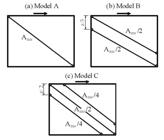
Models of a single strut (a), two struts (b), three struts (c): Crisafulli and Carr (2007).
Galvão (2022) proposes multiple strut models similar to those of Crisafulli and Carr (2007), as shown in Figures 8to 10. However, these have different eccentricities of the diagonal struts, as the contact lengths determined with the Stafford-Smith (1967) expression were significantly greater than those observed in the models simulated with FEM. In the proposal by Galvão (2022), the eccentricities of the struts are a function of the width of the equivalent diagonal strut (w), which in turn can be calculated using various expressions and methods available in the literature and in codes.
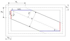
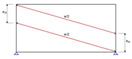
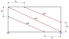
In the infilled frame shown in Figure 7, the effective contact lengths between column and infill wall (αefH) and between beam and infill wall (αefL) are determine by geometric calculations. These parameters result in the eccentricities eH and eL, which are also dependent on the cross-sectional heights of the column (hp) and the beam (hv).
In this paper, the two-strut model proposed by Galvão (2022) is used in the numerical simulations of Section 3 to evaluate the effects of the infill wall-frame interaction, calculating the width of the equivalent strut w using the expression of Mainstone (1974).
2.2 FEM models with the inclusion of the contact problem
Finite Element Method (FEM) modelling is widely used to evaluate the behavior of masonry infilled frames. However, the modeling of the elements can become complex if certain simplifications are not adopted. For notes on the refinement levels of FEM modeling for masonry, see Asteris et al. (2013).
In this paper, macro-modeling was employed to simulate the masonry infills (Figure 11), where the mortar, the unit and the mortar-unit interface are simulated as a continuum and homogeneous element.

The contact between the masonry infill and the concrete frame was simulated using the CONTACT 174 and TARGET 170 contact pair from the ANSYS program. The cohesion and friction between the surfaces were considered by the criteria of Coulomb’s law, as shown in Equation 14:
In Equation 14, τ is the mobilized shear strength, τ0 is the cohesion, μ is the friction coefficient between the surfaces, and σ is the contact pressure between the infill wall and the frame.
In this paper, the parameters of Equation 14 were estimated using the recommendations of ABNT NBR 16868-1 (2020) for the shear strength of the masonry.
3 NUMERICAL MODELING
3.1 Single-story frame
In order to compare the models with regard to the maximum shear force in the columns, infilled frames were selected, which were simulated using FEM (macro-modeling) by Galvão (2022). In this modeling, the frame elements and the masonry infills were simulated with the finite element PLANE182. The contact between the masonry infills and the concrete frame was simulated using the CONTACT172 and TARGET170 contact pair. The accuracy of the FEM modeling procedure was compared with experimental results from the literature, as shown in Galvão and Alva (2023).
The frames have the following geometric characteristics (Figure 12): a beam span of 6 meters, a storey height of 3 meters, a column cross-section of 19x40 (cm), a beam cross-section of 19x60 (cm) and a thickness of the infill masonry of 19 cm. The concrete has a characteristic compressive strength of 25 MPa, a longitudinal modulus of elasticity of 28 GPa and a Poisson’s ratio of 0.20. The lateral force applied was 300 kN.

In this example, the maximum shear force determined in the columns by the model with single concentric equivalent diagonal strut, by the model of Basha and Kaushik (2019), by the model of Trapani et al. (2023) and by the model with two struts was compared with the maximum shear force from the FEM analyzes of Galvão (2022). All the analyzes consider linear elastic materials.
Four infilled frames investigated by Galvão (2022) were selected and their mechanical properties can be found in Table 1. The abbreviations BVC and BCPV stand for concrete hollow blocks and clay bricks with hollow walls respectively.
In Table 1, Ey is the modulus of elasticity parallel to head joints, Ex is to the modulus of elasticity parallel to bed joints, ν is the Poisson´s ratio, μ is the friction coefficient between block and mortar, fbk is the characteristic compressive strength of the unit, and Ed is the modulus of elasticity along the diagonal strut direction.
3.2 Four-story frame
This example is a four-story frame designed to resist seismic loads in accordance with ABNT NBR 15421 (2023) and analyzed by Lemos (2025). This frame, identified as B (Figure 13), is part of a building with reinforced concrete structure and clay block masonry infills.

The distance between the floors is 3.0 m. In addiction to the dead weight of the structure (columns, beams and slabs), the additional dead weight is 1.0 kN/m2. There are masonry infills over all the beams on every floor, which has a weight of 6.50 kN/m. The live load on the slabs is 2.0 kN/m2. The masonry properties are the same of the infilled frame BCPV04P40V60 (see Table 1).
Three ultimate load combinations (including seismic loads) were performed to pre-dimension the cross-sections of the frame members without considering the contribution of the masonry infills.
Table 2 shows the seismic lateral loads of the building in the Y-direction, which were determined using the equivalent lateral load method. The following information was taken into account for the seismic load calculations: Building located in the city of Rio Branco-AC; category of importance II (factor I = 1.25); seismic zone 3; seismic category C; reinforced concrete frame with usual detailing for the seismic structural system (R = 3 and Cd = 2.5); and site class D.
The plane frame analysed is frame B, as shown in Figure 12. The distribution of seismic forces on the frames was based on their lateral stiffness. The seismic loads on frame B are given in Table 2.
The shear force in the columns was determined by the equivalent strut models and by FEM models using 3D finite elements and simulating the contact problem between masonry and frame. For all analyses, the materials were assumed to be linearly elastic. The equivalent strut models used were the single equivalent diagonal concentric strut, the model of Basha and Kaushik (2019), the model of Trapani et al. (2023) and the two-strut model proposed by Galvão (2022). ANSYS WORKBENCH 2019 R3 software was used for the FEM model (reference).
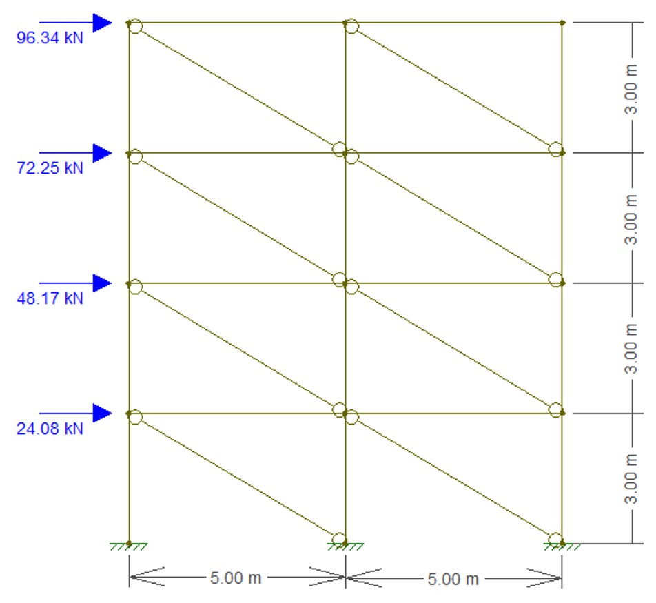
Figure 14 shows the seismic loads acting on the analysed frame with the single concentric diagonal struts to simulate masonry infills. Figure 15 shows the seismic loads applied to the FEM model simulated with the ANSYS software.
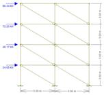

To simplify the modelling, the masonry was considered as a homogeneous and continuum element. The frame elements and the masonry infills were simulated using the finite element SOLID186. The contact between the masonry infills and the concrete frame was simulated with the CONTACT174 and TARGET170 contact pair. The cohesion and friction between the surfaces were considered using the Coulomb criterion according to Equation 10. The parameters were taken from the recommendations in ABNT NBR 16868-1 (2020), namely: COHE=0.15 MPa (cohesion); MU=0.5 (friction coefficient) and TAUMAX=1.40 MPa (maximum shear strength).
After a mesh refinement study, it was decided to use finite elements with a size of 0.075m for the exterior columns and 0.10m for the interior column and the infill walls.
4 RESULTS
4.1 Single-story frame
Figure 16 contains the values for the maximum shear force in the columns of the models analysed by Galvão (2022), including the values obtained by the aforementioned author using FEM, as well as the values of the the equivalent diagonal strut models discussed in this paper: SSM (single strut model), DSM (double strut model) by Galvão (2022), Basha and Kaushik (2019) and Trapani et al. (2023).
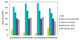
Figure 16 shows that the shear force determined by the single concentric diagonal strut leads to significantly lower values than those determined by the FEM. This confirms that this model is not able to adequately capture the maximum shear force in the column due to the interaction between the frame structure and the masonry infill. It is also noted that for the infilled frames with concrete blocks (BVC04P40V60, BVC14P40V60 and BCV24P40V60), the greater the stiffness, the greater the differences between the maximum shear force obtained with the single concentric diagonal strut model and the values obtained with the FEM.
The values of the model by Basha and Kaushik (2019) and the model by Trapani et al. (2019) were 82% and 40% higher, respectively, than the values determined using the FEM. Therefore, these models were conservative in estimating the maximum shear force in the column.
The two-strut model gives better results than the models with a single concentric diagonal strut and is closer to the FEM results, no less than 10% and on average about 3% higher than the FEM results.
Table 3 shows the ratio between the maximum shear force in the columns determined with the FEM and with the equivalent diagonal strut models in this paper.
4.2 Four-story frame
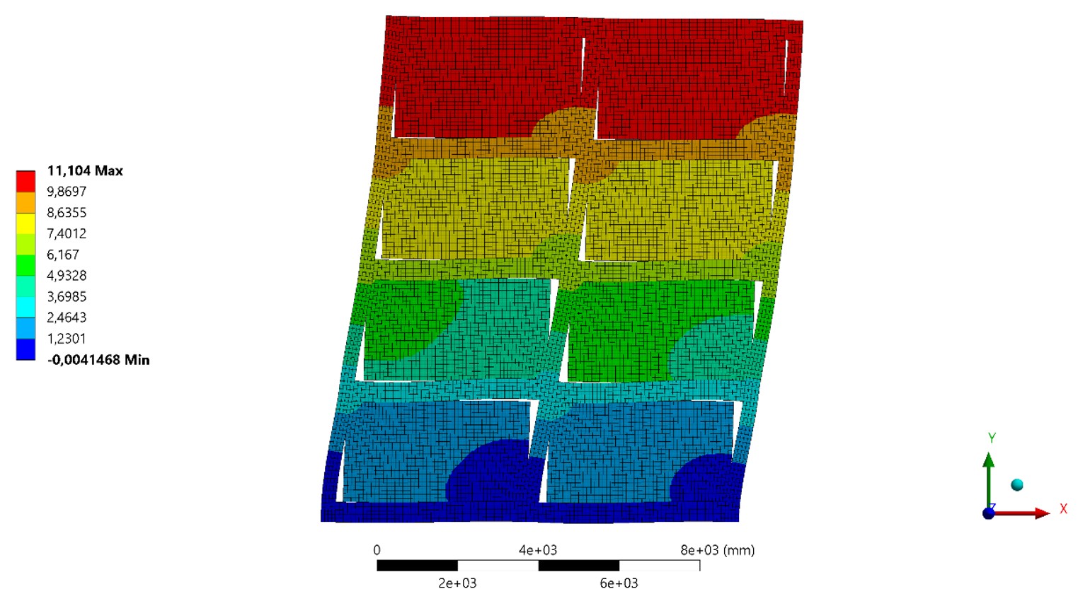
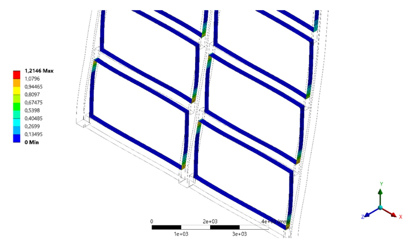
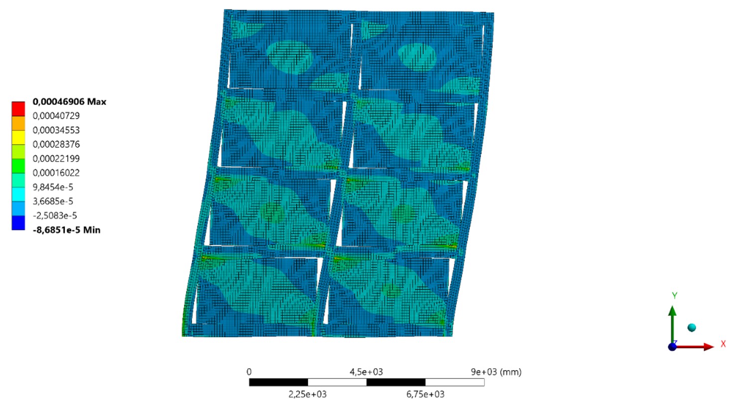
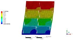
Figures 17 to 19 show the displacements and the main compressive strain of the infilled frames as well as the contact pressure points between the masonry infill and the concrete frame.


For the global analysis, Figure 20 shows the lateral displacements of the floors determined with the FEM model, the single strut model, the two-strut model and the bare frame model (without masonry infill).
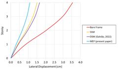
Figure 20 shows that the equivalent diagonal strut models using the Mainstone (1974) expression gave more conservative results compared to the FEM model. However, these were significantly better than the bare frame model (without masonry) for the assessing the lateral stiffness of the building.
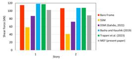
For the local analysis, Table 4 summarizes the maximum shear force in the interior column P5 and in the exterior column P6 for the different models used in this paper. Figures 21 and 22 show the maximum shear forces for these columns in the first two floors.

In the following comparisons, the results of FEM are used as the reference.
It should be noted at the outset that the single concentric diagonal strut model does not provide good results for determining the maximum shear force in the columns, so that the values are between 48% to 74% less than the FEM results.
On the other hand, the corrections proposed by Basha and Kaushik (2019) and Trapani et al. (2023) to the single concentric diagonal strut model are considered adequate to determine the maximum shear force in the columns for the purpose of design. The model by Basha and Kaushik (2019) provided 5% to 21% higher values compared to the FEM. The model by Trapani et al. (2023) in turn provided values between 5% lower and 21% higher compared to FEM.
Although the two-strut model proposed by Galvão (2022) was better than the single concentric diagonal strut model to determine the maximum shear force in the columns, the results were between 15% to 32% lower than those of the FEM.
Finally, it should be noted that simply neglecting the masonry infill walls in the structural model does not always lead to results that are favourable for safety. For the exterior column P6, the bare frame model underestimated the maximum shear force by 25% to 32% compared to the FEM model (Table 4 and Figure 21), which takes into account the contact between the masonry infill wall and the concrete frame.
5 CONCLUSIONS
This paper presented a comparative study was presented of different structural models to determine the shear force in concrete columns due to the interaction between masonry and structure under seismic loading for design purposes. Reference models based on FEM were used to consider the contact problem between masonry infill and concrete frame. All analyzes, FEM models and the equivalent diagonal struts models consider linear elastic materials. The equivalent diagonal models use the expression of Mainstone (1974).
Based on the numerical simulations performed in this study, the following conclusions are highlighted:
-
If the infill masonry in frames is overlooked, the maximum shear force occurring in the columns due to masonry infill-concrete frame interaction may be underestimated.
-
The classic single concentric diagonal strut can lead to relatively satisfactory results as far as the global displacements of the structure. However, this model is not suitable for the design of columns, as it leads to significantly lower results for the maximum shear force because it does not take into account the masonry-structure interaction.
-
Corrections to the single concentric diagonal strut model, aimed at structural design can lead to good estimates for the maximum shear force in columns, as proposed in the models by Basha and Kaushik (2019) and by Trapani et al. (2023). Between these two models, the model by Basha and Kaushik (2019) proved to be slightly more conservative.
-
The two-strut model proposed by Galvão (2022) gave significantly better results than the single concentric diagonal model for determining the maximum shear force in the columns, but these results were worse than those of the models of Basha and Kaushik (2019) and Trapani et al. (2023). Additional numerical simulations using other expressions for the width of the equivalent diagonal strut are necessary to better evaluate the efficiency of the two-strut model.
It is worth noting that the conclusions of this study are limited to linear elastic analyses. As suggestions for future research, it is recommended to consider the non-linear behavior of materials and to investigate alternative expressions for the equivalent diagonal strut width, in addition to the formulation of Mainstone (1974).
ACKNOWLEDGEMENTS
To National Council for Scientific and Technological Development – CNPq for the financial support (Process: 403378/2023-0).
-
Data availability:
Research data is only available upon request
References
-
Al-Chaar, G., Issa, M., Sweeney, S. (2002). Behavior of Masonry-Infilled Nonductile Reinforced Concrete Frames, Journal of Structural Engineering 128(8):1055-1063. https://doi.org/10.1061/(ASCE)0733-9445(2002)128:8(1055)
» https://doi.org/10.1061/(ASCE)0733-9445(2002)128:8(1055) -
Asteris, P. G., Cotsovos, D. M., Chrysostomou, C. Z., Mohebkhah, A., Al-Chaar, G. K. (2013). Mathematical micromodeling of infilled frames: State of the art, Engineering Structures 56:1905-1921. https://doi.org/10.1016/j.engstruct.2013.08.010
» https://doi.org/10.1016/j.engstruct.2013.08.010 -
Basha, S. H., Kaushik, H.B. (2019). A novel macromodel for prediction of shear failure in columns of masonry infilled RC frames under earthquake loading, Bulletin of Earthquake Engineering 17:2219-2244. https://doi.org/10.1007/s10518-018-00537-5
» https://doi.org/10.1007/s10518-018-00537-5 -
Basha, S.H., Kaushik, H.B. (2016). Behavior and failure mechanisms of masonry-infilled RC frames (in low-rise buildings) subject to lateral loading, Engineering Structures 111:233-245. https://doi.org/10.1016/j.engstruct.2015.12.034
» https://doi.org/10.1016/j.engstruct.2015.12.034 - Bertero, V., Brokken, S. (1983). Infills in Seismic Resistant Building, Journal of the Structural Engineering 109(6):1337-1361.
- Brazilian Association of Technical Standards (2020). NBR 16868-1: Structural masonry - Part 1: Design (In Portuguese), ABNT (Rio de Janeiro).
- Brazilian Association of Technical Standards (2023). NBR 15421: Design of seismic resistant structures (in Portuguese), ABNT (Rio de Janeiro).
-
Cavaleri, L., Trapani, F.D. (2014). Cyclic response of masonry infilled RC frames: experimental results and simplified modeling, Soil Dynamics and Earthquake Engineering 65:224–242. https://doi.org/10.1016/j.soildyn.2014.06.016
» https://doi.org/10.1016/j.soildyn.2014.06.016 -
Chrysostomou, C.Z., Asteris, P.G. (2012). On the in-plane properties and capacities of infilled frames, Engineering Structures 41:385-402. https://doi.org/10.1016/j.engstruct.2012.03.057
» https://doi.org/10.1016/j.engstruct.2012.03.057 -
Crisafulli, F.J., Carr, A.J. (2007). Proposed Macro-Model for the Analysis of Infilled Frame Structures, Bulletin of the New Zealand Society for Earthquake Engineering 40(2):69-77. https://doi.org/10.5459/bnzsee.40.2.69-77
» https://doi.org/10.5459/bnzsee.40.2.69-77 - Decanini, L.D., Fantin, G.E. (1987). Modelos simplificados de la mampostería incluida en pórticos - Caracteristicas de rigidez y resistencia lateral en estado limite, Jornadas Argentinas de Ingeniería Estructural, v.2, Buenos Aires, Argentina, p.817-836, 1987.
- Durrani, A.J., Luo, Y.H. (1994). Seismic retrofit of flat-slab buildings with masonry infills. Proceedings from the NCEER Workshop on Seismic Response of Masonry Infills, National Center for Engineering Earthquake, Buffalo, New York.
-
El-Dakhakhni, W.W., Elgaaly, M., Hamid, A.A. (2003). Three-Strut Model for Concrete Mansory-Infilled Steel Frames, Journal of the Structural Engineering 129(2):177-185. https://doi.org/10.1061/(ASCE)0733-9445(2003)129:2(177)
» https://doi.org/10.1061/(ASCE)0733-9445(2003)129:2(177) -
Fiore, A., Netti, A., Monaco, P. (2012). The influence of masonry infill on the seismic behaviour of RC frame buildings, Engineering Structures 44:133-145. https://doi.org/10.1016/j.engstruct.2012.05.023
» https://doi.org/10.1016/j.engstruct.2012.05.023 -
Galvão, L. F. (2022). Contributions to numerical analysis of buildings with participating masonry walls, Master Thesis (in Portuguese), Federal University of Uberlândia, Brazil. http://doi.org/10.14393/ufu.di.2022.150
» http://doi.org/10.14393/ufu.di.2022.150 -
Galvão, L. F., Alva, G.M.S. (2023). Structural analysis of RC infilled frames with participating masonry: a proposal procedure for multi-strut models, IBRACON Structures and Material Journal 16(4): e16409. https://doi.org/10.1590/S1983-41952023000400009
» https://doi.org/10.1590/S1983-41952023000400009 -
Kim, J.Y., Yu, E., Kim, D.Y., Kim, S.D. (2009). Calibration of analytical models to assess wind-induced acceleration responses of tall buildings in serviceability level, Engineering Structures 31:2086-2096. https://doi.org/10.1016/j.engstruct.2009.03.010
» https://doi.org/10.1016/j.engstruct.2009.03.010 -
Lemos, M. F. O. (2025). Additional shear on columns of concrete buildings subjected to seismic loads due masonry infills, Master Thesis (in Portuguese), Federal University of Uberlândia, Brazil. https://doi.org/10.14393/ufu.di.2025.175
» https://doi.org/10.14393/ufu.di.2025.175 -
Liauw, T.C., Kwan, K.H. (1984). Nonlinear behavior of non-integral infilled frames, Computers and Structures 18(3):551-560. https://doi.org/10.1016/0045-7949(84)90070-1
» https://doi.org/10.1016/0045-7949(84)90070-1 - Mainstone, R.J. (1974). Supplementary note on the stiffness and strengths of infilled frames, Building Research Station, Garston, United Kingdom.
-
Mehrabi, A.B., Shing, P.B., Schuller, M.P., Noland, J.L. (1996). Experimental Evaluation of Masonry-Infilled RC Frames, Journal of the Structural Engineering 122(3):228-237. https://doi.org/10.1061/(ASCE)0733-9445(1996)122:3(228)
» https://doi.org/10.1061/(ASCE)0733-9445(1996)122:3(228) -
Milanesi, R. R., Morandi, P., Magenes, G. (2018). Local effects on RC frames induced by AAC masonry infills through FEM simulation of in-plane tests, Bulletin of Earthquake Engineering 16:4053-4080. https://doi.org/10.1007/s10518-018-0353-5
» https://doi.org/10.1007/s10518-018-0353-5 -
Montandon, G. A. (2018). Structural models for analysis of infilled frames with masonry in reinforced concrete buildings, Master Thesis (in Portuguese), Federal University of Uberlândia, Brazil. https://doi.org/10.1590/S1983-41952019000500006
» https://doi.org/10.1590/S1983-41952019000500006 -
Papia, M., Cavaleri, L., Fossetti, M. (2003). Infilled frames: developments in the evaluation of the stiffening effect of infills, Structural Engineering and Mechanics 16(6):675-693. https://doi.org/10.12989/sem.2003.16.6.675
» https://doi.org/10.12989/sem.2003.16.6.675 - Paulay, T., Priestley, M.J.N. (1992). Seismic design of reinforced concrete and masonry buildings, Wiley (New York).
- Silva, L. R. (2014). Contribution of masonry panels on analysis of reinforced concrete frames, Master Thesis (in Portuguese), Federal University of Santa Maria, Brazil.
- Stafford-Smith, B. (1967). The composite behaviour of infilled frames, Tall Buildings: 481-493. Proc. of a Symposium on Tall Buildings, 1966, Southampton.
-
Su, R.K.L., Chandler, A.M., Sheikh, M.N., Lam, N.T.K. (2005). Influence of non-structural components on lateral stiffness of tall buildings, The Structural Design of Tall and Special Buildings 14:143-164. https://doi.org/10.1002/tal.266
» https://doi.org/10.1002/tal.266 -
Trapani, F. D., Bogatkina, V., Petracca, M., Camata, G. (2023). Evaluation of the additional shear demand due to frame-infill interaction, Procedia Structural Integrity 44:496-503. https://doi.org/10.1016/j.prostr.2023.01.065
» https://doi.org/10.1016/j.prostr.2023.01.065 -
Uva, G., Raffaele, D., Porco, F., Fiore, A. (2012). On the role of equivalent strut models in the seismic assessment of infilled RC buildings, Engineering Structures 42:83-94. https://doi.org/10.1016/j.engstruct.2012.04.005
» https://doi.org/10.1016/j.engstruct.2012.04.005 -
Wararuksajja, W., Srechai, J., Leelataviwat, S., Sungkamongkol, T., Limkatanyu, S. (2021). Seismic design method for preventing column shear failure in reinforced concrete frames with infill walls, Journal of Building Engineering 44: e102963. https://doi.org/10.1016/j.jobe.2021.102963
» https://doi.org/10.1016/j.jobe.2021.102963 -
Yekrangnia, M., Mohammadi, M. (2017). A new strut model for solid masonry infills in steel frames, Engineering Structures 135: 222-235. https://doi.org/10.1016/j.engstruct.2016.10.048
» https://doi.org/10.1016/j.engstruct.2016.10.048
Edited by
-
Editor:
Marco L. Bittencourt
Research data is only available upon request