Optical Fiber Head Sensors with Controlled Polarization for Flow Measurement in Pipelines
Abstract
This experimental study discusses developing methodologies linked to optical fiber sensing (OFS), focused on structural health monitoring with sensors based on multimodal interference and the core diameter mismatch approach to monitor the flow of single and two-phase pipeline systems. Singlemode-multimode-singlemode (SMS), singlemode-nocore-singlemode (SNCS), singlemode-multimode-singlemode-multimode-singlemode (SMSMS), singlemode-multimode-erbium doped-multimode-singlemode (SMErDMS), and singlemode-multimode-dispersion compensation-multimode-singlemode (SMDCMS) were the five different heads sensors used in the sensor structure. Results showed that the polarization effect causes a spike in the sensitivity levels and alters the sensor's behavior with a polarizer among the optical source path. Sensitivity values of SMS sensor changed from 0.027 dBm/(h/m³) to 0.041 dBm/(h/m³) for the single-phase flow measurement tests; the SNCS structure's sensitivity changed from 0.093 dBm/(h/m³) to 0.221 dBm/(h/m³); and the SMSMS sensor's sensitivity changed from 0.862 dBm/(h/m³) to 1.122 dBm/(h/m³). The sensitivity values for the two-phase flow increased for the SMS from -0.126 dBm/(h/m³) to -0.288 dBm/(h/m³) and for the SMErDFMS from -0.028 dBm/(h/m³) to -0.929 dBm/(h/m³), respectively. All structures had a good acceptable coefficient of determination and the polarization mode maintained by a polarizer also to prevent random power coupling between the polarization modes and assisted in controlling the optical power.
Index Terms
Core Diameter Mismatch; Multimode Interference; Optical Fiber Sensors; Flow Measurement
I. INTRODUCTION
Recent technological advancements have commended study findings and their practicality, emphasizing optical fiber sensors for their benefits, which include their small size, low complexity, immune response to electromagnetic interference, and lack of an electrical signal. Because of these benefits, the sensors are appealing for civil structure monitoring solutions, like multi-parameter measurement in the oil and gas exploration sector. When compared to traditional electronic sensors, their detection techniques, and the cost-benefit ratio as a deciding factor, and these sensors' other features demonstrate that they are a very excellent choice for simple measurement [1].
Considering the evolutionary history, oil and gas pipeline parameters have been measured in real time applying other optical fiber sensing technologies, so a number of research studies have examined singlemode-multimode-singlemode (SMS) fiber sensing structures to filter and quantify different properties. Among these sensors, the option of singlemode-multimode-singlemode sensors provides several benefits, including ease of fabrication and operation and the capacity to measure variables including temperature, vibration [2], displacement, and deformation [3]; they have become more and more common. Based on multimodal interference phenomena, which occurs when light propagates through a multimode fiber and finds a core diameter mismatch, such SMS structures allow high-sensitivity and resolution measurements. This phenomenon makes it possible to identify even the smallest alterations in the immediate surroundings.
For a variety of detecting applications in optical fiber-based systems, fusion sensor structures in optical fibers provide reliable signal transmission and reduced insertion loss [4]. By detecting physical characteristics for both simple and complex jobs, sensors based on multimodal interference can solve problems in civilian structures without causing any damage to the structures themselves [5]. Such as interferometry with and without core diameter mismatch [6,7]. In this technological niche, such research results showed a variety of output options that are linked to devices like Mach-Zehnder interferometers, Sagnac interferometers, and Fabry-Perot interferometers, which operate on singlemode-multimode-singlemode structures [8,9].
The power of the optical signal is affected by mode coupling and interference effects carried on by the varying core sizes in SMS architectures [9]. The application of the sensing region in optical sensing is made possible by its great sensitivity to external influences. This allows for more accurate measurements and qualitative assessments of the parameter being studied, with an emphasis on changes in the interference pattern in these sensors. Due to their practicality and simplicity through the use of multimodal interference, these fiber structures—which are created by fusion splicing singlemode and multimode fiber sections—have garnered a lot of attention as technology in this field has advanced to the present day. This has resulted in unique optical properties that are appropriate for sensing [10,11].
The application of the core diameter mismatch technique to the SMS structures has demonstrated its real employability in various industrial fields, such as temperature measurement, deformation monitoring or curvature, measurement of the refractive index of fluids, and even in medical applications. Their versatility makes them a highly promising technology for use in a wide range of scientific and industrial research fields [12,13,14,15]. It is reliable to make accurate measurements when you use the resources that come with multimodal interference, and this also opens up a lot of new possibilities and technological advances in the optical detection processes [16,17].
Traditional SMS (Singlemode-Multimode-Singlemode) sensors rely on modal interference within a uniform multimode fiber (MMF) core, and this work innovates by introducing controlled core diameter variations along the MMF section. So this core mismatch creates deliberate perturbations in the optical path, enhancing sensitivity to micro-scale strain and thermal changes induced by fluid flow. Unlike conventional SMS designs, this approach exploits geometric asymmetry to increase spectral shifts (wavelength/intensity) under flow-induced perturbations. The diameter mismatch acts as a built-in transducer, converting mechanical stress from fluid turbulence into measurable optical signals.
This work presents a significant theoretical advancement in optical fiber sensing (OFS) by integrating multimodal interference principles with core diameter mismatch techniques to monitor flow dynamics in single and two-phase pipeline systems. Furthermore, the formal academic explanation of its theoretical novelty is supported by experimental validation. This work establishes three pillars of novelty known as structural hierarchy, where cascaded/heterogeneous fiber heads like SMSMS, SMErDMS, and SMDCFMS create engineered interference landscapes for multi-parameter flow extraction; second is the polarization-through-design, where the sensor geometry intrinsically suppresses polarization noise, enabling ultra-stable operation in dynamic pipeline environments. And third, the material-function integration where strategic material choices like NCF, EDF, and DCF introduce active sensing capabilities as gain, dispersion control absent in conventional SMS/SNCS sensors.
A flexible approach was employed in this study to fabricate optical head sensors as an active sensing element that interacts with the environment (e.g., flow, pressure, temperature) and transduces these physical changes into measurable optical signals (such as intensity, wavelength shift, or phase change by integrating various optical fiber architectures, which were employed in a pipeline monitoring system to observe the characteristics of single-phase and two-phase fluids. The initial structure employed was the singlemode-multimode-singlemode configuration, followed by the utilization of the Singlemode-Nocore-Singlemode (SNCS) structure. The main head sensing area in the middle was modified to create more intricate structures.
Specifically, different fiber, types such as Singlemode-Multimode-Singlemode-Multimode-Singlemode (SMSMS), sequential Singlemode-Multimode-Erbiumdoped-Multimode-singlemode (SMErDMS), and Singlemode-Multimode-Dispersioncompensation-Multimode-Singlemode (SMDCFMS) were used in a sequential manner. Some of these sensors were utilized to quantify single-phase flow, and others to measure two-phase flow [18,19]. In this particular situation, these sensing devices were employed to assess the flow parameter related to the curvature of the fiber, and this choice was made due to the remarkable sensitivity of this structure, as well as its simple production method, possible affordability, and convenience of handling [20,21].
II. GENERAL THEORETICAL PRINCIPLES
A. Concepts of Multimodal Optical Interference Sensors
According to their intrinsic benefits, such as being tolerant to electromagnetic interference, multimodal interference (MMI) structures are ideal for deployment in difficult situations [22,23]. The biocompatibility of optical fibers, which makes these sensors appropriate for biomedical applications, is combined with their simple integration into organisms or systems. Optical fibers are used for detection and remote monitoring, which makes them advantageous in applications where access is challenging and there are hazards [24]. In this context, the benefits discussed above, particularly for MMI-based sensors, also have some unique features, like low manufacturing costs, easy operationalization and implementation, high sensitivity to different physical parameters, accurate measurement, low noise, and increased flexibility [25].
Fiber-optic interferometry sensors use multiple beams that propagate along the fiber, where the interference can be constructive as well as destructive; leading to transmission peaks or dips that cover a large wavelength range. So, the changes in the effective path and the places of the spectral peaks and dips, modal interference sensors can pick up on changes in the environment, like when the temperature or tension changes, and the factors help in determining the variation of a quantity by measuring the variations in the intensity, wavelength, phase, or bandwidth [26,27].
The Fabry-Perot interferometer (FPI), Sagnac Loop interferometer, and Mach-Zehnder interferometer (MZI) are the three primary forms of MMI, based on their operation principle, and they form the foundation of SMS fiber constructions [28,29]. With its uncoated multimode fiber (MMF) section between two pieces of singlemode fiber (SMF) that are used as mode couplers because of the core diameter mismatch (CDM) technique to split and recombine light to form an in-line MZI structure, the SMS sensor functions as a Mach-Zehnder interferometer. The SMS sensor functions on the following principle: Higher order modes are excited when light is transmitted into a multimode fiber from a singlemode fiber. As they spread over the MMF, an interference pattern is produced [30].
Changes in the refractive index of the fiber can be measured using the interference pattern variation, allowing for the measurement of various physical parameters such as temperature, strain, and displacement [31,32,33]. The MMF section is capable of carrying many guided modes, where the difference in phase between them has to be a multiple of 2π; hence, all the modes can interfere in phase, and in that way, the input can be reproduced and the effect is considerably influenced by the distance L of the sensing element in the structure [34,35,36].
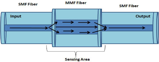
In the initial SMF segment (SMF input), as illustrated in Fig. 1, the input light propagates. Once it reaches the MMF, a number of modes are sequentially excited and propagate along the MMF fiber over the core and cladding. As the various modes move through the MMF, interference is produced. At last, light recouples at the final SMF output [37].
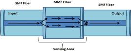
Multimodal interference phenomenon schematic based on the core diameter mismatch technique in the SMS structure in optical fiber
Due to the elastic deformation and the photo-elastic effect of the optical fiber, curvature may be associated with the difference between the modes that vary relatively to the flow that passes the sensor head. When the curvature deforms the fiber, it causes the asymmetric stress distribution, which can affect the refractive index via the photo-elastic effect and either the mode coupling, where the energy is transferred between the core and cladding modes reflected in the intensity attenuation and wavelength shifts. So, the generated optical spectrum will change induced by a curvature where the mechanical stress from fluid flow alters the optical spectrum through mode coupling and photo-elastic effects. As a result, the difference related to the variation of the fluid in single-phase or two-phase flow presents a direct relationship to the curvature that the fiber suffers from the water flow pressure, so that the curvature can be obtained according to the analysis of changes in the transmission spectrum where the spectral analyses of sensors leverage complementary can be analyzed in the frequency domain [38].
According to the theory underlying SMS and SMSMS fiber structures, the fundamental mode propagating in the single-mode fiber (SMF) possesses circular symmetry, characterized by a field distribution E(r,0). When this light mode is launched into the multimode fiber (MMF) section, it excites a superposition of the MMF’s eigenmodes, denoted as {LPnm}. The number of supported LP0m modes that can propagate within the MMF is determined by the fiber’s core diameter, numerical aperture, and the operating wavelength, as described by the modal analysis of the multimode waveguide. The calculation in [38,39] which dictates how many radially symmetric (LP₀ₘ) modes are supported can determine the number of LP0m modes that can propagate in the multimode fiber:
Where r is the core radius of the multimode fiber, nco and ncl are the refractive indices of the core and cladding of the multimode fiber, respectively and λ is the operating wavelength in free space. While light propagates along the MMF, it interferes with itself in a number of excited modes of LP0v, where ν is the mode number. Following a predetermined distance of propagation, the phase difference ϕmn between two modes, LP0m and LP0n, can be represented as [40,41]:
Where Lp is the propagation distance, um = π (m − 1/4) and un = π (n − 1/4) are the normalized propagation constants and correspondent roots of the Bessel function of zero order, and r, nco and N are the radius of the MMF core, the refractive index of the MMF core, and the natural integer number, respectively. γ is the light wavelength in the free-space and βm and βn are the longitudinal propagation constants for the modes m and n. [41].
With the use of the orthogonality properties between the eigenvectors of the modes of light in the multimode fiber and the input Er,z field and its output value in the case of singlemode fiber, we can compute the impairment loss by applying the following formula [20,40]:
Where cm e βm are the correspondent excitation coefficients for each of the modes and the propagation constants, respectively; z is the length of the MMF fiber, and M is the total amount number of guided modes [10].
B. Sensors Based on Core Diameter Mismatch
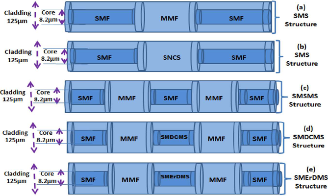
Fig. 2 (a) illustrates the optical fiber configuration of the SMS (singlemode-multimode-singlemode) sensor, which is created by joining a multimode fiber (MMF) with two singlemode fibers at its extremities. The sensor region, measuring 5 mm, is positioned in the core of the structure and is flanked by two singlemode fibers [41]. This architecture allows for the development of optical sensors using optical fiber, which can detect changes in the environment by analyzing multimodal interference. This particular SMS fiber sensor has the capability to function as a fluid flow meter, and may also be utilized as a hot wire. In this situation, the presence of a gas flow causes the dissipation of heat that is generated by light, resulting in a change in the transmission spectrum towards the blue end of the spectrum. These SMS fiber sensors are utilized in applications for fluid flow measurement, specifically for monitoring airflow [42].

The sensor structure generated by splicing is depicted in the schematic diagram. (a) Sensor for fiber structure utilizing spliced singlemode-multimode-singlemode fibers (b) The core fiber structure is made up of spliced singlemode-nocore-singlemode fibers. (c) The SMSMS structure consists of spliced singlemode-multimode-singlemode-multimode-singlemode fibers.d) SMDCMS structure consists of spliced singlemode-multimode-dispersion compensation-multimode-singlemode e) SMErDCMS structure consists of singlemode-multimode-erbium doped-multimode-singlemode
The configuration seen in Fig. 2 (b) is referred to as singlemode-nocore-singlemode (SNCS). It involves the placement of a nocore multimode optical fiber between two singlemode sections, with the splicing occurring at the ends. The NCF allows for the propagation of light through the fiber in many modes [43].
The sensor operates on a similar basis as the SMS, utilizing its great sensitivity to multimodal interference effects in measurements like refractive index and temperature [44]. The primary distinction lies in the structure of the SNCS, which operates as a multimode fiber lacking cladding around its core. It assumes that the surrounding material serves as a no-core fiber coating and eliminates the necessity to remove or damage the fiber cladding. As a result, the SNCS can directly detect changes in the refractive index (RI) around it, and this change in the surrounding material influences how light travels through the no-core fiber, causing variations in the light spectrum that comes out of the SNCS fiber [45,46,47]. This change affects the interference conditions between the modes, resulting in shifts in the positions of transmission peaks or dips in the output spectrum, as well as possible changes in their intensity. These spectral changes can be measured and analyzed by an Optical Spectrum Analyzer (OSA), which records the transmission or reflection spectrum as a function of wavelength or frequency, and especially this paper presents a classic frequency domain analysis.
Wang et al. were the first to suggest an SNCS fiber that used an NCF instead of an MMF in an SMS fiber structure for RI detection. The NCF was made by using hydro-fluoric acid (HF) to wet-corrode the coating of a regular MMF. The result of the RI sensor showed high sensitivity and this factor relative to the RI increases as the diameter of the NCF decreases but is independent of the length of the NCF. It makes possible to improve the sensitivity of RI sensors with an SNCS fiber structure, but the disadvantage arises from the fiber etching process, which is dangerous due to the use of HF acid, and the precise control of the diameter and surface roughness is very difficult [30,45,48].
The SMSMS fiber sensor consists of a singlemode fiber connected to a multimode fiber, followed by another singlemode fiber, and then another multimode fiber, and finally ends with a singlemode fiber. The SMSMS fiber sensor consists of a singlemode fiber connected to a multimode fiber, followed by another singlemode fiber, and then another multimode fiber, and finally ends with a singlemode fiber. Regarding its advantages, as shown in Fig. 2 (c) the SMSMS fiber sensor has a more complex structure than the SMS sensor, but offers higher sensitivity and wider dynamic range in order of its cascaded multimode interference regions enhances the sensor’s ability to respond to a broader range of flow-induced perturbations, driven to higher sensitivity to small flow changes and sustained linear response at higher flow rates. On the other hand, it is also resistant to electromagnetic interference and corrosion; therefore, it can be used for non-intrusive measurement of flow rates [49].
Knowing that dynamic range is the span between the smallest and largest measurable values of a physical quantity in our paper case, the flow rate that the sensor can detect with acceptable accuracy and resolution. In our fiber optic flow sensors, the lower limit corresponds to the minimum flow rate that produces a measurable and distinguishable optical signal change above the noise floor and the upper limit is the maximum flow rate at which the sensor’s response remains linear or predictable before nonlinear effects.
The SMSMS structure, by virtue of its cascaded multimode interference regions, enhances the sensor’s ability to respond to a broader range of flow-induced perturbations. This structural complexity translates into two considerable details like: Higher sensitivity to small flow changes (improving the lower detection limit) and sustained linear response at higher flow rates (extending the upper detection limit).
The working principle of the SMSMS structure is also based on multimodal interference generated between the modal sections of the fiber, and when light is injected from the first singlemode section to the first MMF section, it then excites various modes in the first multimode fiber section that interfere with each other to produce a unique output signal. The signal then propagates through the second singlemode section and excites several modes in the second multimode section, which again interfere with each other to produce a different output signal. Finally, the signal propagates through the third singlemode fiber section and produces a final output signal [50].
SMSMS fiber sensors can be used to measure various physical and chemical properties, including temperature, voltage, and refractive index. The design of SMSMS fiber sensors involves optimizing the length and diameter of the singlemode and multimode fiber sections to achieve the desired sensitivity and resolution. The SMSMS fiber structure has the advantage of being compact, low-cost, and easy to manufacture [51,52].
From an analysis of the structures of different sensor heads used in this work, it can be seen that SMS, SMSMS, SMErDFMS, and SMDCFMS fiber sensors are all optical fiber sensors that can be used for single-phase and two-phase flow measurements. The SMSMS sensor has a more complex structure than the SMS fiber sensor and offers greater sensitivity as well as a wider dynamic range. The SMErDFMS fiber sensor based on Erbium doped fiber as shown in Fig. 2 (e) has a high sensitivity and a very fast time response, and the Erbium doped fiber can increase the sensitivity of the sensor. While erbium-doped fibers are widely known for their use in optical amplifiers (EDFAs) in telecommunications, where they amplify optical signals by stimulated emission when pumped at specific wavelengths. In this flow sensor application, the erbium doping mainly influences the sensor's optical response characteristics. It typically affects: The sensitivity to strain, bending, and micro-curvature induced by fluid flow pressure.
Finally, in the case of Fig. 2 (d) the dispersion-compensating fiber-based SMDCFMS sensor has the advantage of a low-temperature cross-sensitivity. In summary, choosing a dispersion-compensating fiber-based SMDCFMS head sensor allows leveraging negative dispersion to counteract signal degradation, thereby improving optical signal integrity, sensor sensitivity, linearity, and reliability in dynamic flow measurement environments, especially when combined with polarization control and multimodal interference effects. [53,54].
C. Direct Action and Control of Polarization Effects
The phenomena of polarization control in optical fiber sensors is a well-established approach used to change parameters in various detecting applications. It has been extensively researched and utilized. The utilization of a fiber polarization controller to alter and stabilize the polarization state of light can exert a substantial influence on the performance of the detection system. To enhance the performance of the sensing process and achieve higher sensitivity and precision, it is possible to adjust the sequential interference patterns and signal characteristics by implementing mechanisms that govern the effects of polarization and this may be done for various parameters [55,56].
Polarization control devices in optical fiber sensors are a widely accepted approach that enables the adjustment and stabilization of the light's state. These effects are advantageous for reducing polarization-related noise and maximizing the signal-to-noise ratio in optical fiber sensors, and it enables the modification and stabilization of the light's state [57]. When the polarization modes travel through the fiber with a high level of birefringence, they propagate at different speeds, causing a phase shift that is sensitive to external influences. Therefore, it is crucial to take these factors into account when introducing light with a specific polarization into the sensor. This technique has a substantial effect on the performance of sensors, as it allows for the optimization of interference patterns and signal properties. This optimization leads to improved sensitivity and accuracy in sensor performance [58,59].
Controlling polarization is generally regarded as advantageous, primarily for reducing polarization-related noise and enhancing the signal-to-noise ratio in optical fiber sensors. Nevertheless, the impact on sensitivity can vary depending on the configuration of the sensor. Considering the impact of polarization control on the detection process using optical sensors and the decision of whether to utilize a fiber polarization controller are both crucial. This is particularly accurate when comparing the sensitivity of various structures, such as SMS and SNCS sensors, for the purpose of detecting flow in pipelines. Polarization control is essential for ensuring the accuracy and dependability of the detection system in this scenario. The fiber polarization controller is used to change the polarization state of light, enabling precise control over its orientation [60,61].
This polarization control is particularly important in the real application of optical fiber sensors since it can affect the interference patterns and characteristics of the obtained signal associated with the parameters of the sensing elements. The presence of multiple modes in MMI sensors can result in polarization-dependent effects; the polarization state of light affects the interference patterns generated in the multimode region of the sensor. This fact raises the need for the implementation of mechanisms for the control and stabilization of the polarization, thus contributing to ensuring a consistent and accurate parametric measurement process. For this, a very practical structure is the use of a fiber polarization controller that allows fine adjustment and optimization of the polarization state, thus increasing the sensitivity and reliability of the SMS sensor for flow measurement [61,62].
The circularly symmetry of optical fibers are not perfect because of unwanted residual birefringence that is added during the manufacturing process and therefore they don't keep the state of polarization. In this case, to reduce the deleterious contributions of light polarization in interferometric fiber sensors [63], polarization maintaining (PM) fibers or high birefringence fibers is used. In many of applications, the state of polarization must remain stable, but the PM fibers maintain polarization only when the input polarization is horizontal or vertical.
Otherwise, the relative phases of the horizontal and vertical components vary unpredictably.
And in high birefringence fibers, the coupling between the two modes is much smaller, and the same limitation is observed [64].
In this work, sensitivity is defined as amplitude sensitivity, representing the change in optical power loss (in decibels) per unit of volumetric flow measured (cubic meters per hour). Sensitivity corresponds to the slope of the sensor response curve, which relates the output signal, as in this case of optical power in dBm, to the input parameter, which here was the flow rate in m³/h. This metric quantifies the sensor’s ability to detect flow variations by converting mechanical effects on the optical fiber (such as micro-curvature induced by fluid pressure) into measurable changes in transmitted optical power. Mathematically, if the sensor response is represented by the function P=f(Q), where P denotes the sensor output and Q represents the flow rate, then the amplitude sensitivity S can be expressed as:
Where ΔP is the change in optical power (dB), and ΔQ represents the variation in volumetric flow (m³/h). The values reported in this study are derived from the slope of optical power response curves fitting measured data under different flow conditions. Controlling polarization states is critical to stabilize these measurements and reduce noise caused by modal coupling and birefringence effects. For a linear response, this is a constant slope, and for nonlinear responses, like in the case of our tests of polynomial curves, the sensitivity varies with Q and can be evaluated locally as the slope of the tangent line at a given point. When the sensor response is fitted to a polynomial curve (e.g., a second-order polynomial), the sensitivity at any flow rate Q is given by the first derivative of that polynomial at Q.
To verify the effect of flow measurement based on the curvature effect causing optical power losses, the amplitude sensitivity was calculated based on polynomial regression fitting. Based on the data, it was possible to plot according to the correlation of the values presented in the graphs, and it was deduced that the smallest power loss based on the curvature diameter demonstrated high sensitivity. So, when the fiber is bent from a higher flow rate, it results in more power loss in the fiber, where more light interacts with the surrounding effects, and consequently, this action results in an improvement in the sensitivity value.
III. EXPERIMENTAL SETUP APPROACH
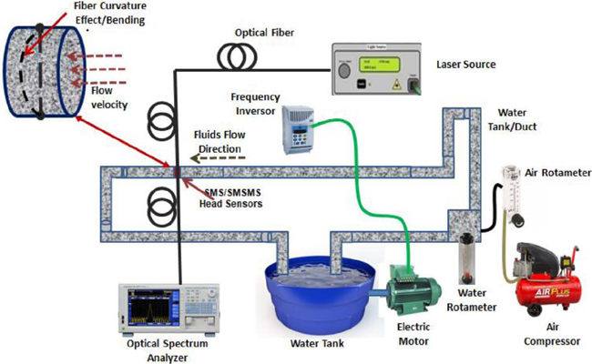
The schematic diagram in Fig. 3 illustrates the experimental mechanism. It includes a light source emitting a broad spectrum of light at a wavelength of 1550 nm. The light is guided through a fiber to the sensor structure. The transferred power spectrum is then analyzed using an OSA spectrum analyzer. The sensors function as a Mach-Zehnder interferometer. The fibers utilized have core/cladding diameters of roughly 8.2/125 μm and 105/125 μm for single-mode fiber (SMF-28 from Corning, Inc.) and multi-mode fiber (FG105-LCA from Thorlabs, Inc.), respectively. The length of the step-index multimode fiber (MMF) is roughly 5 mm, while the length of the conventional single-mode fiber (SMF) is around 20 mm. The sensors experience a curvature effect due to the pressure exerted by water, resulting in a power loss along the fiber inside the pipe. The system is employed for the purpose of monitoring and quantifying the rate of water flow. The methods involved adjusting the water flow in increments of 5 liters per minute, which is equivalent to steps of 0.3 m³/h. To analyze and regulate the polarization level, a fiber polarization controller operating at a wavelength of 1550 nm was utilized.
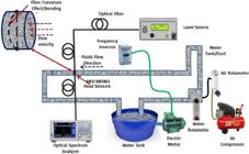
Experimental Setup evaluated for water single-phase measurement and two-phase measurement of water and air using different optical fiber structures of SMS/SNCS/SMSMS on hydraulic system.
The experimental setup was designed to evaluate the sensitivity and performance of five different optical fiber head sensor structures: SMS, SNCS, SMSMS, SMErDMS, and SMDCMS, under single-phase and two-phase flow conditions in a controlled pipeline system. A hydraulic pipeline was configured to circulate water for single-phase flow measurements and air-water mixtures for two-phase flow tests. Flow rates were precisely controlled and monitored through calibrated flow controllers and electronic flow meters for reference.
The various head sensors were installed horizontally across the pipe, enabling the curvature to be created by the drag pressure exerted by the flowing water, which was regulated by the rotameter, as shown in Fig. 3. The water pressure acting on the sensors resulted in a deformation. As the water flow intensifies, the water in the sensor exerts a mechanical stress on the fiber, causing an increase in curvature and thus altering the attenuation of the optical signal.
According to the illustrations in Fig. 4 a real evidence of some essential elements that constituted the experimental apparatus of laboratory bench is presented. It can be seen essential details of how the sensor heads were attached to the flow system, followed by a demonstration of the divisions of the hydraulic system designed to carry out the experiments, where the fluid flow control and measurement equipment’s as well as the interrogation mechanism are included.
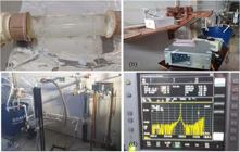
Illustrative images of the real physical setup used in the experiments, having sequentially: (a) Pipe section with head sensors attached (b) Overview of the interrogation system and optical source (c) Water reservoir attached to the control system and flow measurement (d) Optical spectrum analyzer display as interrogation equipment
IV. RESULTS AND DISCUSSION
A highly sensitive flow sensor based on different structures of optical fiber sensor heads was implemented, with sensing areas that varied between singlemode-multimode-singlemode, singlemode-nocore-singlemode, and singlemode-multimode-singlemode-multimode-singlemode. These tests were performed to measure single-phase and two-phase flows in a hydraulic system containing water initially and, afterwards water and air. The fiber was affected by changes in fluid pressure as the flow changed.
The operation of optical fiber head sensors for flow measurement is based on the transduction of mechanical perturbations induced by fluid flow into measurable optical signals through multimodal interference affected by micro-curvature and refractive index changes. The modeling involves three key aspects: mechanical deformation under flow pressure, optical interference modulation, and polarization state control. Mechanical bending induces changes in the propagation constants of the guided modes within the multimode section of the sensor, affecting the modal interference pattern and the interference modifies the transmitted optical power P measured at the output.
For the single-phase flow some measurements were performed, as described as follows. In Fig. 5 (a), it represents the absolute detected power levels at the sensor output, not directly the loss relative to the input. However, changes in these power levels correspond to variations in optical attenuation caused by flow. So it is possible to observe the response of the SMS sensor to the variation of the optical power as a function of the water flow and the polynomial adjustment obtained in the absence and presence of the polarization controller. The Fig. 5 (b) plots optical power (dBm) versus water flow rate (m³/h), it shows a nonlinear, parabolic-like relationship where the parabolic shape of the response curve implies that for certain optical power values, as in e.g., of, -41.85 dBm. The corresponding flow rate is ambiguous, potentially matching two different flow rates of e.g., 1 m³/h or 3 m³/h, which can be solved by creating a multi-dimensional sensing space that uniquely maps to flow rates or apply advanced algorithms that incorporate the full sensor response curve to infer the most probable flow rate given an observed optical power. The parabolic sensor response curve introduces ambiguity in flow rate estimation at certain power levels. Combining multiple sensing parameters, employing additional sensors, or applying advanced signal processing can resolve this ambiguity and improve measurement accuracy.

Response of the sensors for water flow variation measurement. (a) SMS sensor with MMF 5mm. (b) SNCS sensor with 5mm of the NC fiber.
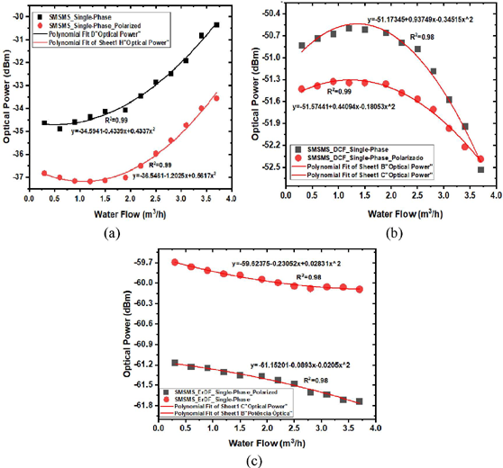
Fig. 6 (a) shows the response of the SMSMS sensor in relation to the water flow. The curves indicate that polynomial corrections were obtained both with and without the polarization controller. The average sensitivity has increased from 0.862 dBm/(h/m³) to 1.122 dBm/(h/m³), which aligns with the utilization of the polarizer. Fig. 6 (b) illustrates the range of response of the SMDCMS structure, which varies from -0.689 dBm/(h/m³) to -3,788 dBm/(h/m³3). On the other hand, Fig. 6 (c) displays the values for the SMErDFMS structure, which range from -0.041 dBm/(h/m³) to -0.409 dBm/(h/m³). Under identical experimental settings with the polarization controller, it was seen that the utilization of polarization control leads to an enhancement in the sensitivity values for all sensors.

Response of the sensors for water flow variation measurement. (a) SMSMS sensor with an SMF of 20mm. (b) SMDCMS sensor with 20mm of DC fiber; and (c) SMErDMS sensor with 20mm of ErD fiber.
To verify the effect of flow measurement based on the bending action which results in the losses that results in the amplitude sensitivity; it was calculated based on the polynomial regression fitting which the data are originated with the values of all the graphs, where it was deduced that the smallest power loss based on bending diameter demonstrated the high sensitivity. So when the fiber is bent from a more flow rate it results in a more power loss out of the fiber where more light interacts with the surround effects and consequently this action results in a sensitivity values improvement. The head sensors showed that they are more sensitive in the low flow values and this behavior was verified for both situations of measurement as single-phase of air and two-phase when air is inserted, so that the sensitivity of the flow with air presence is inserted into the system which have a small values and reduction of determination coefficient and it can be explained that when applied force is lower when the presence of two fluids in the pipe
The average sensitivity reported in this study quantifies the sensor's response to changes in flow rate by relating variations in the optical power signal to volumetric flow changes. To ensure clarity and reproducibility, the following methodology was applied for determining average sensitivity and optical power measurements were recorded continuously at discrete, incremental flow rates spanning the full experimental range, both for single-phase and two-phase flows. For each pair of consecutive measurement points (Qi,Pi) and (Qi+1,Pi+1), a point-by-point sensitivity Si was calculated as the slope of the optical power change relative to the flow change:
Where Pi is the optical power (in dB) at flow volume Qi (in m³/h). r measurements were recorded continuously at discrete, incremental flow rates spanning the full experimental range, both for single-phase and two-phase flows.
For comparison of all the sensors submitted to single-phase measurement, Table I summarizes the values of sensitivity obtained in the two situations: with polarization control and without polarization control.
It was also considered a two-phase flow measurement containing water and air with a maximum flow of 60 liters per minute of fluid.
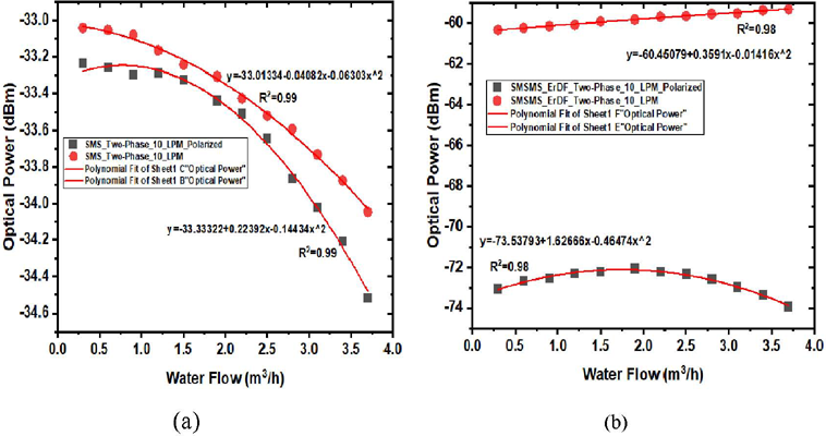
Fig. 7 shows the tests performed under the conditions of two-phase flow measurement of air and water. The polarization control was also applied. As shown in Fig. 7 (a), the SMS sensor average sensitivity changes from -0.126 dB/(m³/h) to -0.288 dB/(m³/h), and in Fig. 6 (b), the SMErDMS sensor average sensitivity varied from -0.028 dB/(m³/h) to -0.929 dB/(m³/h).
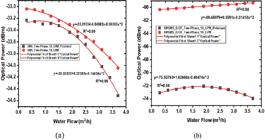
Two-phase flow response of the sensors for water flow variation measurement. (a) SMS sensor and (b) SMErDMS sensor
| Sensor | Non Polarized | Polarized | ||
|---|---|---|---|---|
| Average Sensitivity (dB/(m³/h)) | R2 | Average Sensitivity (dBm/(m³/h)) | R2 | |
| SMS | -0.126 | 0.99 | -0.288 | 0.99 |
| SMErDMS | -0.028 | 0.99 | -0.929 | 0.99 |
In Fig. 8 is presented the approach that compares the initial and final sensitivities, before and after polarization control for SMS, SNCS, SMSMS, SMErDMS, and SMDCMS in (a) for the single-phase measurement tests and, on the other side, SMErDMS and SMS (b) for sensors under both single-phase and two-phase flow conditions, as described in tables III and IV, which present the sensors' average sensitivity compared with the literature.
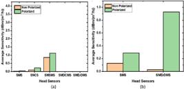
Comparison of Average Sensitivity of Different Optical Fiber Head Sensors in Polarized and Non-polarized conditions: (a) Single-phase sensors tests and (b) Two-phase sensors tests
Our findings show superior or comparable sensitivity enhancements relative to previously reported values, underscoring the efficacy of incorporating erbium-doped fibers and polarization control in the sensor design and conventional SMS sensors typically show modest sensitivity increases under comparable flow conditions, while the SMErDMS configuration leverages multimodal interference combined with erbium doping to substantially increase the measured optical response to flow variations.
The experimental results demonstrate significant improvements in sensor sensitivity, particularly for the SMErDMS structure, which exhibited an approximately 10-fold increase under single-phase flow conditions and an approximately 33-fold increase under two-phase conditions. To place these results in context, Table III summarizes sensitivity values reported in relevant recent literature for similar optical fiber-based flow sensors.
This comparative analysis confirms that the implemented methodologies in this study not only enhance sensitivity magnitude but also improve measurement reliability across complex flow regimes, thereby contributing valuable advancements to optical fiber flow measurement technologies. The sensitivity improvements observed in the SMErDMS and SMS sensor structures against existing literature significantly strengthens the argument for our design’s efficacy, following the application of polarization control, similarly, the SMS sensor sensitivity also improved, albeit with smaller fold changes.
The erbium-doped fiber (ErDF) in the sensor head is not primarily used for amplification purposes in the context of flow measurement. Instead, its inclusion as a sensor head type in this research work leverages the unique optical and material properties of erbium-doped fiber, such as enhanced sensitivity to mechanical perturbations, rather than signal amplification. Any optical gain effect from the erbium-doped fiber in the sensing area is generally minimal or not exploited as amplifier gain; the setup does not include the necessary optical pumping for EDF amplification. Thus, the ErDF head sensor’s role is to explore how doping modifies sensor sensitivity and performance under controlled polarization and flow-induced perturbations, rather than to provide optical amplification.
By benchmarking the sensor sensitivities against typical values reported in the literature, the comparative in table IV clearly demonstrates that the sensor designs, particularly SMDCMS and SMErDMS—achieve superior performance due to advanced fiber architectures and polarization stabilization. The observed fold increases in sensitivity are among the highest reported for optical fiber flow sensors, underscoring the practical and theoretical advances of our work.
This analysis validates the design choices and experimental methodology, establishing a strong argument for the practical deployment of these sensor configurations in industrial pipeline flow measurement systems where sensitivity and reliability are paramount. Across all sensor types, applying polarization control yields consistent sensitivity enhancements. This is achieved by stabilizing modal interference and suppressing polarization mode dispersion and related noise sources, improving the signal-to-noise ratio and enabling detection of subtle flow-induced optical changes. This foundational effect is well-grounded in optical fiber sensor theory and supported by your experimental data.
V. CONCLUSIONS
This research focuses on experimentally measuring single and two-phase water flows generated by micro curvature effects in optical fiber heads. The measurement is accomplished using SMS and SMSMS sensor architectures. The measurement of single and two-phase water flows in a pipeline hydraulic system is achieved by observing the changes in optical power intensity as water flow varies. The measurement is acquired by the influence of curvature in the sensor caused by the pressure applied by the water on the fiber.
The studies conducted using SMS and SMSMS sensors to measure single and two-phase water flows enabled an analysis to assess the influence of polarization control on the measurements. The results showed a notable change in the average sensitivities, suggesting that controlling polarization during sensing operations is essential for managing the effects of birefringence in the fiber and adjusting the optical power between polarization modes.
The average sensitivity of the SMS sensor for single-phase flow increased from 0.027 dBm/(h/m³) to 0.041 dBm/(h/m³), whereas the average sensitivity of the SNCS structure ranged from 0.093 dBm/(h/m³) to 0.221 dBm/(h/m³). The average sensitivity of the SMSMS sensor increased from 0.862 dBm/(h/m³) to 1.122 dBm/(h/m³). Similarly, the average sensitivity of the SMErDMS structure decreased from -0.041 dBm/(h/m³) to -0.409 dBm/(h/m³). Lastly, the average sensitivity of the SMDCMS structure varied from -0.689 dBm/(h/m³) to -3,788 dBm/(h/m³).
Additional tests were conducted using the same experimental settings to examine the impact of the polarization controller on the two-phase flow. The tests were carried out at a maximum flow rate of 60 liters per minute. The findings exhibited a consistent pattern. Additionally, there was a discrepancy in the mean sensitivity levels. The SMS sensor has a range of -0.126 dBm/(h/m³) to -0.288 dBm/(h/m³), whereas the SMErDMS has a range of -0.028 dBm/(h/m³) to -0.929 dBm/(h/m³). These ranges apply when the polarization controller is not used.
The two-phase flow sensor demonstrated excellent repeatability and a fast time response was inferred from sensor design characteristics that suggest this behavior is supported by literature values of similar sensor configurations, which confirms that it can potentially be applied to monitoring pipelines. Comparative analysis in terms of the performance of optical sensors used in flow measurements in pipelines shows that structure as the SMSMS fiber sensor can offer higher sensitivity and a wider dynamic range than the SMS like fiber sensors due to their more complex structures. However, the SMS and SNCS sensors have simpler structures and can be easier to manufacture and integrate into existing systems. Upon examination of the results presented in the paper focus was primarily on sensitivity, optical power variations, flow rate calibration, and spectral analysis, but do not include transient or dynamic response measurements such as rise time, settling time, or temporal resolution. The response time is inferred from sensor design characteristics supported with literature values of similar sensor configurations, and no explicit experiments concerning response time are presented in the results section.
The theoretical novelty of the research lies in the convergence of three innovations in the specific main advantages, like core diameter mismatch as a sensitivity-amplifying geometric feature; polarization engineering to suppress noise and cross-sensitivities; and multimodal interference decoding for multiphase flow discrimination. Head sensors refer to the specifically engineered section of an optical fiber sensor system that is directly exposed to the physical quantity being measured and in this case, the fluids flow inside a pipeline.
In the context of this work, the head sensor is the portion of the optical fiber assembly where the sensing structure is fabricated, such as the region where single-mode, multimode, no-core, or specialty fibers are spliced or arranged to form configurations like SMS, SMSMS, SNCS, SMErDFMS, or SMDCFMS. The head sensor is the active sensing element that interacts with the environment (e.g., flow, pressure, temperature) and transduces these physical changes into measurable optical signals (such as intensity, wavelength shift, or phase change). This framework advances optical fiber sensors beyond conventional strain/temperature monitoring, enabling high-fidelity flow measurement in industrial pipelines transitioning from passive strain/temperature detection to intelligent flow signature analysis for industrial applications. The authors clarify that polarization control is critical for accuracy in dynamic environments, establishing a new design paradigm for interference-based fiber sensors.
Practically, this work provided a clear pathway for enhancing optical fiber flow sensors in industrial pipeline monitoring, where precise and stable measurements under complex flow regimes are imperative. The incorporation of polarization control and tailored fiber sensor heads equips these systems with improved resolution and reduced noise, enabling more accurate detection of flow variations. This advancement supports real-time pipeline diagnostics, leak detection, and multiphase flow management that are critically needed in oil, gas, and water distribution infrastructures.
This study demonstrates significant enhancements in the sensitivity of optical fiber head sensors for flow measurement in pipelines by employing controlled polarization and advanced sensor structures, including erbium-doped fiber configurations (SMErDMS). Among the five sensor architectures tested, the SMErDMS sensor achieved up to a 10-fold increase in average sensitivity for single-phase flow and a 33-fold improvement under two-phase flow conditions compared to non-polarized configurations and these improvements result from the combined effects of multimodal interference, polarization stabilization, and the unique optical properties of erbium-doped fibers.
The average sensitivities were rigorously calculated from point-by-point increments across experimental flow rates, ensuring a robust characterization of sensor response. The polynomial fitting confirmed high linearity with coefficients of determination above 0.98, underscoring measurement reliability. Future work may extend this approach to distributed sensing arrays and incorporate dynamic environmental compensation, further strengthening the applicability of these optical sensor designs in demanding industrial settings.
ACKNOWLEDGMENT
This research is carried out under the financial support by the Brazilian Funding Agencies CAPES and CNPq, under the auspices of the Laboratory of Applied Electromagnetism (LEA) of the Federal University of Pará (UFPA) and the direct collaboration of Military Institute of Engineering (IME). And on the other hand, collaboratively with the Rovuma University (UniRovuma).
DATA AVAILABILITY
The data that support the findings of this study are available from the corresponding author, Sualehe, I.S.V., upon reasonable request.
REFERENCES
-
1 K. A. Volkov, M.l V. Dashkov, “Investigation of the Polarization Characteristics of Brillouin Scattering”, Proceedings SPIE Optical Technologies for Telecommunications 2018, vol.1116, pp. e111461O:1 – e111461O:7, 2019. DOI: 10.1117/12.2527572.
» https://doi.org/10.1117/12.2527572. -
2 M. R. Ridho, D. N. Sari, P. Prasintha, U. Z. Fikroh, M. Yasin, H. Trilaksana, and Samian, "Liquid Level Sensor Using U-Bent SMS Fiber Structure”, AIP Conference Proceedings, vol. 2314, pp. e030008:1 – e030008:6, 2020. DOI:10.1063/5.0034551.
» https://doi.org/10.1063/5.0034551 -
3 Y. Zhao, L. Cai, X-G. Li, F-C. Meng, and Z. Zhao, "Investigation of the High Sensitivity RI Sensor Based on SMS Fiber Structure”, Sensors, and Actuators, A, vol. 205, pp. 186-190, 2014. DOI: 10.1016/j.sna.2013.11.008.
» https://doi.org/10.1016/j.sna.2013.11.008. -
4 G. Bawa, K. Dandapat, G. Kumar, I. Kumar, & S. M. Tripathi, “Single-Multi-Single Mode Fiber Optic Structure-Based Water Depth Sensor”, IEEE Sensors Journal, vol. 19, No. 16, pp. 6756-662, 2019. DOI: 10.1109/JSEN.2019.2915680
» https://doi.org/10.1109/JSEN.2019.2915680 -
5 I. Del Villar, J. Goñi, A. Vicente, F. J. Arregui, and I. R. Matias, “Multimode Fiber Length Dependence on Spectral Properties and Sensitivity of Single-multi-single Mode (SMS) Fiber Combination”, Journal of Lightwave Technology, vol. 37, no. 18, pp. 1-11, 2019. DOI: 10.1109/JLT.2019.2922540.
» https://doi.org/10.1109/JLT.2019.2922540. -
6 P. Prasintha, D. N. Sari, M. R. Ridho, U. Z. Fikroh, Pujiyanto, H. Trilaksana and Samian, “Detection of Lubricating Oil Viscosity Based on Displacement Sensor using Fiber Coupler and Concave Mirror”, The 2nd International Conference on Physical Instrumentation and Advanced Materials 2019, AIP Conferences. Proceedings vol. 2314, pp. e030010:1–e030010:7, 2020. DOI: 10.1063/5.0034554.
» https://doi.org/10.1063/5.0034554. -
7 J. Zhang, Z. Lian, Z. Zhou, J. Zhang, M. Xiong and J. Liu, “Numerical and Experimental Study on Leakage Detection for Buried Gas Pipelines Based on Distributed Optical Fiber Acoustic Wave”, Measurement Science and Technology vol. 32, no.125209, pp. e125209:1 – e125209:15, 2021. DOI: 10.1088/1361-6501/ac2d3e.
» https://doi.org/10.1088/1361-6501/ac2d3e. -
8 H. Li, H. Li, F. Meng, X. Lou and L. Zhu, “All-fiber MZI Sensor Based on Seven-core Fiber and Fiber Ball Symmetrical Structure”, Optical and Laser in Engineering, vol. 112, pp. 1–6, 2019. DOI: 10.1016/j.optlaseng.2018.08.021.
» https://doi.org/10.1016/j.optlaseng.2018.08.021. -
9 H. Di, Y. Xin, and J. Jian, “Review of optical fiber sensors for deformation measurement”, Optik, vol. 168, no. 20, pp. 703-713, 2018. DOI: 10.1016/j.ijleo.2018.04.131.
» https://doi.org/10.1016/j.ijleo.2018.04.131. -
10 V. H. R. Cardoso, F. M. Takeda, C. S. Fernandes, M. T. R. M. Giraldi, J. C. W. A. Costa, “Mach-Zehnder Interferometer Based on Core Diameter Mismatch Structures for Curvature Measurement”; SBMO/IEEE MTT-S International Microwave and Optoelectronics Conference (IMOC), IEEE 2019. DOI: 10.1109/IMOC43827.2019.9317576.
» https://doi.org/10.1109/IMOC43827.2019.9317576 - 11 X. Zhang, J. Kang, S. Yin, J. Yang, “In-line MZI Interferometer for Liquid Level Measurement Based on Cascaded SMS and MSM Structure”, Asia Communications and Photonics Conference (ACP), 2019.
-
12 H. Ahmad, M. M. Hayat, M. Z. A. Razak, & M. S. A. Aziz, “Core diameter mismatched multi-mode interference fiber optic sensor for detection of oil adulteration”. Optics & Laser Technology, vol. 140, no. 107143, pp. 107143-1 – 107143-6, 2021. DOI: 10.1016/j.optlastec.2021.107143.
» https://doi.org/10.1016/j.optlastec.2021.107143 -
13 S. Kharunya, S. Swapna, & S. Jinesh, “Modal interferometer based on core diameter mismatch for strain sensing applications”, Optical Fiber Technology, vol. 64, no. 102610, pp. 102610-1 – 102610-6, 2021. DOI: 10.1016/j.yofte.2021.102610.
» https://doi.org/10.1016/j.yofte.2021.102610. -
14 Y. W. Huang, J. Tao and X. G. Huang, “Research Progress on F-P Interference—Based Fiber-Optic Sensors”, Sensors, vol. 16, no. 1424, pp. 5142-5149, 2016. DOI: 10.3390/s16091424.
» https://doi.org/10.3390/s16091424 -
15 S. He, Y. Xu, D. Liu, B. Dong, & X. Qiao, “Temperature sensor based on a multimode interference structure with core diameter mismatch”, Applied Optics, vol. 60, no. 4, pp. 1029-1034, 2021. DOI: 10.1364/AO.415982.
» https://doi.org/10.1364/AO.415982. - 16 N. F. Noori, T. S. Mansour, “Control of gas pipeline leakage detection based on hybrid inline fiber interferometer”, Indonesian Journal of Electrical Engineering and Computer Science, vol. 30, no. 2, pp. 748-759, 2023.
-
17 Y. Fang, Y. Guo, J. Li, & M. Zhang, “High-sensitivity refractive index sensor based on a core diameter mismatched multi-mode interference structure”, Optics Communications, vol. 497, no. 126027, pp. 126027-1 – 126027-6, 2021. DOI: 10.1016/j.optcom.2021.126027.
» https://doi.org/10.1016/j.optcom.2021.126027. -
18 V. H. R. Cardoso, M. T. M. R. Giraldi, C. S. Fernandes, M. O. Silva, and J. C. W. A. Costa, “A Simple Optical Sensor Based on an In-Line Mach–Zehnder Interferometer for Monitoring Single and Two-Phase Flows in Pipelines”, IEEE Transactions on Instrumentations and Measurement, vol. 70, pp. 1-6, 2021. DOI: 10.1109/TIM.2021.3070640.
» https://doi.org/10.1109/TIM.2021.3070640. - 19 I. S. V. Sualehe, V. H. R. Cardoso, M. T. M. R. Giraldi, M. O. Silva, J. C. W. A. Costa, “Monoflow Measurement with Polarization Controlled Effect in SMS-SMSMS Optical Fiber Sensors Based on Core Diameter Mismatch Technique”, International Microwave and Optoelectronic Conference – IMOC, SBMO/IEE MTT-S, São Caetano do Sul: SBMO, vol. 1. pp. 159-162, 2023.
-
20 L. G. P. K. Chaganti, M. H. Ahmad, M. A. M. Piah, M. Y. M. Noor, and Azmi, A. I. “Fiber Optic Acoustic Sensor Based on SMS Structure With Thin Polymer Diaphragm for Partial Discharge Detection”; IEEE Photonics Journal, vol 8, pp. 188044-188055, 2020. DOI: 10.1109/JPHOT.2020.3022170.
» https://doi.org/10.1109/JPHOT.2020.3022170 -
21 K. S. Ong, W. H. Png, H. S. Lin, C. H. Pua and F. A. Rahman, “Acoustic Vibration Sensor Based on Macro-Bend Coated Fiber For Pipeline Leakage Detection”, 17th International Conference on Control, Automation and Systems (ICCAS 2017), pp. 167-171, 2017. DOI: 10.23919/ICCAS.2017.8204436
» https://doi.org/10.23919/ICCAS.2017.8204436 -
22 K. Wang, X. Dong, M. H. Köhler, P. Kienle, Q. Bian, M. Jakobi, and A. W. Koch, “Advances in Optical Fiber Sensors Based on Multimode Interference (MMI): A Review”, IEEE Sensors Journal, vol. 21, no. 1, pp. 132-142, 2021. DOI: 10.1109/JSEN.2020.3015086.
» https://doi.org/10.1109/JSEN.2020.3015086. -
23 M. Olivero, A. Vallan, R. Orta, & G. Perrone, “Single-Mode–Multimode–Single-Mode Optical Fiber Sensing Structure With Quasi-Two-Mode Fibers”. IEEE Transactions on Instrumentation and Measurement, vol. 67, no. 5, pp. 1223–1229, 2018. DOI: 10.1109/TIM.2018.2799078.
» https://doi.org/10.1109/TIM.2018.2799078 -
24 R. Oliveira1, S. Aristilde, J. H Osório, M. A. R. Franco, L. Bilro, R. N. Nogueira and C. M. B. Cordeiro, “Intensity Liquid Level Sensor Based on Multimode Interference and Fiber Bragg Grating”, Measurement Science and Technology, vol. 17, no. 125104, pp. 125104-1 – 125104-6, 2016. DOI: 10.1088/0957-0233/27/12/125104.
» https://doi.org/10.1088/0957-0233/27/12/125104 -
25 R. Petrearce, C. Rascon & G. E. Sandoval-Romero, “Design and Implementation of an Acoustic Wave Measuring System Based on a Fiber Optic Sensor Using Multimodal Interference”, Journal of Electromagnetic Waves and Applications, vol 36, no. 14, pp. 2010-2026, 2022. DOI: 10.1080/09205071.2022.2063580.
» https://doi.org/10.1080/09205071.2022.2063580. -
26 Q. Wu, Y. Qu, J. Liu, J-H. Yuan, S-P. Wan, T. Wu, X-D. He, B. Liu, D. Liu, Y. Ma, Y. Semenova, P. Wang, X. Xin, and G. Farrell, “Singlemode-Multimode-Singlemode Fiber Structures for Sensing Applications – A Review”, IEEE Sensors Journal, vol. 21, no. 99:1-1, pp. 12734-12751, 2020. DOI: 10.1109/JSEN.2020.3015086.
» https://doi.org/10.1109/JSEN.2020.3015086. -
27 Z, Wen, Z. Guan, J. Dong, H. Li, Y. Cai, and S. Gao, “A Review of Sensitivity Enhancement in Interferometer-Based Fiber Sensors”, Sensors, vol. 22, no. 2506, pp. 2506-1 – 2506-13, 2022. DOI: 10.3390/s22072506.
» https://doi.org/10.3390/s22072506. -
28 X. P. Zhang, L. X. Li, X. H. Zou, B. Lou, W. Pan, L. S. Yan, and Q. Wu, “Angled Fiber-based Fabry-Perot Interferometer”, Optics Letters, vol. 45, no. 2, pp. 292-295, 2020. DOI: 10.1364/OL.380358.
» https://doi.org/10.1364/OL.380358. -
29 W. Lyu, S. Chen, F. Tan, C. Yu, “Vital Signs Monitoring Based on Interferometric Fiber Optic Sensors“, Photonics, vol. 9, no. 2, pp. 1-18, 2022. DOI: 10.3390/photonics9020050.
» https://doi.org/10.3390/photonics9020050 -
30 M. Naora, S. Taue, and H. Fukano, “Ultrasensitive Fiber-optic Refractive Index Sensor Based on Multimode Interference with Fiber-Loop Configuration”, 22nd Microoptics Conference-MOC, IEEE Inc. Japanese, Journal of Applied Physics vol. 57, no. 8, pp. 6076-6080, 2004. DOI: 10.7567/JJAP.57.08JC01.
» https://doi.org/10.7567/JJAP.57.08JC01 -
31 N. Lalam, B. Grainger, P. Ohodnicki, M. P. Buric, R. Wright, "Field-Testing of Water Pipeline Flow Monitoring Based on SMS Fiber Optic Acoustic Sensor," Proc. SPIE 12532, Optical Waveguide and Laser Sensors II, vol. 12532, pp. e125320Q:1 – e125320Q:6, 2023. DOI: 10.1117/12.2663289.
» https://doi.org/10.1117/12.2663289. -
32 H. Fu, N. Zhao, M. Shao, H. Li, H. Gao, Q. Liu, Z. Yong, Y. Liu, and X. Qiao, “High-Sensitivity Mach-Zehnder Interferometric Curvature Fiber Sensor Based on Thin-Core Fiber”, IEEE Sensors Journal, vol. 15, no. 1, pp. 503-509, 2015. DOI: 10.1109/JSEN.2014.2369071.
» https://doi.org/10.1109/JSEN.2014.2369071. -
33 A. Kumar, N. N. S. Ojha, N. Kumar, “Highly Sensitive Single-fiber MZI Configuration for Weight Sensing”, Optics and Laser Technology vol. 130, no. 10633, pp. e10633:1–e10633:8, 2020. DOI: 10.1016/j.optlastec.2020.106334.
» https://doi.org/10.1016/j.optlastec.2020.106334. -
34 S. Silva, O. Frazão, “Multimode Interference-based Fiber Sensor in a Cavity Ring-down System for Refractive Index Measurement”, Optics & Laser Technology, vol. 91, pp. 112–115, 2017. DOI: 10.1016/j.optlastec.2017.01.017.
» https://doi.org/10.1016/j.optlastec.2017.01.017. -
35 A. Yu, F. Pang, Y. Yuan, Y. Huang, S. Li, S. Yu, M. Zhou, L. Xia, “Simultaneous Current and Vibration Measurement Based on Interferometric Fiber Optic Sensor”, Optics and Laser Technology, vol. 161, no. 109223, pp. e109223:1 – e e109223:8, 2023. DOI: 10.1016/j.optlastec.2023.109223.
» https://doi.org/10.1016/j.optlastec.2023.109223. -
36 J. Gong, C. Shen, Y. Xiao, S. Liu, C. Zhang, Z. Ding, H. Deng, J. Fang, T. Lang, C. Zhao, Y. Chen, “High sensitivity Fiber Temperature Sensor Based PDMS Film on Mach-Zehnder Interferometer”, Optical Fiber Technology, vol. 53, no. 102029, pp. e102029:1 – e102029:4, 2019. https://doi.org/10.1016/j.yofte.2019.102029
» https://doi.org/10.1016/j.yofte.2019.102029 -
37 P. Wang, H. Zhao, X. Wang, G. Farrell and G. Brambilla, “A Review of Multimode Interference in Tapered Optical Fibers and Related Applications”, Sensors, vol. 18, no. 858, pp. e858:1 – e858:20, 2018. DOI: 10.3390/s18030858
» https://doi.org/10.3390/s18030858 -
38 Q. Wang, Y. Liu, “Review of Optical Fiber Bending/curvature Sensor”, Measurement, vol. 130, pp. 161-172, 2018. DOI: 10.1016/j.measurement.2018.07.017.
» https://doi.org/10.1016/j.measurement.2018.07.017. -
39 A. M. Hatta, K. Indriawati, T. Bestariyan, T. Humada, and Sekartedjo, “SMS Fiber Structure for Temperature Measurement Using an OTDR”, Photonic Sensors, vol. 3, no. 3, pp. 262-266, 2013. DOI: 10.1007/s13320-013-0104-9
» https://doi.org/10.1007/s13320-013-0104-9 -
40 H.A. Razak, N.H. Sulaiman, H. Haroon, Z. A.S. Mohd, “A Fiber Optic Sensor Based on Mach-Zehnder Interferometer Structure for Food Composition Detection”. Microwave and Optical Technology Letters, vol. 60, pp. 920–925, 2018. DOI: 10.1002/mop.31156.
» https://doi.org/10.1002/mop.31156 -
41 V. Bhardwaja, K. Kishorb, A. C. Sharma, “Tapered Optical Fiber Geometries and Sensing Applications Based on MachZehnder Interferometer: A Review”, Optical Fiber Technology vol. 58, no. 102302, pp. e102302:1 – e102302:12, 2020. DOI: 10.1016/j.yofte.2020.102302.
» https://doi.org/10.1016/j.yofte.2020.102302. -
42 J. H. Osorio, W. M. Guimaraes, L. Peng, M. A.R. Franco, S. C. Warren-Smith, H. Ebendorff-Heidepriem, C. M. B. Cordeiro, “Exposed-core Fiber Multimode Interference Sensor”, Results in Optics, vol. 5, no. 100125, pp. 100125-1 – 100125-7, 2021. DOI: 10.1016/j.rio.2021.100125.
» https://doi.org/10.1016/j.rio.2021.100125 -
43 A. Miliou, “In-Fiber Interferometric-Based Sensors: Overview and Recent Advances”. Photonics, vol. 8, no. 265, pp. 265-1 – 265-20, 2021. DOI: 10.3390/photonics8080265.
» https://doi.org/10.3390/photonics8080265 -
44 Y. Ning, Y. Zhang, H. Guo, M. Zhang, Y; Zhang, S. Li, Z. Liu, J. Zhang, X. Yang, and L. Yuan, “Optical Fiber Magnetic Field Sensor Based on Silk Fibroin Hydrogel”, IEEE Sensors Journal, vol. 22, No. 15, pp. 14878-14882, 2022. DOI: 10.1109/JSEN.2022.3179078.
» https://doi.org/10.1109/JSEN.2022.3179078. -
45 V. H. R. Cardoso, P. Caldas, M. T. R. Giraldi, C. S. Fernandes, O. Frazão, J. C. W. A. Costa, and J. L. Santos, “A Simple Optical Sensor Based on Multimodal Interference Superimposed on Additive Manufacturing for Diameter Measurement”, Sensors, vol. 22, no. 4560, pp. e4560:1–e4560:15, 2022. DOI: 10.3390/s22124560.
» https://doi.org/10.3390/s22124560. -
46 Y. Zhao, J. Zhao, and Q. Zhao, “High Sensitivity Seawater Temperature Sensor Based on No-core Optical Fiber”, Optical Fiber Technology, vol 54, no. 102115, pp. e102115:1–e102115:6, 2020. DOI: 10.1016/j.yofte.2019.102115.
» https://doi.org/10.1016/j.yofte.2019.102115. -
47 D. Yi, Z. Huo, Y. Geng, X. Li, and X. Hong, “PMDS-coated no-core Fiber Interferometer With Enhanced Sensitivity for Temperature Monitoring Applications”, Optical Fiber Technology, vol. 57, no. 102185, pp. e102185:1–e102185:5, 2020. DOI: 10.1016/j.yofte.2020.102185.
» https://doi.org/10.1016/j.yofte.2020.102185. -
48 Z. Wanga, D. Chena, X. Yanga, S. Liang, J. Wanga, and X. Sun, “Temperature Sensing Characteristics of Improved SNCS Fiber Sensor”, Instruments and Experimental Techniques, vol. 65, no. 6, pp. 957–965, 2022. DOI: 10.1134/S0020441222060040.
» https://doi.org/10.1134/S0020441222060040. -
49 A. Miliou, “In-Fiber Interferometric-Based Sensors: Overview and Recent Advances”, Photonics, vol. 8, no. 265, pp. 1-22, 2021. DOI: 10.3390/photonics8080265.
» https://doi.org/10.3390/photonics8080265. -
50 S. Gerami, M. K. M. Farshi, “Analysis of Multimode Interference in a Fabricated Fiber Optic Refractive Index Sensor”, 28th Iranian Conference on Electrical Engineering (ICEE), pp. 978-1-7281-7296-5, 2020. DOI: 10.1109/ICEE49607.2020.9266791.
» https://doi.org/10.1109/ICEE49607.2020.9266791. -
51 X. Sun, H. Du, X. Dong, Y. Hu, and J. Duan, “Simultaneous Curvature and Temperature Sensing Based on a Novel Mach-Zehnder Interferometer”; Photonic Sensors, vol. 10, no. 2, pp. 171‒180, 2020. DOI: 10.1007/s13320-020-0701-2
» https://doi.org/10.1007/s13320-020-0701-2 -
52 J. W. Costa, M. A. R. Franco, V. A. Serrão, C. M. B. Cordeiro, and M. T. R. Giraldi, “Macrobending SMS fiber-optic Anemometer and Flow Sensor”, Optical Fiber Technology, vol. 52, no. 101981, pp. 101981-1 – 101981-9, 2019. DOI: 10.1016/j.yofte.2019.101981.
» https://doi.org/10.1016/j.yofte.2019.101981 -
53 M. Enggholm, K. Hammarling, H. Anderson, M. Sandberg, H-E. Nilsson, “A Bio-Compatible Fiber Optic pH Sensor Based on a Thin Core Interferometric Technique”, Photonics, vol. 6, no. 11, pp. 1-12, 2019. DOI: 10.3390/photonics6010011.
» https://doi.org/10.3390/photonics6010011. -
54 Z. Wang, D.L. Chen, XC. Yang, SX. Liang, XH. Sun, “Temperature Sensor of Single-mode-no-core-single-mode Fiber Structure Coated with PDMS”, Optical Fiber Technology, vol. 68, no. 102793, pp. e102793:1 – e102793:5, 2022. DOI: 10.1016/j.yofte.2022.102793.
» https://doi.org/10.1016/j.yofte.2022.102793. -
55 J. Zhao, J. Xu, C. Wang, Y. Liu, and Z. Yang, “Experimental Demonstration of Multi-parameter Sensing Based on Polarized Interference of Polarization-maintaining Few-mode Fibers”, Optics Express, vol. 28, no. 14, pp. 20372-20378, 2020. DOI: 10.1364/OE.394358.
» https://doi.org/10.1364/OE.394358. -
56 Y. Ma, X. Qiao, T. Guo, Z. Feng, J. Zhang, Y. Weng, Q. Rong, and M. Hu, et al., “Mach–Zehnder Interferometer Based on a Sandwich Fiber Structure for Refractive Index Measurement”, IEEE Sensors Journal, vol 12, no. 6, pp. 2081-2085, 2012. DOI: 10.1109/JSEN.2012.2189070.
» https://doi.org/10.1109/JSEN.2012.2189070. -
57 O. H. Unalmis, “A Methodology for In-Well Multiphase Flow Measurement with Strategically Positioned Local and/or Distributed Acoustic Sensors”, Sensors, vol. 23, no. 13, pp. 1-20, 2023. DOI: 10.3390/s23137256.
» https://doi.org/10.3390/s23137256. -
58 C. Caucheteur, T. Guo, and J. Albert, “Polarization-Assisted Fiber Bragg Grating Sensors: Tutorial and Review”, Journal of Light Technology, vol. 35, no. 16, pp. 1-18, 2017. DOI: 10.1109/JLT.2017.2709079.
» https://doi.org/10.1109/JLT.2017.2709079. - 59 M. M. A. Eid, “Optical Fiber Sensors: Review of Technology and Applications”, Indonesian Journal of Electrical Engineering and Computer Science, vol. 25, no. 2, pp. 1038-1046, 2022.
-
60 R. Wang, K. Tian, M. Zhang, Y. Jiang, L. Yuan, G. Jin, G. Farrell, Lewis, E. and Wang, P., “Investigation on the Polarization Dependence of An Angled Polished Multimode Fibre Structure”, Journal of Lightwave Technology, vol. 38, no. 16, pp.4520-4525, 2020. DOI: 10.11591/ijeecs.v25.i2.1038-1046
» https://doi.org/10.11591/ijeecs.v25.i2.1038-1046 -
61 A. Mecozzi, M. Cantono, J. Castellanos, V. Kamalov, R. Muller and Z. Zhan, “Polarization Sensing Using Submarine Optical Cables”, Optica, vol. 8, no. 6, pp. 788-795, 2021. DOI: 10.1364/OPTICA.418358
» https://doi.org/10.1364/OPTICA.418358 -
62 Z. Vyležich, M. Kyselák, “Utilization of Telecommunication Optical Routes to Power Fiber-optic Polarization Sensors”, Optica Applicata, vol. 52, no. 4, pp. 565-574, 2022. DOI: 10.5277/oa220401.
» https://doi.org/10.5277/oa220401. -
63 Y. Meng, Y. Hao, L. Luo, and J. Li, “Birefringence of Single Polarization for Flexural-Wave Metamaterials”, Physical Review Applied vol. 18, no. 064073, pp. e064073:1 – e064073:6 , 2022. DOI: 10.1103/PhysRevApplied.18.064073.
» https://doi.org/10.1103/PhysRevApplied.18.064073. -
64 L. Xiao, Y. Wang, Y. Li, Q. Bai, X. Liu, and B. Jin, “Polarization Fading Suppression for Optical Fiber Sensing: A Review”, IEEE Sensors Journal, vol. 22, no. 9, pp. 8295–8311, 2022. DOI: 10.1103/PhysRevApplied.18.064073. DOI: 10.1109/JSEN.2022.3140192.
» https://doi.org/10.1103/PhysRevApplied.18.064073. DOI: 10.1109/JSEN.2022.3140192.
-
Editor:
Carlos E. Capovilla
-
Associate Editor:
Danilo H. Spadoti