Compact Top-Loaded Quarter-Cylinder Dielectric Resonator Antenna
Abstract
This article presents the design of a top-loaded quartercylinder dielectric resonator antenna (TL-QCDRA). The approach to reduce the antenna dimensions is based on the use of E and H-walls to impose Dirichlet and Neumann boundary conditions to the fields inside the dielectric resonator. The proposed antenna was modeled and optimized with the electromagnetic simulator ANSYS HFSS and was designed to operate at 1.575 GHz (L1- band of the global positioning system - GPS). The excitation is achieved by a coaxial probe along with a series inductor, whichis used to compensate the capacitive input reactance. A prototype was manufactured and measured in an anechoic chamber and good agreement was obtained between numerical and experimental results. In comparison to previously published papers, the proposed design yields higher compactness, which is an important feature for space applications.
Index Terms
Antenna design; Compactness DRA; Dielectric resonator antennas; GNSS antennas.
I. INTRODUCTION
In recent years, the interest on low-weight and compact antennas has been increased due to countless wireless applications with portable equipment, such as wideband applications [1]-[3], wideband MIMO systems [4], aerospace telemetry [5], radio-frequency energy harvesting (RFEH) [6], compact GNSS receivers [7], digital video broadcasting-handheld (DVB-H) and global system for mobile communications (GSM) [8]. An antenna type that fulfills these requirements is the dielectric resonator antenna (DRA), which is composed of a high-permittivity dielectric placed on a ground plane (GND). Currently, the development of DRAs aims at design strategies to meet the compactness requirements whilst keeping the antenna efficiency high. The DRA dimensions can be reduced by increasing the dielectric constant ɛr. However, this yields larger Q-factor and narrow operation bandwidth.
An alternative method to achieve compactness is based on the symmetric distribution of the electromagnetic fields that are established in DRAs with canonical shapes, such as the case of a cylindrical DRA. The use of Dirichlet and Neumann conditions allows placing electrical (E) and magnetic (H) walls inside the cavity without affecting the field distribution [9]. Since this is based on the natureof the excited modes inside the antenna, the walls must be positioned so as to avoid disturbing the original field distribution. Magnetic walls can be synthesized by an abrupt change in dielectric constant. This is the typical case of designing DRAs employing materials with high dielectric constant. On the other hand, E-walls may be implemented by means of metallic plates. The volume of the rectangular (RDRA) [10] or cylindrical dielectric resonator antenna (CDRA) [11], [12] can be reduced roughly by half with the use of one wall (E or H) or by 75% by combining both E and H-walls at the proper symmetry planes of the cylindrical cavity [9], [13].
In [9], [14], a series of analyses for sector DRAs have been carried out. In [14], the authors investigated how the aspect ratio (i.e., radius-to-height ratio) increases the axial ratio bandwidth and how the polarization state behavior varies with the feed position. In [15], an RDRA loaded with a metasurface (MS) and a pair of short-circuited E-walls was proposed. The MS was employed to reduce the overall antenna size and its presence generates a TM surface wave that is excited to create additional resonance above the fundamental mode (TE111) of the RDRA. Additionally, electric walls were inserted to reallocate the two resonant frequencies for the desired broadband performance. In [3], [5], quartercylindrical dielectric resonator antenna (QCDRA) designs using different approaches were reported. While in the former, the QCDRA was composed only of lateral magnetic walls, the latter employs a combination of E and H-walls.
Another size-reduction technique consists in adding a conductor layer on top of the rectangular or cylindrical DRA [16]. This is achieved because the metallic top loading allows exciting modes with vanishing wavenumber along the axial direction. In [17], a dual-fed top-loaded CDRA is proposed.The radius of the top conducting disk provides additional tuning possibility to the design process [18], [19].
In this letter, a modification of the design described in [16] along with the technique presented in [9], [14] is proposed. Due to the difficulty to implement vertical conducting walls using standard printedcircuit board (PCB) techniques and due to the possibility to drill holes precisely in microwave laminates with standard PCB techniques, the E-wall has been implemented with metallic vias. Impedance matching is improved by adding a series inductor onto the antenna. This letter is organized as follows: section II presents the necessary theoretical background to achieve size-reduction. The antenna design applied for a GPS antenna is described in section III. Experimental validation is presented in section IV. Finally, the conclusions are drawn in section V.
II. THEORICAL BACKGROUND
The proposed antenna is derived from a top-loaded cylindrical dielectric resonator antenna (TLCDRA) and its main parameters are height h, radius a and dielectric constant ɛr. The TL-CDRA geometry is shown in Fig. 1(a). It is composed of a low-loss microwave laminate with large ɛr thatis glued onto a square ground plane (GND). The antenna is excited by a coaxial probe, whereby the outer part of the coaxial connector is soldered to the GND and the inner conductor is connected to the top of the antenna.

(a) Geometry of a TL-CDRA; (b) Magnetic field configuration in the cylindrical cavity of the TL-CDRA; (c) Final antenna geometry.
The approach to achieve antenna compactness is based on the field configuration excited in the
cylindrical resonator. Considering that the dielectric cylinder is homogeneous, isotropic and electrically thin (h << λ, where and λ0 is the wavelength in free space at the design frequency), an approximate solution for the fields inside the dielectric can be obtained using the cavity model, which treats the TL-CDRA as a cavity bounded by an H-wall along the lateral (curved) surface and E-walls on the top and bottom. If the condition h << λ can be assumed, then Eρ and Eϕ vanish and the only existing electric field component inside the cavity is Ez, which can be expressed by
for the mn-th mode. This expression can be determined by imposing the boundary conditions cited above, with the indexes m and n denoting the variation of the fields in the cavity along ϕ and ρ, respectively, and E0mnis the electric field magnitude related to the mn-th mode. The constant χ′mn stands for the n-th zero of the derivative of the Bessel function of the first kind and order m, and νm = m for a complete cylinder (i.e. without walls limiting the cavity along ϕ). The nonzero magnetic field components are Hρ and Hϕ, hence the only modes allowed to exist are the TMzmn whilst the condition h << λ is fulfilled.
Fig. 1(b) shows the magnetic field lines established inside the cylindrical cavity for the fundamental mode TMz11. The two symmetry planes are indicated by and . In the former, the magnetic field lines exhibit normal orientation, whereas they are tangential to the latter. According to the Neumann boundary condition, an H-wall can be inserted along the plane without disturbing the original H-field configuration. According to the Dirichlet boundary condition, an E-wall can be inserted in the location of the plane . By doing so, only one quarter-cylinder can be used to generate an equivalent dielectric resonator antenna with an E-wall in the yz-plane and an H-wall in the xz-plane without changing the original field distribution. The resulting geometry is depicted in Fig. 1(c).
For the case of the top-loaded quarter-cylinder dielectric resonator antenna (TL-QCDRA), the wavenumber along ϕ turns to be νm = (2m - 1) [20]. For the fundamental mode TMz11, the electric field inside the quarter-cylinder cavity is given by
with χ′11 = 1.8412. The separation equation leads to an expression for the resonance frequency of the TMz11 mode as a function of the cavity radius, which is given by
where µ and ɛ are the magnetic permeability and the electric permittivity of the dielectric resonator antenna, respectively. By isolating the cylinder radius, it becomes that
which is the basic equation that can be used to calculate the radius of the dielectric cavity for the desired frequency.
III. ANTENNA DESIGN APPROACH
To demonstrate the proposed design strategy, a TL-QCDRA for operation at 1.575 GHz (L1/E1-band) was designed. The antenna has been implemented using two stacked 3.18 mm thick layers of Taconic CER-10 substrate, with ɛr ≈ 10 and loss tangent tan δ ≈ 0.0018. One layer of the prepreg Fast Rise 27 (FR-27-0035-66), with ɛr = 2.7 and thickness of 0.1 mm (3.9 mils), was used to glue the layers. Therefore, the total cavity height is equal to h = 6.46 mm. For the GND, a double-sided laminate with 35 µm thick copper layers and dimensions of 100 × 100 mm was used.
An H-wall can be synthesized by an abrupt variation of dielectric constant. Therefore, since the laminate used has dielectric constant roughly ten times larger than the surrounding air, the lateral surface behaves closely as an H-wall. On the other hand, the E-wall is equivalent to a conducting surface extending from the GND to the top of the radiator. However, by using standard PCB techniques, attaching a vertical conducting plate introduces additional fabrication problems, which deteriorate the antenna performance. This difficulty has been overcome by using an array of vias closely positionedso as to emulate an E-wall.
By using (4), the radius of the TL-QCDRA has been calculated to resonate at 1.575 GHz, resultingin a = 17.64 mm. The antenna geometry was modeled in Ansys HFSS, in order to optimize the parameters not considered in the pre-design step, such as the number of metallic vias and the coaxial probe position. Additionally, the antenna was designed to operate with linear polarization (along the x-axis). After some simulations, the radius has been optimized to yield good impedance matching to50 Ω and resulted in a=19.42 mm. The antenna electrical size obtained was 0.102λ0 × 0.033λ0(a × h). The E-wall was synthesized using 10 metallic vias with diameter of 1 mm uniformly spaced by 1.66 mm (center-to-center). This spacing is equivalent to roughly 0.009λ0 at 1.575 GHz.
It is important to highlight that the cavity model was used to provide a good first approximation of the antenna radius required to achieve the desired resonance frequency. However, this method assumes ideal boundary conditions and does not account for certain effects as the excitation mechanism, metallic vias inside the geometry, finite ground plane, material losses and fringing fields. Consequently, small discrepancies are observed when compared to full-wave simulations. In this work, the theoretical prediction from (4) yields an antenna radius of 17.64 mm. After optimization through HFSS simulations, the radius was adjusted to 19.42 mm, resulting in a discrepancy of 1.78 mm. This difference is attributed to the approximations inherent to the cavity model.
The coaxial probe position significantly influences the antenna input impedance. Thus, parametric simulations have been performed by varying the probe position in terms of (ρ0, ϕ0) coordinates, as defined in Fig. 2, and the results are presented in Figs. 3(a) and 3(b), for ρ0 = 5 mm and ρ0 = 7 mm, respectively. The input impedance locus in the Smith chart migrates to the center when ϕ0 is increased. However, it must be highlighted that the larger ϕ0 is, the closer to the E-wall the coaxial probe will be positioned. The results in terms of reflection coefficient (Γ) indicate that impedance matching withΓ ≤ -10 dB was obtained with the probe positioned at (5 mm, 80°), which turned to be extremely close to the E-wall (less than a tenth of millimeter). This makes the antenna fabrication impossible due to practical reasons.

Top view schematic of the QCDRA illustrating the convention for the coaxial probe positioning.

Variation of the input impedance for different feed point positions: (a) ρ0 = 5 mm and (b) ρ0 = 7 mm.
This limitation can be overcome by positioning the probe feed away from the E-wall, in order to accommodate the SMA connector under the antenna GND, so as it does not touch the vertical vias.The coaxial probe has been positioned at (ρ0, ϕ0) = (7 mm, 45◦) and the resulting impedance locus in the Smith chart for this case is described by the blue line shown in Fig. 3(b).
For the HFSS model, the antenna excitation has been achieved by modelling the SMA connector and assigning a waveport to it. Generally, the software calculates the antenna input impedance at the location of this waveport, but it also allows obtaining the input impedance elsewhere in the coaxial connector by means of transmission line theory (in HFSS, this is achieved by using the deembed distance function. By doing so, to extract the input impedance, the reference plane is placed near the discontinuity, i.e.,in the intersection of the GND and the SMA connector.). By using this approach, the antenna input impedance value at the level of the ground plane is calculated to be Zin=47.67 - j165.47 Ω at 1.575 GHz. To compensate for the capacitive reactance, a series inductor can be used, which yields to be L = 16 nH at 1.575 GHz by using basic circuit theory. However, it is not feasible to place an inductor inside the antenna structure.
An alternative approach to achieve impedance matching is by placing an inductor onto the antenna. For this purpose, it is necessary to etch a small annular gap in the top metallization, as illustrated in Fig. 4. The dimensions agap and Wgap stand for two new degrees of freedom that can be used during the design process and contribute to fine-tune the antenna impedance matching and the resonance frequency. However, for practical reasons, it should be highlighted that Wgap cannot exceed the lumped component length. To model the inductor effect, a lumped port was configured as an impedance port with a purely inductive reactance, enabling post-processing capabilities in HFSS.

An analysis of the influence of agap on the antenna performance was carried out. Fig. 5 shows the input impedance variation in the Smith Chart for different values of agap whilst Wgap was fixedat 0.5 mm to allow using a series inductor with 0402 packaging. Initially, the inductor value was maintained as 16 nH. By inspecting Fig. 5, it is possible to observe that the impedance locus rotates in the Smith chart as agap changes, hence affecting the antenna impedance matching significantly. Furthermore, for agap = 4 mm, the input impedance is Zin = 17.76 - j65.31 Ω. For this new value, the series inductor needed to cancel the imaginary part of Zin is equal to L = 6.6 nH.

The simulation result considering L = 6.6 nH is shown in Fig. 6(a), where the symbol on the curve indicates the input impedance at 1.575 GHz. Although the matching has not been achieved at the design frequency, the curve crosses the chart center and the proper frequency shift can be easily achieved by applying a scaling factor to the antenna radius, which yields a = 19.28 mm. The final result can be viewed in Fig. 6(b). The maximum gain obtained for this antenna was 4.5 dBi and the simulated radiation efficiency corresponds to 72.8 %.
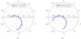
Input impedance simulated for inductor of 6.6 nH (a) Results before scaling the antenna radius (a = 17.64 mm); (b) Final design (a = 19.28 mm).
IV. EXPERIMENTAL VALIDATION
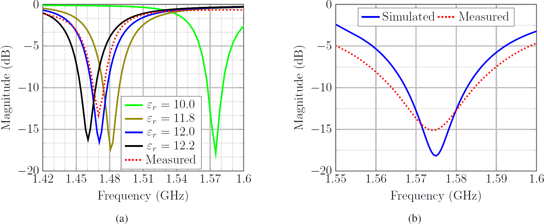
After the computational design, a prototype of the proposed antenna was built. The comparison between the simulated and measured reflection coefficients is shown in Fig. 7(a). A large discrepancy between computed and measured results can be observed. A parametric simulation has been carriedout by varying the dielectric constant of the laminate CER-10 whilst keeping the antenna dimensions unchanged. As demonstrated in Fig. 7(a), good agreement between simulated and measured results has been obtained for ɛr = 12. This approach allows calibrating the electromagnetic model to the real dielectric constant, which can deviate from the nominal value due to several reasons, such as moisture absorption or other environmental reasons.
Comparison between simulated and measured reflection coefficient: (a) Different values for ɛr and L = 6.6 nH.; (b) Final prototype with ɛr = 12 and L = 5.2 nH.
To shift the antenna resonance frequency, the design approach described in Section III has been calibrated by considering now ɛr = 12. The new antenna radius was optimized to a = 18.22 mm.The coaxial probe was kept at (ρ0, ϕ0) = (7 mm, 45◦) and the series inductor has been changed to L = 5.2 nH. A second prototype has been fabricated and the comparison between the simulated and measured magnitude of the reflection coefficient is presented in Fig. 7(b), where very good impedance matching in the desired frequency can be observed now. The comparison between the simulated and measured radiation patterns at the design frequency is shown in Fig. 8 for the xz-plane (Fig. 8(a)) and the yz-plane (Fig. 8(b)), whereby very good agreement has been obtained. A photo of the final prototype is shown in Fig. 9. Table I highlights the novelty of this work in comparison to previously published papers related to the design of DRAs found in the open literature.

Comparison between simulated and measured radiation patterns at 1.575 GHz: (a) xz-plane (E-plane); (b) yz-plane (H-plane).

V. CONCLUSION
In this letter, the design of a top-loaded quarter-cylinder dielectric resonator antenna was presented. The main contributions of the proposed design are the synthesis of the E-wall with cylindrical viasand the use of a series inductor for impedance matching on top of the structure. Several analyses were carried out and demonstrated the versatility of the proposed design. By considering ɛr = 12 for the used microwave laminate during the antenna design, good agreement between simulations and measurements in terms of radiation pattern and reflection coefficient has been obtained. The simulated radiation efficiency for this last prototype considering ɛr = 12 was equivalent to 72.89% with a maximum gainof 4.5 dBi. Finally, the proposed design yields higher compactness, which is an important feature if volume and weight are critical, such as the case of space applications.
ACKNOWLEDGMENTS
This work has been partially supported by Conselho Nacional de Pesquisa e Desenvolvimento Tecnológico (CNPq) under grants 407245/2022-7, 305654/2022-5 and 406517/2022-3 (INCT-Signals).
REFERENCES
-
[1] S. Gupta, P. Kshirsagar, and B. Mukherjee, “A low-profile multilayer cylindrical segment fractal dielectric resonator antenna: Usage for wideband applications,” IEEE Antennas and Propagation Magazine, vol. 61, no. 4, pp. 55-63, 2019, DOI: 10.1109/MAP.2019.2920424.
» https://doi.org/10.1109/MAP.2019.2920424. -
[2] P. Ranjan and R. K. Gangwar, “Probe feed half split cylindrical dielectric resonator antenna for wideband application,” AEU - International Journal of Electronics and Communications, vol. 69, no. 11, pp. 1709-1714, 2015, DOI: 10.1016/j.aeue.2015.08.006.
» https://doi.org/10.1016/j.aeue.2015.08.006. -
[3] M. Belazzoug, I. Messaoudene, S. Aidel, T. Denidni, and A. Kishk, “Quarter cylindrical dielectric resonator antenna with circular polarisation for wideband MIMO systems,” Electronics Letters, vol. 56, no. 4, pp. 174-176, 2020, DOI: 10.1049/el.2019.3138.
» https://doi.org/10.1049/el.2019.3138. -
[4] H. N. Chen, J.-M. Song, and J.-D. Park, “A compact circularly polarized MIMO dielectric resonator antenna over electromagnetic band-gap surface for 5G applications,” IEEE Access, vol. 7, pp. 140 889-140 898, 2019, DOI: 10.1109/ACCESS.2019.2943880.
» https://doi.org/10.1109/ACCESS.2019.2943880. -
[5] J. W. O. Bezerra, D. G. Sousa, C. C. M. Junqueira, M. A. S. Silva, G. C. Barroso, and A. S. B. Sombra, “Circularly polarized quarter-cylinder-shaped dielectric resonator antenna using a single probe feed,” Microwave and Optical Technology Letters, vol. 57, no. 3, pp. 722-726, 2015, DOI: 10.1002/mop.28930.
» https://doi.org/10.1002/mop.28930. -
[6] D. Surender, M. A. Halimi, T. Khan, F. A. Talukdar, and Y. M. M. Antar, “A 90° twisted quarter-sectored compactand circularly polarized DR-rectenna for RF energy harvesting applications,” IEEE Antennas and Wireless Propagation Letters, vol. 21, no. 6, pp. 1139-1143, 2022, DOI: 10.1109/LAWP.2022.3159482.
» https://doi.org/10.1109/LAWP.2022.3159482. -
[7] S. Caizzone, “Miniaturized E5a/E1 antenna array for robust GNSS navigation,” IEEE Antennas and Wireless Propagation Letters, vol. 16, pp. 485-488, 2017, DOI: 10.1109/LAWP.2016.2585353.
» https://doi.org/10.1109/LAWP.2016.2585353. -
[8] L. Huitema, M. Koubeissi, C. Decroze, and T. Monediere, “Ultrawideband dielectric resonator antenna for DVBH and GSM applications,” IEEE Antennas and Wireless Propagation Letters, vol. 8, pp. 1021-1027, 2009, DOI: 10.1109/LAWP.2009.2031332.
» https://doi.org/10.1109/LAWP.2009.2031332. -
[9] M. Tam and R. Murch, “Compact circular sector and annular sector dielectric resonator antennas,” IEEE Transactions on Antennas and Propagation, vol. 47, no. 5, pp. 837-842, 1999, DOI: 10.1109/8.774138.
» https://doi.org/10.1109/8.774138. - [10] M. Cooper, A. Petosa, A. Ittipiboon, and J. S. Wight, “Investigation of dielectric resonator antennas for L-band communications,” in 1996 Symposium on Antenna Technology and Applied Electromagnetics, 1996, Montreal, QC, Canada.
-
[11] M. Tam and R. Murch, “Half volume dielectric resonator antenna designs,” Electronics Letters, vol. 33, pp. 1914- 1916(2), 1997, DOI: 10.1049/el:19971334.
» https://doi.org/10.1049/el:19971334. -
[12] --, “Circularly polarized circular sector dielectric resonator antenna,” IEEE Transactions on Antennas and Propagation, vol. 48, no. 1, pp. 126-128, 2000, DOI:10.1109/8.827396.
» https://doi.org/10.1109/8.827396. -
[13] A. A. Kishk and W. Huang, “Size-reduction method for dielectric-resonator antennas,” IEEE Antennas and Propagation Magazine, vol. 53, no. 2, pp. 26-38, 2011, DOI: 10.1109/MAP.2011.5949322.
» https://doi.org/10.1109/MAP.2011.5949322. -
[14] R. Chowdhury and R. K. Chaudhary, “Investigation on different forms of circular sectored-dielectric resonator antenna for improvement in circular polarization performance,” IEEE Transactions on Antennas and Propagation, vol. 66, no. 10, pp. 5596-5601, 2018, DOI: 10.1109/TAP.2018.2854418.
» https://doi.org/10.1109/TAP.2018.2854418. -
[15] S.-K. Zhao, N.-W. Liu, Q. Chen, G. Fu, and X.-P. Chen, “A low-profile dielectric resonator antenna with compactsize and wide bandwidth by using metasurface,” IEEE Access, vol. 9, pp. 29 819-29 826, 2021, DOI: 10.1109/AC-CESS.2021.3058352.
» https://doi.org/10.1109/AC-CESS.2021.3058352 -
[16] R. Mongia, “Reduced size metallized dielectric resonator antennas,” in IEEE Antennas and Propagation Society International Symposium 1997. Digest, vol. 4, pp. 2202-2205, 1997, DOI: 10.1109/APS.1997.625406.
» https://doi.org/10.1109/APS.1997.625406. -
[17] J. M. Vieira and M. V. T. Heckler, “Analysis of via-fed cylindrical dielectric resonator antennas,” Microwave and Optical Technology Letters, vol. 62, no. 12, pp. 3905-3910, 2020, DOI: 10.1002/mop.32513.
» https://doi.org/10.1002/mop.32513. -
[18] Z. Li, C. Wu, and J. Litva, “Adjustable frequency dielectric resonator antenna,” Electronics Letters, vol. 32, pp. 606- 607(1), 1996, DOI: 10.1049/el:19960462.
» https://doi.org/10.1049/el:19960462. -
[19] Z.-N. Chen, K.-W. Leung, K.-M. Luk, and E. K.-N. Yung, “Effect of parasitic disk on a coaxial probe-fed dielectric resonator antenna,” Microwave and Optical Technology Letters, vol. 15, no. 3, pp. 166-168, 1997, DOI: 10.1002/(sici)1098-2760(19970620)15:3<166::aid-mop12>3.0.co;2-5.
» https://doi.org/10.1002/(sici)1098-2760(19970620)15:3<166::aid-mop12>3.0.co;2-5. -
[20] M. V. T. Heckler and A. Dreher, “Analysis of conformal microstrip antennas with the discrete mode matching method,” IEEE Transactions on Antennas and Propagation, vol. 59, no. 3, pp. 784-792, 2011, DOI: 10.1109/TAP.2010.2103014.
» https://doi.org/10.1109/TAP.2010.2103014.