Beamforming Direction of Arrival (DoA) Based in a Software-Defined Radio
Abstract
This paper presents the development and experimental validation of a low-cost Direction of Arrival (DoA) estimation system using Software-Defined Radio (SDR) technology. The system employs an NI USRP B-210 with two printed log-periodic dipole antennas in a coherent configuration, implementing beamforming algorithms through GNU Radio software. Experimental validation was conducted in different environments at 3 GHz across a ±90◦ range. The system maintains accurate DoA estimates with interference levels up to 8 dB below the signal of interest. Performance limitations include front-back ambiguity inherent to two-element arrays and sensitivity to multipath effects. This work demonstrates the feasibility of replacing expensive commercial DoA systems with affordable SDR-based alternatives, with advantages such as easy deployment and reconfigurability.
Index Terms
Direction of Arrival; Radars; Signal Processing; Softwaredefined Radio.
I. INTRODUCTION
Direction of Arrival (DoA) estimation is a fundamental technique in signal processing and electromagnetic systems that determines the spatial location of radio frequency sources. Traditional DoA systems have relied on expensive specialized hardware such as dedicated spectrum analyzers and highprecision receivers, often limiting their accessibility.
This capability has found extensive applications across diverse fields including radar systems, wireless communications, electromagnetic compatibility (EMC) testing, and electronic warfare scenarios [1], [2]. Classical DoA estimation methods include subspace-based techniques such as MUSIC (Multiple Signal
Classification) [2] and ESPRIT (Estimation of Signal Parameters via Rotational Invariance Techniques) [3], [4], as well as beamforming approaches including Capon’s method [5] and minimum variance distortionless response (MVDR) techniques [1], [6].
The theoretical foundations of array signal processing have been extensively developed over the past decades [1], [6], [14]. High-resolution techniques such as MUSIC and ESPRIT offer superior angular resolution compared to conventional beamforming, particularly when dealing with closely spaced sources [2], [3], [15]. However, these methods require accurate knowledge of the number of sources [16] and are sensitive to model errors and finite sample effects [15], [17]. For coherent signal sources, spatial smoothing techniques have been developed to maintain performance [17]. Though showing theoretical advantages, these advanced algorithms often require complex calibration procedures and significant computational resources, making conventional beamforming an attractive alternative for real-time applications where robustness and computational efficiency are prioritized over resolution.
In terms of hardware platforms, the emergence of Software-Defined Radio technology has revolutionized the field by providing cost-effective alternatives to conventional RF instrumentation [7], [8]. As SDR replaces traditional hardware components such as modulators, mixers, filters by on-the-fly software modifications, they allow a programmed and flexible operation. They offer unprecedented flexibility by implementing signal processing functions in software rather than fixed hardware, enabling researchers and engineers to develop customized solutions for specific applications.
Regarding recent advances in open-source software tools to acquire and process the SDR samples, one solution is the GNU Radio suite. Being open source, it helps widen the access to sophisticated signal processing capabilities [9], [10]. These platforms enable the implementation of complex algorithms such as beamforming and spatial filtering using standard computing hardware, dramatically reducing the barrier to entry for advanced RF applications [11]. The combination of low-cost SDR hardware with powerful open-source software creates opportunities for innovative solutions in areas previously dominated by expensive commercial instruments. Besides, the open source nature in general has a wide collaborative network, in terms of libraries, examples and tutorials, available online.
However, the implementation of DoA systems using SDR platforms presents unique challenges that must be carefully addressed. Phase coherence between multiple receiver channels, antenna calibration, front-back ambiguity resolution, and interference mitigation are critical considerations that directly impact system performance [12], [13]. Understanding these limitations and developing appropriate compensation strategies is essential for achieving reliable DoA estimates in practical environments.
In the open literature there are similar reported works, for instance the implementation of an 536MHz ESPRIT-based DoA method using 16 dipole antennas, switched in time-domain to serve as inputs to a 4-ports Lyrtech SDR [18]. Also based in SDRs, a DoA estimation system based in a single antenna operates as a virtual multiantenna array, as an alternative to large antenna arrays. Experiments were carried out in an indoor environment, at the center frequency of 1 GHz [19]. Using a Lyrtech digital to analog converter, 2.4 GHz RF transceivers and a single reconfigurable leaky wave antenna, a DoA estimator based in the MUSIC algorithm was tested, which processed the baseband samples received in a PC [20]. Using a low-cost NI USRP B210 a MUSIC DoA technique was implemented with two omnidirectional antennas, at the frequency of 2.44 GHz, with emphasis on the phase errors caused by the hardware and its mitigation [21].
This work presents the development and characterization of a low-cost DoA system based on offthe-shelf SDR hardware. It demonstrates the feasibility of replacing traditional spectrum analyzers and specialized receivers with affordable, versatile software-defined alternatives while maintaining acceptable measurement accuracy. Through systematic evaluation in controlled environments, including anechoic chamber testing and jamming scenarios, this research establishes the practical boundaries and limitations of SDR-based DoA systems.
The primary contributions of this work include: (1) a complete hardware and software implementation using commercially available components, (2) quantitative performance characterization under various operating conditions, (3) analysis of interference tolerance and robustness, and (4) identification of key trade-offs inherent in two-element array configurations. These results provide valuable insights for researchers and practitioners considering SDR-based approaches for DoA applications in experiments with radar and antennas.
II. HARDWARE
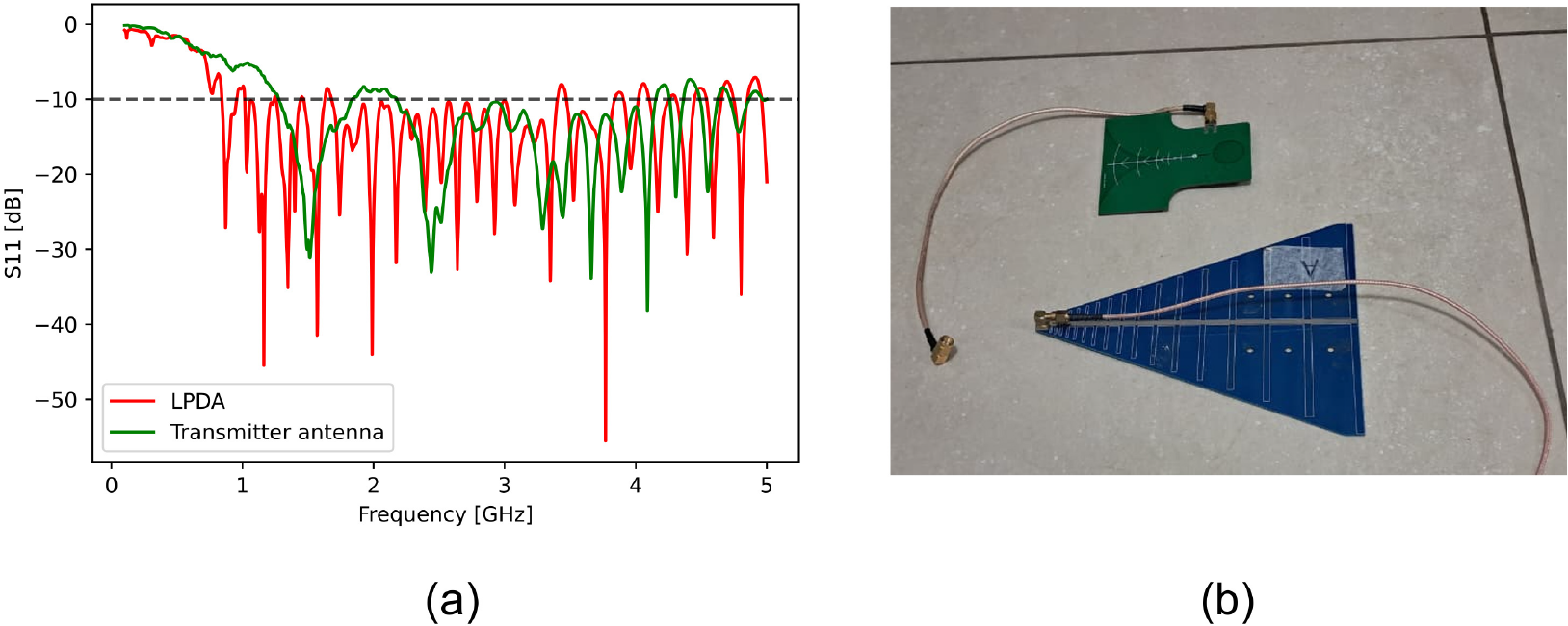
The system is based on the NI USRP B-210 software defined radio, which has 4 ports, also known as channels, configurable as 2 transmitters and 2 receivers, MIMO-capable, sharing the same locked local oscillator. It can operate from 70 MHz to 6000 MHz, with a maximum instantaneous bandwidth of 56 MHz and an ADC with 12 bits of resolution. The instantaneous bandwidth is divided by the number of ports, since two are used, the maximum sampling rate (other name for the bandwidth) is halved, 28 MHz. Since the DoA operation extracts the information encoded in the relative phase received by two channels, the instrument needs to have both ports coherent, with the same stable phase reference. Two printed log-periodic antennas (LPDA) were connected to receiver ports in the SDR. The cables have same length, to avoid phase errors which will eventually translate as wrong measured angles. A broadband planar antenna was used connected to a transmitter, whose results in terms of S11 are shown in Fig. 1 for both antennas. They were measured with a vector network analyzer Rohde & Schwarz ZNB26. The transmitter was a board based on the ADF4351, which covers the range from 35 MHz to 4440 MHz, maximum output power of 5 dBm, divided in two differential ports.
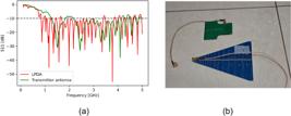
Measured S11 parameters (a) for the receiving (LPDA) and transmitter units, shown in detail (b).
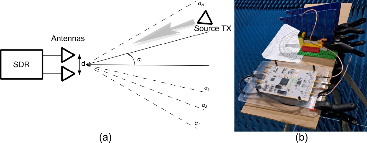
Fig. 2 shows the integrated system, in both block diagram as well as the actual implementation. The antennas are fixed at a distance d and have the angular reference found by means of a printed protractor. The cables and connectors are matched, to minimize phase errors.
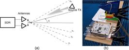
(a) Block diagram of the system and (b) actual prototype. The distance d is set to half-wavelength.
A. Limitations of a 2-Element Array
The use of two antennas is constrained by the particular SDR available ports. In spite of its four ports, only two are allowed to be simultaneously operate as receiver. The generic array factor AF for a two-element array can be written as:
where θ is the angle, with 90◦ representing the broadside direction, which simplifies the analysis without any loss of generality. The phase factor Ψ encompasses both the distance and the excitation factors:
where k is the wavenumber, d the distance between two elements and α the electrical phase difference. AF is then for separation of half-wavelength:
It is important to note that the theoretical formulation of the array factor assumes isotropic radiating elements and serves primarily as a conceptual framework. In the implemented system, the Direction of Arrival estimation is performed directly on the received signals through delay-and-sum beamforming. As such, the resulting spatial response inherently includes both the array factor and the individual antenna element patterns. Therefore, the estimated DoA corresponds to the maximum of the combined array response, without requiring explicit separation between array factor and element radiation characteristics. The use of directional LPDA antennas, with a measured front-to-back ratio of 11.5 dB, contributes to partially mitigating front-back ambiguity and influences the overall angular sensitivity of the system.
The problem that arises when only two elements are used is the so-called front-back ambiguity. It stems from the fundamental cosine periodic property:
Therefore:
It means, a 2-element array will have its array factor pattern also periodic in the spatial domain, thereby causing an ambiguity. Usual methods to address this limitations are:
-
• Adding a third antenna element to break the symmetry (requires RF switching with the available SDR);
-
• employing directional antenna elements with amplitude tapering;
-
• leveraging prior knowledge of source locations, thereby limiting the sweep angles;
-
• using multi-frequency measurements.
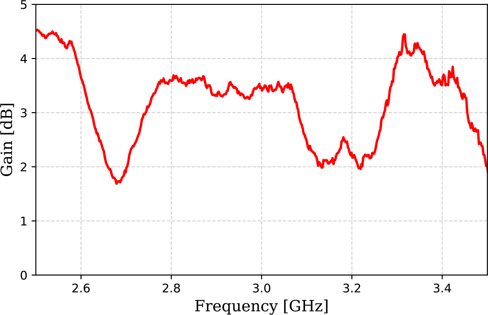
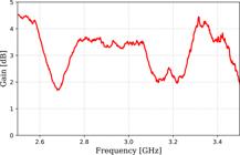
In terms of gains, both TX and RX antennas had a gain of approximately 3.4 dB, measured in 3 GHz. The LPDA in particular has a measured front-to-back relation of 11.5 dB, partially suppressing back-lobe ambiguities. Fig. 3 shows the measurement of the realized gain of an individual LPDA element, taken at maximum (endfire) position.
III. SOFTWARE
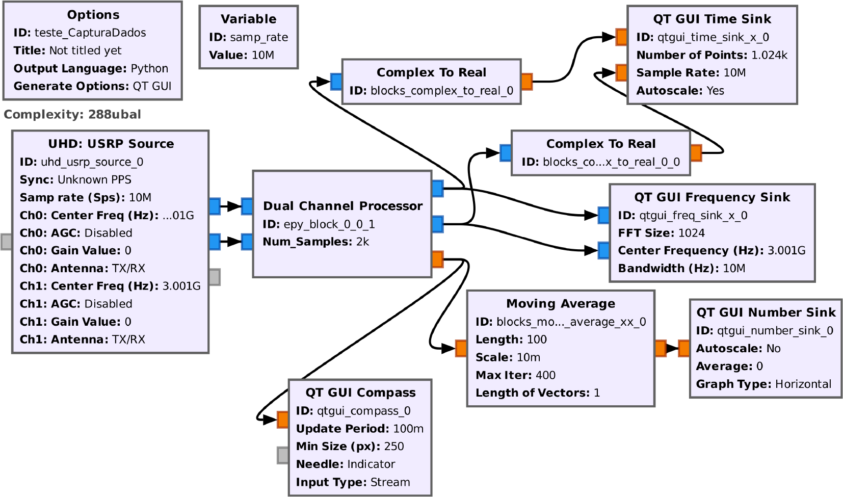
GNU Radio was chosen to acquire the RF samples from the two SDR channels and process it, eventually displaying the estimated DOA angles. It is an open-source tool, and its GNU Radio Companion offers an interactive visual block-oriented interface, where most mathematical and hardware-oriented functions are written in C whereas Python is used as wrapper. Fig. 4 shows the GNU Radio Companion flowgraph.
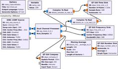
The Dual Channel Processor block contains a Python code that actually implements the Direction of Arrival using the delay-and-sum algorithm, taken as inputs the samples of both SDR outputs. The choice of the delay-and-sum beamforming algorithm is motivated by its robustness and suitability for practical SDR-based implementations. Although high-resolution techniques such as MUSIC and ESPRIT provide superior angular discrimination, their performance relies on accurate knowledge of the number of sources, precise array calibration, and favorable signal conditions, including high signalto-noise ratios and uncorrelated sources. In contrast, delay-and-sum beamforming operates directly on the received signals without requiring prior model assumptions or covariance matrix decomposition, making it inherently more tolerant to model mismatches, phase uncertainties, and finite sample effects.
From an implementation perspective, delay-and-sum is particularly well suited for real-time processing on general-purpose hardware, as its computational complexity scales linearly with the number of scanned angles and samples, avoiding the eigenvalue decomposition required by subspace-based methods. This is relevant in SDR platforms such as the USRP B210 combined with GNU Radio, where processing resources and latency must be carefully managed.
Furthermore, considering the two-element array configuration adopted in this work, the theoretical advantages of subspace methods are limited, since their resolution gains become significant only for larger arrays. Under such constraints, delay-and-sum provides a more consistent and reliable estimation framework. Therefore, the selected approach represents a balanced trade-off between accuracy, computational efficiency, and implementation complexity, aligning with the objective of developing a low-cost, easily deployable DoA estimation system.
The delay-and-sum block continuously collects radio samples from both antennas, beamforming the space to scan different directions. The system creates a "virtual beam" that can be electronically steered in different directions by applying phase shifts to the antenna signals, with a software loop inside the block. According to Fig. 2, weights are applied to the received individuals samples so that the main beam is steered towards the angle of αi. When the beam points toward the actual signal source, the combined power is maximized. The result is output as an angle in degrees. The core math involves calculating how much delay (phase shift) each antenna should have based on the geometric arrangement and the test angle. This simulates the natural time-of-arrival differences. By testing 180 different angles and measuring the resulting signal power for each, the system finds the direction that produces the signal with the largest amplitude, the most likely source direction. The system runs continuously, updating the direction estimate every time it collects a full buffer of samples (1024 in this case), while passing the original signals through unchanged for further processing. The pseudo-code is shown in Algorithm 1. The actual implementation is written in Python, whose necessary functions are called from the numpy library.
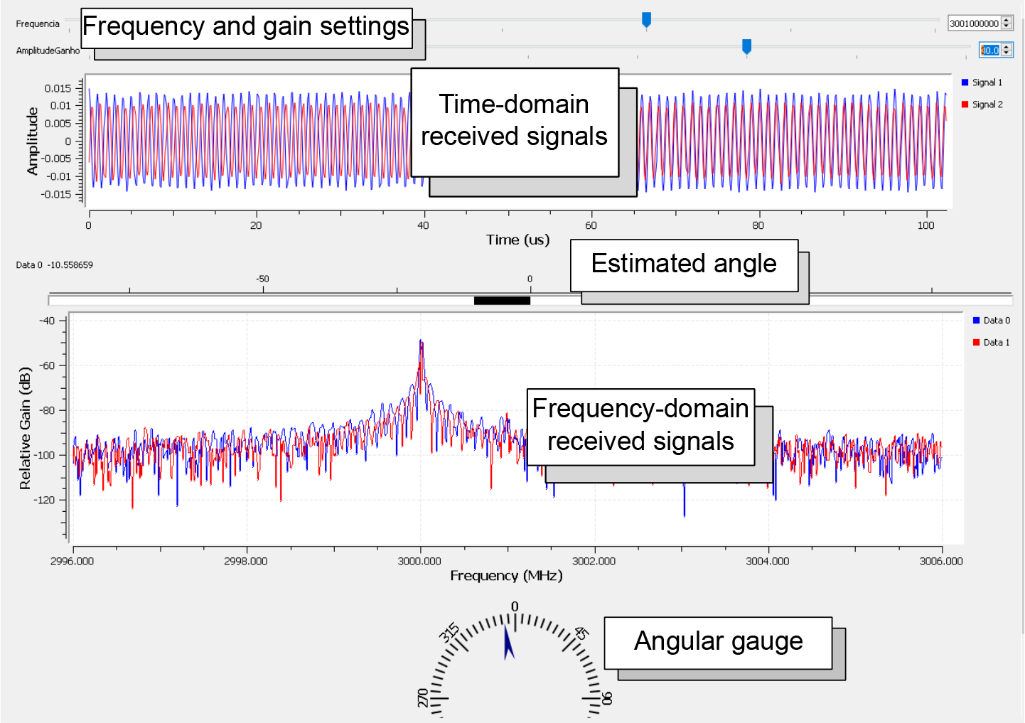
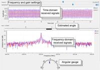
The code delivers a sequence of angles, which are later smoothed out by a moving average filter of 100 elements, and also shown in a compass-like gauge, to better visualize the source position estimate. Fig. 5 shows the user interface during operation, where the amplitude and frequency can be adjusted on-the-fly, and receiving signals in both time and frequency domains are visualized. The estimated angle is shown in both numerical field element as well as an angular gauge. A final note is the use of small offset between the transmitter and SDR central frequency, as to avoid zero-IF leakage, which in view of the small received amplitudes might be a problem. Here, 1 MHz was chosen. As long as the offset is within the sampling rate window (here 10 MHz) this offset does not impose any problem.
The beamforming algorithm implements a sliding window approach with 1024-sample buffers, corresponding to approximately 102.4 µs of data at 10 MSPS sampling rate. Angular resolution is determined by the number of tested angles (180 in this implementation, providing 1◦ resolution) and the array aperture. The computational complexity is O(N·M) where N is the number of samples and M is the number of test angles.
Algorithm 1 The DoA Estimation algorithm.
1: DoA_Estimation(antenna_samples): {Two-channel antenna samples input, returns direction angle in degrees}
2: num_samples ← 1024
3: spacing ← 0.5
4: Initialize buffer
5: samples_collected ← 0
6: while processing data blocks do
7: if samples_collected < num_samples then
8: copy samples to buffer
9: samples_collected ← samples_collected +1
10: end if
11: if buffer is full then
12: best_direction ← estimate_direction(buffer)
13: output direction estimate
14: end if 15: end while
16:
17: estimate_direction(samples):
18: max_power ← 0
19: best_angle ← 0
20: for angle = -90◦ to +90◦ do
21: calculate beamforming weights for angle
22: power ← mean(|combined_signal|2)
23: if power > max_power then
24: max_power ← power
25: best_angle ← angle
26: end if
27: end for
28: return best_angle
IV. MEASUREMENTS
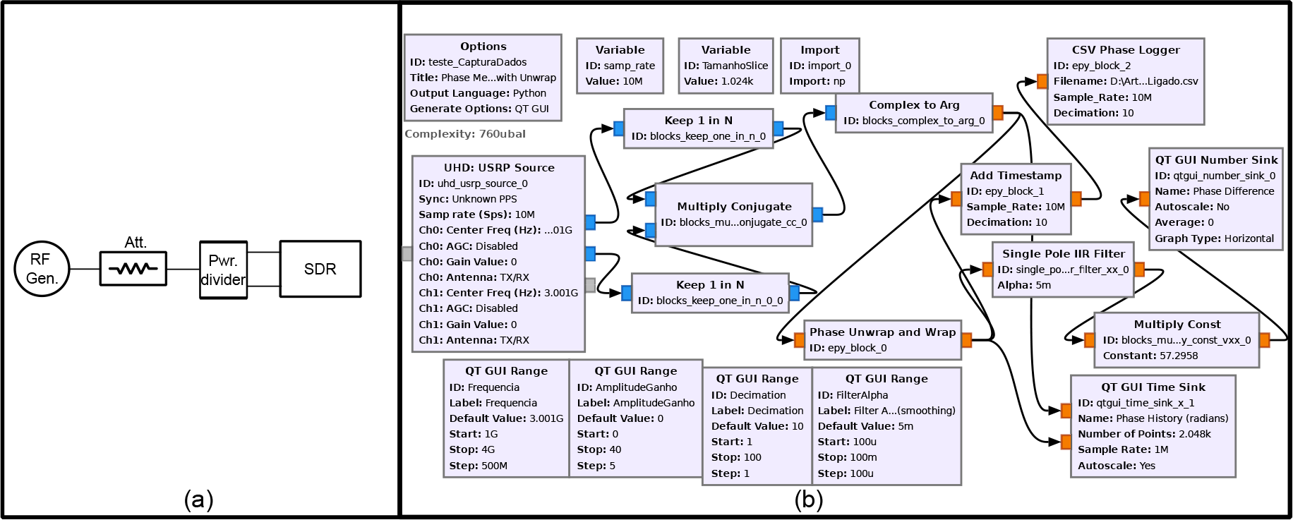
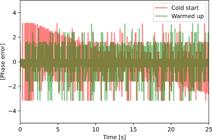
Prior to the actual measurement an evaluation of the error phase inherent to the SDR is performed. To address that, both ports of the SDR were subjected to the same RF signal, as Fig.6 shows. Two cables with the same length connect the power divider output to the respective input ports. The SDR inputs are also protected by a 30-dB attenuator, located right after the RF generator. The GNU Radio companion flowgraph actually performs a conjugate multiplication between both the SDR inputs, to extract the phase. The results are also saved in a comma-separated value (CSV) file, where to each phase the respective time stamp is associated. The result undergoes than a low-pass filtering by a single-pole infinite impulse filter (IIR), prior to be displayed to the user interface.
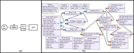
(a) Hardware block diagram and (b) GNU-Radio companion program to measure the phase imbalance measurement.
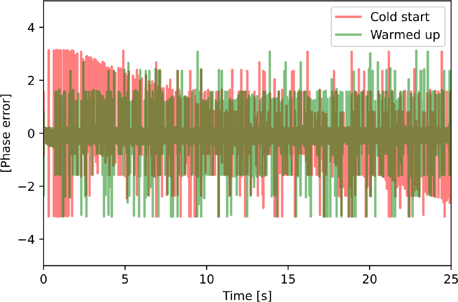
Results are presented in Fig. 7. Two situations were tested, just after the SDR and generator were turned on and after their temperature was stabilized (approximately 20 minutes). It can be seen that though the phase error is close to zero in the average, large spikes occur (between ±2.5◦), which are likely caused by the data transmission between the computer and the SDR. It is also visible that at the cold start the spikes are more pronounced, so it points out to an actual hardware temperaturestabilization problem. Nevertheless, the phase imbalance error in the form of spikes can be minimized by means of averaging in the actual DoA program shown in Fig. 4, and it is still smaller than the manually measured angle.
A. Standard Operation
The system was measured in an anechoic chamber (dimensions 4 m × 6 m × 3.5 m), to avoid interference with other emissions and dampen reflections in obstructions and walls. The transmitter output power was set to 5 dBm, frequency of 3 GHz, and positioned at about 5 meters from the receiving array, at different angles. The 3 GHz operating frequency was selected to enable a compact antenna array (λ/2 spacing = 5 cm) and because it did not have any existing emissions. The endfire direction, where the gain is maximum at uniform excitation, was defined as 0◦, for simplicity. The real angles were manually measured with a laser pointer with a protractor, which had an imprecision of about 2◦.
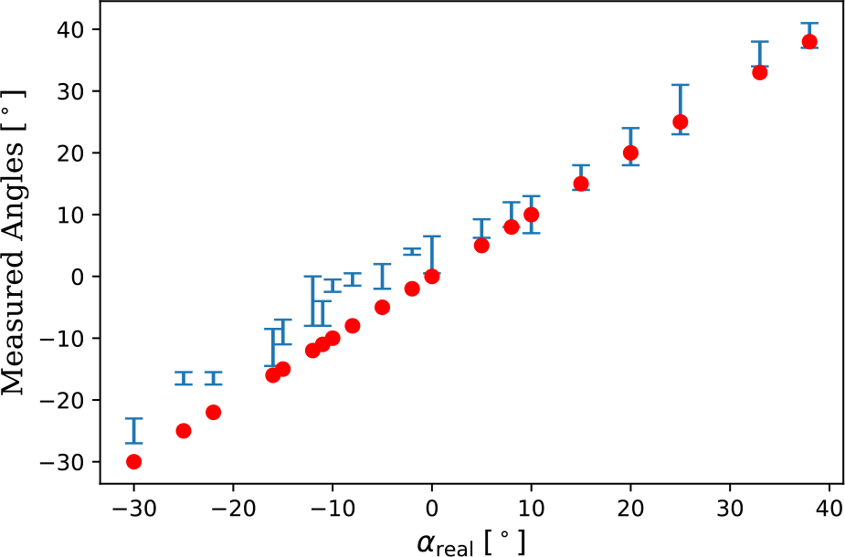
The parameters are described as the real angle αreal and the measurements are within the limts αmin and αmax. Fig. 8 shows the results, with a bar around each measured angle representing the maximum and minimum value. Angular errors are unevenly spread across the -90◦ to 90◦ total range, found to be larger close to the negative angles. This was likely caused by misalignment and unsymmetry in the mechanical assembly that supports the antenna array. The maximum error was observed at 30◦, 8◦ from the minimum DoA measurement.
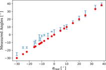
Results of the measured angle using the proposed system. The horizontal bars indicate αmin and αmax, and the red circles the actual position αreal.
B. Jammed Operation
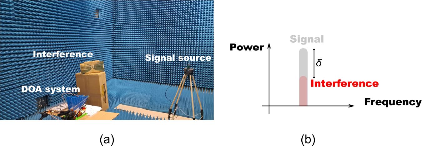
In actual battlefield or real-world scenarios a DoA system has to withstand interferences, both unintentional and intentional, the latter the case of jamming. In order to address this case, an experiment was carried out where the same transmitter and SDR processor were used, with another omnidirectional dipole antenna operating with an adjustable output source serving as a jammer source, as shown in Fig. 9. Frequency was set to 3 GHz, and both interference and signal source was approximately 3 meters from the DoA system. The goal is finding out the maximum difference between the jamming and signal power which still provides an adequate estimate in the GNU Radio application. The difference in power, expressed in dB, at the receiving site, between the signal and the interference, is defined as:
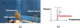
(a) Elements placed to address the effect of an interference source on the DoA estimate, defined according to (b).
where Psig and Pint are respectively the signal and intereference power levels.
The interference source was positioned at 26◦ whereas the signal was at -5◦. Then, the procedure to determine the maximum level of admitted interference was first adjust the amplitude level of both signals to generate the same received power, in the SDR. From that point, the interference power was decreased until a stable DoA αest reading was measured. The results are presented in Table I.
It was found that the system withstood interference power levels up to 8 dB below the signal, showing the same estimate angle. For differences smaller than 8 dB the DoA reading showed deviations, gradually shifting αest towards the interference position.
C. Environmental Robustness Testing
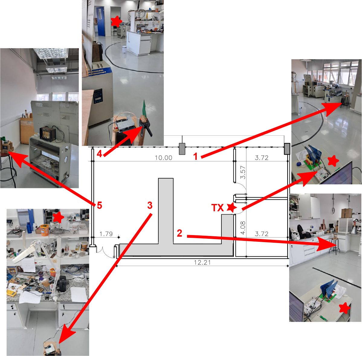
A test in an indoor environment with clutter and reflections was carried out in a laboratory with dimensions 14 m × 7.7 m, in different points as shown in Fig. 10. The goal was to evaluate the overall performance under a more realist wireless channel. The SDR had its gain set to 20 dB, and the RF source was with a 5 dBm output, using the same antennas and the frequency of 3 GHz.
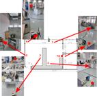
Indoor environment to test the DoA system under clutter. The star symbol lies on the SDR and antennas position.
Five different positions were tested, in particular, the site number 5 had one 1m × 1 m metallic plate partially interrupting the line of sight direction between the source and the SDR antennas. The results are summarized in Table II. The measurements are within the limts αmin and αmax, whose mean is expressed as α. The error err is defined as:
The mean and standard deviation were computed from the minimum and maximum estimated angles, assuming a symmetric distribution around their midpoint.
The results showed that the cluttered ambient indeed generated a larger degree of imprecision, particularly seen when the line of sight is partially obstructed as in the position 5. When the source was at point number 4 a large degree of error was observed, likely given the reflections and systematic errors. Table III summarizes the maximum error observed for the two different tested environments, the cluttered indoor laboratory and the anechoic chamber.
V. CONCLUSIONS
This work demonstrates a practical low-cost Direction of Arrival estimation system using commercial SDR hardware (NI USRP B-210) and open-source processing tools (GNU Radio). The system achieves angular resolution of approximately 2-10◦ across ±90◦ in controlled conditions, representing a viable alternative to costly commercial DoA systems.
Key findings include:
-
1. Phase coherence: The USRP B-210 exhibits ±2.5◦ phase errors that stabilize after 20-minute warm-up, manageable through temporal averaging.
-
2. Interference tolerance: The conventional beamforming approach maintains accuracy with interference up to 8 dB below the signal of interest, beyond which estimates degrade gracefully toward the interferer location.
-
3. Environmental sensitivity: Performance degrades in cluttered environments with multipath propagation, particularly under partial line-of-sight obstruction.
-
4. From Table III, the cluttered scenario generated smaller errors in contrast to the anechoic chamber,which signals a larger sensitivity to mechanical alignements in comparison to electromagnetic reflections. Inside the chamber adjustements and available physical space was limited therefore it impacted on the correct angular measurements.
The two-element array configuration presents fundamental limitations, primarily front-back ambiguity only partially mitigated by directional antennas. The ±2◦ manual reference measurement uncertainty, carried out with a laser pointer and a protactor, significantly limits accuracy assessment. The software implementation enables a quick and easy modification of its core parameters, such as central frequency, level of internal RF gain, etc, as well as the beamforming characteristics, like buffer size, amplitude of sweep angles, spatial resolution etc.
A clearer comparison with prior works highlights the distinctive contributions of this study. In contrast to high-resolution subspace-based techniques such as MUSIC and ESPRIT [2] - [4], which offer superior angular resolution but require accurate model order estimation and are sensitive to calibration errors and finite sample effects [15] - [17], the present work adopts a conventional delayand-sum beamforming approach. While this choice inherently limits resolution, it significantly reduces computational complexity and improves robustness, making it more suitable for real-time and resourceconstrained SDR implementations.
When compared to recent SDR-based DoA systems, important differences emerge. The system in [18] employs a larger effective array through antenna switching and multiple RF channels, increasing hardware complexity and synchronization requirements. Similarly, the virtual array approach in [19] and the reconfigurable antenna strategy in [20] reduce the need for multiple RF chains but introduce additional challenges such as motion, switching artifacts, or antenna reconfiguration constraints. The work in [21], although also based on a USRP B210 platform and MUSIC processing, focuses primarily on phase error mitigation rather than full system-level validation under realistic operating conditions.
In contrast, the present study emphasizes a minimalist and fully coherent two-channel architecture, requiring no switching, virtual array synthesis, or complex calibration procedures. Its main contribution lies in the comprehensive experimental validation, including controlled anechoic measurements, interference (jamming) tolerance characterization, and operation in cluttered indoor environments. This combination of low hardware complexity, open-source implementation, and systematic performance assessment distinguishes the work as a practical and reproducible solution for low-cost DoA estimation. While the two-element configuration imposes known limitations such as front-back ambiguity, the results demonstrate that acceptable accuracy can still be achieved for many practical applications where cost, simplicity, and deployability are primary constraints.
DATA AVAILABILITY STATEMENT
The data that support the findings of this study are available upon request via email.
REFERENCES
- [1] H. L. Van Trees, Optimum Array Processing: Part IV of Detection, Estimation, and Modulation Theory WileyInterscience, New York, 2002.
-
[2] R. Schmidt, “Multiple emitter location and signal parameter estimation,” IEEE Transactions on Antennas and Propagation, vol. 34, no. 3, pp. 276-280, 1986, DOI: 10.1109/TAP.1986.1143830
» https://doi.org/10.1109/TAP.1986.1143830 -
[3] R. Roy, T. Kailath, “ESPRIT-estimation of signal parameters via rotational invariance techniques,” IEEE Transactions on Acoustics, Speech, and Signal Processing, vol. 37, pp. 984-995, 1989, DOI: 10.1109/29.32276
» https://doi.org/10.1109/29.32276 - [4] A. Paulraj, R. Roy, T. Kailath, “Estimation of signal parameters via rotational invariance techniques - ESPRIT”, Proceedings of the 19th Asilomar Conference on Circuits, Systems, and Computers, pp. 83-89, 1985.
-
[5] J. Capon, “High-resolution frequency-wavenumber spectrum analysis,” Proceedings of the IEEE, vol. 57, pp. 1408- 1418, 1969, DOI: 10.1109/PROC.1969.7278
» https://doi.org/10.1109/PROC.1969.7278 - [6] S. Haykin, Array Signal Processing Prentice Hall, Englewood Cliffs, 1985.
- [7] T. F.Collins, R. Getz, D. Pu, A. M. Wyglinski, Software-Defined Radio for Engineers Artech House, Norwood, 2018.
- [8] C. Laufer, The Hobbyist’s Guide to the RTL-SDR: Really Cheap Software Defined Radio CreateSpace, Scotts Valley, 2015.
- [9] D. S. W. Atkinson, K. W. Barlee, R. W. Stewart. Software Defined Radio Using MATLAB & Simulink and the RTL-SDR University of Strathclyde, Glasgow, 2015.
-
[10] R. W. Stewart, L. Crockett, D. Atkinson, K. Barlee, D. Crawford, I. Chalmers, “A low-cost desktop software defined radio design environment using MATLAB, Simulink, and the RTL-SDR,” IEEE Communications Magazine, vol. 53, pp. 64-71, 2015, DOI: 10.1109/MCOM.2015.7263347
» https://doi.org/10.1109/MCOM.2015.7263347 -
[11] M. Chino, H. Miyashiro, J. A. Luis, “Implementation of SNR estimation algorithms, using LabVIEW Communications and GNU Radio Companion,” 2018 IEEE XXV International Conference on Electronics, Electrical Engineering and Computing (INTERCON), pp. 1--4, 2018, DOI: 10.1109/INTERCON.2018.8526396
» https://doi.org/10.1109/INTERCON.2018.8526396 -
[12] B. D. Van Veen, K. M. Buckley, “Beamforming: a versatile approach to spatial filtering,” IEEE ASSP Magazine, vol. 5, pp. 4-24, 1988, DOI: 10.1109/53.665
» https://doi.org/10.1109/53.665 -
[13] A. J. Paulraj, R. Roy, T. Kailath, “A subspace rotation approach to signal parameter estimation,” Proceedings of the IEEE, vol. 74, pp. 1044-1046, 1986, DOI: 10.1109/PROC.1986.13583
» https://doi.org/10.1109/PROC.1986.13583 - [14] P. Stoica, R. Moses, Spectral Analysis of Signals Prentice Hall, Upper Saddle River, 2005.
-
[15] B. Friedlander, “A sensitivity analysis of the MUSIC algorithm,” IEEE Transactions on Acoustics, Speech, and Signal Processing, vol. 38, pp. 1740-1751, 1990, DOI: 10.1109/29.60105
» https://doi.org/10.1109/29.60105 -
[16] M. Wax, T. Kailath, “Detection of signals by information theoretic criteria,” IEEE Transactions on Acoustics, Speech, and Signal Processing, vol. 33, pp. 387-392, 1985, DOI: 10.1109/TASSP.1985.1164557
» https://doi.org/10.1109/TASSP.1985.1164557 -
[17] T. J. Shan, M. Wax, and T. Kailath, “On spatial smoothing for direction-of-arrival estimation of coherent signals,” IEEE Transactions on Acoustics, Speech, and Signal Processing, vol. 33, pp. 806-811, 1985, DOI: 10.1109/TASSP.1985.1164649
» https://doi.org/10.1109/TASSP.1985.1164649 -
[18] M.-C. Hua, C.-H. Hsu, W.-J. Liao, C.-C. Yao, T.-H. Yeh, H.-C. Liu, “Direction-of-Arrival Estimator Using Array Switching on Software Defined Radio Platform,” 2011 IEEE International Symposium on Antennas and Propagation (APSURSI), pp. 1-4, 2018, DOI: 10.1109/APS.2011.5997113
» https://doi.org/10.1109/APS.2011.5997113 -
[19] J. Cheng , K. Guan, F. Quitin, “Direction-of-Arrival Estimation With Virtual Antenna Array: Observability Analysis, Local Oscillator Frequency Offset Compensation, and Experimental Results,” IEEE Transactions on Instrumentation and Measurement, vol. 70, pp.1-13, 2021, DOI: 10.1109/TIM.2021.3088434
» https://doi.org/10.1109/TIM.2021.3088434 -
[20] V. Vakilian, H. V. Nguyen, S. Abielmona, S. Roy, J.-F. Frigon, “Experimental Study of Direction-of-Arrival Estimation Using Reconfigurable Antennas,” 2014 IEEE 27th Canadian Conference on Electrical and Computer Engineering (CCECE), pp.1-4, 2014, DOI: 10.1109/CCECE.2014.6900967
» https://doi.org/10.1109/CCECE.2014.6900967 -
[21] M. Wachowiak, P. Kryszkiewicz, “Angle of arrival estimation in a multi-antenna software defined radio system: impact of hardware and radio environment,” Wireless Networks, vol. 2022, pp. 3537-3548, 2022, DOI: 10.1007/s11276-02203010-z
» https://doi.org/10.1007/s11276-02203010-z