 Design and Validation of an Embedded Attitude Control System for a Microlauncher
ABSTRACT
This work presents the design, simulation, and validation of an embedded guidance, navigation, and control (GNC) system on a simulated onboard platform for the first stage of a microlauncher vehicle. The objective is to evaluate the performance and feasibility of an embedded control architecture throughout powered flight. The control strategy adopted is a proportional-integral-derivative (PID) controller with gain scheduling, employing gains that are tuned by a linear quadratic (LQ) approach to counteract vehicle dynamics changes. The guidance unit supplies reference attitude angles, and the navigation unit estimates vehicle orientation based on inertial measurements in rotation matrices and Euler angles. The validation process involves software-in-the-loop (SIL) and hardware-in-the-loop (HIL) simulations, with the GNC algorithms executed in real time on an embedded hardware platform. Results show excellent pitch stabilization, accurate tracking of the reference trajectory, and actuator commands within operational limits. The simulated vehicle response is well correlated with expected mission profiles. In addition, functional requirements and verification procedures for the GNC system are also formally stated. These findings justify the development of robust embedded avionics systems for microlaunchers and provide an experimentally verified methodological framework to be applied in the future in small satellite launch vehicles.
Keywords
Guidance, navigation, and control; Proportional-integral-derivative controllers; Gain scheduling; Hardware-in-the-loop simulation; Launch vehicles
INTRODUCTION
The space sector is experiencing exponential growth, approaching a stage of maturity as evidenced by Perondi (2023). Motta et al. (2024) address how this maturity also poses challenges for microlaunchers, pointing out that heavy-lift launchers continue to dominate the market despite the significant rise in launches. Microlaunchers in this situation need to be carefully designed to stay competitive in a consolidated and well-established market.
Numerous fields are undergoing a technological revolution because of the miniaturization of electronic components. Together with improved performance and dependability, this miniaturization has made it possible for satellites to become smaller, which has made it easier for businesses and academic institutions around the world to create small and microsatellites, whereas small satellites are those weighing under 500 kg. Beginning in the middle of the 1970s, the use of commercial off-the-shelf components in the development of small satellites grew to the point where the CubeSat standard was developed in 2001 (Wekerle et al. 2017). Among the small satellites, there is a classification that divides them into subclasses. The subclass of minisatellites includes those with a weight (wet mass) between 101 and 500 kg, while microsatellites weigh between 11 and 100 kg (Wekerle et al. 2017). The potential market for CubeSats and other small satellites is estimated to be between 30 and 70 satellites per year (Bauer et al. 2010), or even about 100 satellites per year in 2024 (Crisp et al. 2014).
These days, microsatellites can be launched into orbit via shared flights or by riding on larger launch vehicles (LVs). They fall into one of two categories: secondary or tertiary payloads (Crisp et al. 2014). Despite being technically feasible, dedicated launches for small satellites remain uncommon due to the higher associated costs. Also, there were several worldwide efforts to create vehicles that can carry payloads under 500 kg into orbit. As of 2022, only ten micro LVs were commercially available (Motta et al. 2024).
The microlauncher development and design incorporate key problems and require careful balancing of trade-offs between various subsystems and performance characteristics, as presented in Bôas et al. (2020). The most significant fields of concern are cost-effectiveness, structural efficiency, aerodynamic design, propulsion systems, and trajectory optimization (Martínez et al. 2024; Silveira and Fernandes 2024). In an attempt to address such challenges, joint platforms for multi-objective and multidisciplinary optimization have been useful in enhancing efficient and iterative design processes (Afilipoae et al. 2018; Dupont et al. 2019).
Research and technological development in a variety of fields, such as materials science, mechanical design (Barbosa et al. 2018; Lanre et al. 2014), propulsion engineering (Bozic et al. 2014; Wunderlin et al. 2018), avionics, and embedded electronics (Eramo et al. 2018), are necessary to construct a microlauncher, regardless of its configuration. Strengthening national research and training in these areas can contribute not only to technological progress but also to the creation of high-value jobs and the consolidation of a domestic space industry.
As an example, the German Aerospace Center (Deutsches Zentrum für Luft- und Raumfahrt [DLR]) and Brazil are now working in cooperation to create a microlauncher called the veículo lançador de microssatélites (VLM) (microsatellite launch vehicle). Although not the focus of this study, the VLM project serves as a source of technical inspiration. The general layout and main specifications of this three-stage, solid-propellant launcher, which is intended to deliver payloads into low Earth orbit at an altitude of roughly 300 km, are shown in Figs. 1 and 2. Brazil is in charge of the vehicle’s structure and propulsion modules in this collaboration, while Germany helps design the payload fairing and the onboard computer (OBC) system, which includes the guidance, navigation, and control (GNC) algorithms (Cás et al. 2019; Mata et al. 2017).

Microlauncher – VLM. IAE = Instituto de Aeronáutica e Espaço; S50/S44 = solid rocket motors; PIR/YOYO = yo-yo despin system.

In this work, a GNC system is designed, simulated, and validated for the first stage of a microlauncher, using a configuration representative of solid-propellant LVs currently under development. To facilitate control system design, the study starts with a nonlinear model of the rigid body dynamics of the launcher, which is then linearized. A comprehensive onboard architecture with guidance and navigation algorithms incorporates a gain-scheduled proportional-integral-derivative (PID) controller, tuned using the linear quadratic (LQ) approach. Software-in-the-loop (SIL) simulations are used to validate the integrated system first, and then it is embedded on a real-time hardware platform for hardware-in-the-loop (HIL) testing. A more comprehensible assessment of the system behavior is made possible by the visualization of the vehicle’s trajectory in a three-dimensional (3D) simulation environment in addition to standard performance results. Although the launcher model used in this study is a reference configuration, the goal is to construct and illustrate a systematic framework for creating and evaluating embedded control systems for microlaunchers rather than to duplicate any particular project.
Onboard computer of a satellite launching vehicle and ground tests
Contemporary LVs are dependent on ever more advanced onboard electronic systems to guarantee mission success and safety. As noted by Bôas et al. (2020), the avionics of a rocket involve more than the control subsystem alone; they include telemetry, flight termination, power management, and data handling systems. Recent advancements in rocket instrumentation have surmounted fundamental challenges by way of diverse subsystems: from improvements in more energetic and lighter-weight power sources, as depicted in Simões et al. (2024), to the application of data compression technology in telemetry acquisition systems for improved telemetry efficiency, explored by Pinto et al. (2023; 2025). Additionally, novel onboard processing methods are making it possible to run machine learning algorithms in real time, as detailed by Moura et al. (2025).
Among such systems, the OBC plays a mission-critical role in supporting mission-critical activities such as GNC. In space exploration, safety-critical systems such as launchers, satellites, and aircraft, avionics are required to operate at high levels of reliability and integration (Horvath et al. 2009). The avionics structure typically comprises the OBC, GNC algorithms, and mission sequencing logic (Gupta and Suresh, 1988; Horvath et al. 2009; Samuel et al. 2013; Sankar et al. 2018). System robustness and flight failure minimization are achieved by conducting extensive ground-based validation campaigns. These include unit testing, integration testing, SIL, and HIL simulation (Ghorbani et al. 2018; Horvath et al. 2009; Mammen et al. 1990; Sankar et al. 2018), tests aimed at checking subsystem performance under flight conditions and verifying the integrity of the system before launch.
Lift-off, attitude control, stage separation, and payload injection into the target orbit are all critical mission phases for an avionics system of a typical microlauncher-class solid-propellant satellite LV. The mission phases must be precisely coordinated between several different subsystems, particularly the OBC that executes the GNC routines. The principal flight phases of the vehicle are represented in Fig. 3, and given for each are the corresponding order of ignitions, cutoffs, separations, and maneuvers along the ascent trajectory. For each, the corresponding flight time (T), altitude (h), and velocity (V) are tabulated, providing a detailed temporal and kinematic profile of the mission. The sequence concludes with satellite separation and orbital injection at around 540 seconds, 750 km altitude, and 7,480 m·s-1 velocity.

Figure 4 presents a schematic diagram of the vehicle’s control system architecture. The OBC is shown in block (a), where the GNC algorithms operate in an integrated manner: the guidance function processes position and velocity data and issues trajectory correction commands in pitch and yaw; the navigation system reads the inertial and GNSS sensors (block d) and estimates the vehicle’s attitude and angular velocity; and the control function tracks the guidance commands while maintaining vehicle stability under dynamic conditions and uncertainties (Silva 2014). The commands computed by the control algorithm are transmitted to the actuation systems (block b), which include thrust vector control (TVC) mechanisms used in the first and second stages and the reaction control system (RCS), or tilting system, applied in the final stage using auxiliary thrusters.

General diagram of an LV control system. (a) Onboard computer; (b) Actuators; (c) Dynamic vehicle; (d) Sensors. GPS = Global Navigation Satellite System; IMU = inertial measurement unit.
Block (c) models the vehicle dynamics in terms of how the launcher responds to control inputs as well as external forces. These are components of a closed-loop system required for precise vehicle attitude management in flight.
Attitude control of VLMs has been a challenging and hectic research domain over the past three decades because these vehicles are aerodynamically unstable and nonlinear. Large and time-varying inertia and aerodynamic coefficient changes also occur during flight, and therefore, real-time compensation is essential. Numerous control techniques have been proposed to address such issues (Ansari and Bajodah, 2015; Nair et al. 2016; Sun et al. 2010). Among the most commonly implemented actuation methods worldwide are TVC and RCS systems (Sun et al. 2010). In particular, the control algorithm embedded in the OBC is responsible for generating precise commands, which are then executed by the actuators to maintain pitch and yaw stability (Duret and Fabrizi 1999; Sun et al. 2007).
Several OBC tests must be performed on the ground during its development to ensure correct operation under all flight conditions. The purpose of these tests is to confirm that the embedded control logic operates correctly while also demonstrating stability and robustness. Among these, attitude stability, precision in trajectory tracking, and response to dynamic perturbations of the system are essential requirements (Ghorbani et al. 2018; Nair et al. 2016; Sun et al. 2007; 2010).
A common and effective method to validate the algorithms of the OBC before flight is to apply the HIL technique. HIL allows embedded hardware to interact with a simulation environment in real time to reproduce conditions faced by the system during the mission. The more components replaced by actual hardware, the more representative – and expensive – the test becomes (Sarhadi and Yousefpour 2015).
In this work, the validation of the OBC of a microlauncher’s first stage with a rigid-body dynamic model is focused on. The control strategy is based on a gain-scheduled PID controller with gains optimized through LQ methods. Validation is carried out using both SIL and HIL platforms. The GNC algorithms are embedded on a real-time hardware platform, and results are analyzed both graphically and in a 3D simulated environment. Table 1 summarizes the key functional requirements of the OBC for a microlauncher and the corresponding ground test strategies used to verify them, while the role of the GNC subsystems described throughout this section is summarized in Table 2 with a concise overview of their respective functions, operational responsibilities, and supporting references.
Mathematical modeling
The reference systems used during this work are defined before carrying out the mathematical modeling of the vehicle, thus describing its position and movement in space. As the duration of the flight is short, the rotation of the Earth can be considered negligible; consequently, any position on its surface can be described by an inertial frame of reference having as its origin the point of interest (Greensite 1970). In this work, the selected point of interest is the launch pad, defined by a set of vectors , where the x-axis is normal to the tangent plane passing through the launch center (local vertical), the y-axis lies within the tangent plane and points toward geographic north, and the z-axis points east. On the other hand, the reference system fixed to the body describes the relative attitude of the LV and has, as its origin, its center of gravity, also called the center of mass, where the x-axis is aligned with the vehicle’s longitudinal axis (one of the principal axes of inertia), the y-axis is perpendicular to the x-axis and points to one of the other principal inertia axes of the vehicle, and the -axis completes the trihedron, as depicted in Fig. 5.

For the transformation between the inertial reference system and the body system, a Y-Z-X rotation sequence (2-3-1) was employed, as follows:
where C and S denote the cosine and sine trigonometric functions, respectively, and θ denotes the pitch angle, ϕ denotes the roll angle, and ψ denotes the yaw angle.
The relationship between the two reference systems is obtained as:
where p, q, and r represent the angular velocities about the x, y, and z-axis, respectively.
The LV dynamics are described according to six degrees of freedom (6-DOF) and can be seen in Cornelisse et al. (1979). To obtain the equations that govern the rigid body dynamics, it is necessary to derive them in the inertial frame, which in this case, as stated above, is the launch pad. The six rigid-body vehicle equations are nonlinear, coupled, time-varying, and are found in the work of Tavares (2019).
Linearization of the rigid body model
For the application of the 6-DOF model equations in the control design, the nonlinear system was linearized around an operating point defined along the reference trajectory, following the assumptions presented in Tavares (2019). The linearization assumes small perturbations about nominal flight conditions and adopts a gravity-turn trajectory, in which gravity gradually changes the direction of the velocity vector. Accordingly, the equilibrium point is chosen as ψ = 0.
The longitudinal linear velocity U is treated as a time-varying parameter, and no significant disturbance torques are assumed to act about the body x-axis. Furthermore, the pitch maneuver about the y-axis is assumed not to involve longitudinal motion, allowing the approximation p ≈ θ. Small-angle assumptions are adopted for the angle of attack and sideslip angle, and the time derivatives of the pitch and yaw angles are assumed to be small. Under these assumptions, the following system of linear equations is obtained:
and the coefficients are defined as:
With the linearized system, different control techniques can be used in the controller design. Therefore, it is convenient to find the transfer function that governs this system, where the nozzle deflection angles are the inputs and the states of the system are the outputs. Hence, for the nozzle deflection angle, δy and pitch angle, θ, the following transfer function is obtained:
and after some simplifications (Campos 2004; Greensite 1970; Silva 2014), which include assuming a forward velocity high enough for the terms proportional to 1·U-1 to be neglected, and considering the actuator dynamics to be significantly faster than the vehicle dynamics (), a reduced-order transfer function is obtained as:
Actuator dynamics
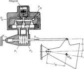
The correction of the microlauncher trajectory during the powered flight phase is due to TVC. The system is composed of a movable nozzle (divergent) and an electro-hydraulic actuator, as illustrated in Fig. 6. In this work, it is assumed that the inertia of the nozzle and its mass are negligible for the rocket.
In this work, the first-order actuator model of Silva (2014) is used, defined as:
where Ka is the passband of the actuator.
GNC system design and validation
The functional requirements and the respective verification meaning in Tables 1 and 2 are a guide to the design and validation of the GNC system of the first body of a microlauncher. These requirements are the cornerstone of guaranteeing that the embedded control system accomplishes its mission goals in the powered flight phase with stability, responsiveness, and robustness. Two significant milestones were passed in the development process. In the first, a pitch stabilization control strategy was developed and tested using MATLAB simulations, in which the objective was to validate controller performance and theoretical assumptions. To enable HIL simulations and conduct real-time performance analysis under representative flight conditions, the second stage involved implementing the verified control logic on an embedded hardware platform.
Attitude control
In this work, PID control is employed owing to its universality and widespread use, e.g., in LV attitude control (Campos 2004; Lustig 2016; Silva 2014). The focus is on gain calculations for pitch stabilization, since the derivation for other axes would be analogous. The controller design employs a reduced rigid-body model, retaining the primary dynamics and facilitating calculations. Actuator and sensor dynamics are initially neglected because they are fast in comparison to rigid-body dynamics and are addressed through gain and phase margins (Campos 2004). Gain scheduling is employed to modify Kp, Ki, and Kd as a function of time to make adjustments for vehicle parameter variations. Because the system is quasi-invariant over small time intervals, stability analysis is conducted at an instant through the LQ method. LQ method for gains calculations
The LQ method aims to minimize the cost function:
where Q and R are weight matrices that change the relative weight of states (x(t)) and control effort (δ(t)). Their values are chosen empirically. This technique is based on finding a reference model of the closed-loop system for an instant of greater aerodynamic influence, varying the matrices Q and R (Campos 2004).
Considering the reduced model in Eq. 6, the transfer function of the controlled system is given by:
When writing Eq. 9 in the form of a differential equation, in the time domain, the following is obtained:
The next step is to integrate Eq. 10, as:
and writing it in matrix form, as:
Analyzing Eq. 9, it can be correlated with an equation of the type:
Thus, by analogy, one gets the values of Kp, Kp, and Kd scaled in time (Campos 2004)
RESULTS
The microlauncher controller was validated with a comprehensive “full” model that included features omitted in the gain calculation procedure. Validation outcomes were scrutinized utilizing a 3D trajectory simulation, augmented by traditional performance plots. 3D visualization was presented using the FlightGear simulator, with the interface between the simulator and Simulink handled using MATLAB’s Aerospace Toolbox.
The vehicle data were taken from Silveira (2014), and reference trajectory angles were generated using Aerospace Trajectory Optimization Software (ASTOS), which is a commercial simulation and optimization software for space vehicle trajectories. The analysis focuses on pitch and yaw control during the first-stage flight. Simulations were run at a 100 Hz sampling frequency so that the controller would be approximated as continuous.
Attitude control
LQ method
Before calculating the Q and R matrices, some performance requirements were defined as follows:
Rise time ≈ 1 s;
Overshoot ≈ 20%.
The control design was based on system dynamics at the time of maximum dynamic pressure, as this represents the point of highest aerodynamic loading on the vehicle. This critical instant occurs approximately 60 s into the flight. The weighting matrices Q and R were selected according to standard LQR design guidelines, following state normalization and Bryson’s rule to balance state regulation accuracy and control effort while ensuring closed-loop stability. The resulting weighting matrices are given by:
Consequently, the values of the variables of the scaling of gains when using Eq. 14 are given as:
Gains evaluation performance for the instant of maximum dynamic pressure
With the Q and R matrices corresponding to the instant of maximum dynamic pressure, gains , and are obtained. The controlled system step response for the instant of maximum dynamic pressure is shown in Fig. 7. Analyzing the graph, the response satisfies the established parameters for rise time and overshoot, approximately 1 s and 20%, respectively.

Gain scheduling
With the scaling variables (ωn, α, and ζ), the values of Kp, Ki, and Kd were calculated for the entire duration of the flight, which can be seen in Fig. 8.

Controller validation
For the validation of the full model, the complete nonlinear model was used, where U is a time-varying parameter. Regarding the actuator dynamics, Ka was set to 28 (Silva 2014). The numerical integration method chosen was the fourth-order Runge-Kutta.
Simulations
Next, the complete simulation results for the proposed launcher using the calculated control gains are presented. It is important to note that, in the yaw plane, the angle values remained zero throughout the flight, meaning no attitude correction was required. As a result, plots of angles and control commands are shown only for the pitch plane.
Figure 9 shows the simulation result for the nozzle deflection. As per the design specifications, the nozzle deflection angle is limited to three degrees. It can be seen that the actuator was far from saturation for almost the entirety of the flight. Actuator saturation is observed only near the end of the burn, which corresponds to a flight phase in which the thrust level rapidly decreases, and the attitude control system is typically deactivated in real flight conditions. In this phase, alternative control strategies are commonly adopted to limit angular rates and lateral acceleration, preventing excessive growth of the angle of attack prior to stage separation and second-stage ignition. A detailed description of these strategies is beyond the scope of this work. With the requirement fulfilled, the results of the simulations in MATLAB and HIL are presented for the pitch angles, trajectory traveled, and longitudinal velocity of the microlauncher.

Figure 10 displays the pitch attitude control response over time. The rocket’s pitch data are relative to the inertial system. The designed attitude control managed to correct the pitch throughout the flight.

Figure 11 refers to the longitudinal velocity of the vehicle over time, and Fig. 12 presents the result of the trajectory in the x, y, and z axes being represented in the East-North-Up (ENU) system.


Flight path presentation with the FlightGear simulator
To improve the visualization of the flight path in the simulations, providing an alternative to the graphical option, the FlightGear Flight Simulator was used for a 3D visual approach.
The software allows various configurations, from changing the physics of the simulator to choosing aircraft and locations around the world. MATLAB, via Aerospace Toolbox, provides a good interface for communicating with FlightGear.
For the simulations carried out in this work, the Russian rocket Vostok K was chosen to represent the microlauncher and the Alcântara Launch Center (Centro de Lançamento de Alcântara) as the take-off location, through the choice of the SNCW airport.
CONCLUSION
The launch industry into space is undergoing intensified development, driven by the increased demand for responsive deployment concepts and small satellite missions. In these highly competitive circumstances, the development of LVs, particularly microlaunchers, must be based on optimized, cost-effective, and reliable system designs to remain attractive in the marketplace. In this context, reliable and cost-effective onboard systems play a central role in ensuring competitiveness.
This work presented the simulation and validation of a control architecture for the first stage of a microlauncher, focusing on the integration of GNC algorithms in a real-time embedded system. The system design took into account the flight dynamics and operating constraints of a solid-propellant LV to provide reliable performance over the powered flight phase. To facilitate control system synthesis, a nonlinear rigid-body model of the vehicle was developed and then linearized. A gain-scheduled PID controller was designed using an LQ-based procedure, and the controller design was carried out at the maximum dynamic pressure condition, which occurs at approximately 60 s of flight, resulting in gains of Kp = 16.15, Ki = 8.63, and Kd = 2.43. At this operating point, the closed-loop response satisfied the specified design requirements, with approximately 1 s rise time and 20% overshoot. Actuator dynamics were also modeled and included in the simulation environment for greater realism in the embedded implementation.
Validation was performed through HIL and SIL simulations for the first-stage powered flight. The comparisons with the ASTOS reference trajectory showed consistent pitch response behavior in MATLAB and HIL, indicating satisfactory trajectory tracking and attitude stabilization. The nozzle deflection remained within the ±3° design limit for almost the entire flight, with actuator saturation observed only near the end of the burn. Furthermore, real-time execution at 100 Hz demonstrated the computational feasibility of the proposed embedded implementation. The hardware implementation of the GNC design enhances the integrity of the integration test and fills a gap present in most previous research. In addition, the use of a 3D simulation environment to depict the flight trajectory, alongside conventional two-dimensional plots, complements the quantitative analysis by offering a more intuitive qualitative interpretation of the vehicle motion.
Despite these encouraging results, some limitations of this study should be acknowledged. The analysis and validation are restricted to the first-stage powered flight of the microlauncher, the actuator dynamics are represented by a simplified model suitable for control design purposes, and the HIL platform employed corresponds to a laboratory prototype intended for functional verification rather than flight-qualified hardware. These assumptions are appropriate for early-stage development and integration testing, but further refinement and validation are required for full mission-level and flight-ready applications.
In addition to the simulation and validation results, this study also proposed functional requirements and verification tables for the microlauncher OBC to synthesize system requirements and guide validation activities. These structured definitions both serve the design process and the ultimate qualification methods for small LV avionics. Overall, the methodology and results presented here provide a solid and adaptable foundation for the development of onboard systems for microlaunchers and other small satellite LVs.
ACKNOWLEDGEMENTS
The authors acknowledge Fundação de Amparo à Pesquisa e ao Desenvolvimento Científico e Tecnológico do Maranhão (FAPEMA) and Prof. Dr. Leonardo Gonsioroski for their support and assistance related to this research.
-
DECLARATION OF USE OF ARTIFICIAL INTELLIGENCE TOOLS
No artificial intelligence tools were used in the preparation of this manuscript.
-
FUNDING
Fundação de Amparo à Pesquisa e ao Desenvolvimento Científico e Tecnológico do MaranhãoGrant No: BM-AEROESPACIAL-01745/17
-
Peer Review History
Single Blind Peer Review.
DATA AVAILABILITY STATEMENT
The data will be available upon request.
REFERENCES
-
Afilipoae TP, Neculăescu AM, Onel AI, Pricop MV, Marin A, Perșinaru AG, Ioniță C, Bădescu R, Zărnescu O, Dumitrescu A, et al (2018) Launch vehicle-MDO in the development of a microlauncher. Transp Res Procedia 29:1-11. https://doi.org/10.1016/j.trpro.2018.02.001
» https://doi.org/10.1016/j.trpro.2018.02.001 -
Ansari U, Bajodah AH (2015) Generalized dynamic inversion scheme for satellite launch vehicle attitude control. IFAC-PapersOnLine 48(9):114-119. https://doi.org/10.1016/j.ifacol.2015.08.069
» https://doi.org/10.1016/j.ifacol.2015.08.069 -
Barbosa ECG, Góes LC, Xavier TS (2018) Hydraulic pressure fed system using helium gas and fast electro-hydraulic actuator applied to Brazilian sounding rockets and microsatellite launchers. Paper presented 2018 4th Workshop on Innovative Engineering for Fluid Power. ABIMAQ; São Paulo, Brazil. Url: https://ep.liu.se/ecp/156/002/ecp18156002.pdf
» https://ep.liu.se/ecp/156/002/ecp18156002.pdf -
Bauer T, Conger RC, Wertz JR, Sarzi-Amadé N (2010) Design, performance, and responsiveness of a low-cost micro-satellite launch vehicle. Paper presented 2010 8th Responsive Space Conference. USASMDC; Los Angeles, USA. Url: https://ep.liu.se/ecp/156/002/ecp18156002.pdf
» https://ep.liu.se/ecp/156/002/ecp18156002.pdf -
Bôas DJFV, Souza CHM, da Motta Silva F, Moraes A (2020) Proposal of low cost launchers for scientific missions using cubesats. Adv Space Res 66(1):162-175. https://doi.org/10.1016/j.asr.2019.12.012
» https://doi.org/10.1016/j.asr.2019.12.012 -
Bozic O, Poppe G, Porrmann D (2014) An advanced hybrid rocket engine for an alternative upper stage of the Brazilian VLM 1 LEO launcher. Paper presented 65th International Astronautical Congress. IAF; Toronto, Canada. Url: https://elib.dlr.de/92805/
» https://elib.dlr.de/92805/ -
Campos DC (2004) Estudo de um método para cálculo de ganhos da malha de controle de atitude de um lançador de satélites (master’s thesis). São José dos Campos: Instituto Nacional de Pesquisas Espaciais. In Portuguese. Url: http://mtc-m16.sid.inpe.br/col/sid.inpe.br/jeferson/2004/05.14.10.44/doc/publicacao%20(2).pdf
» http://mtc-m16.sid.inpe.br/col/sid.inpe.br/jeferson/2004/05.14.10.44/doc/publicacao%20(2).pdf -
Cás PL, Veras CA, Shynkarenko O, Leonardi R (2019) A Brazilian space launch system for the small satellite market. Aerospace 6(11):123. https://doi.org/10.3390/aerospace6110123
» https://doi.org/10.3390/aerospace6110123 - Cornelisse JW, Schoyer H, Wakker KF (1979) Rocket propulsion and spaceflight dynamics. London: Pitman.
-
Crisp N, Smith K, Hollingsworth P (2014) Small satellite launch to LEO: a review of current and future launch systems. Trans Jpn Soc Aeronaut Space Sci Aerosp Technol Jpn 12(ists29):Tf39-Tf47. https://doi.org/10.2322/tastj.12.Tf_39
» https://doi.org/10.2322/tastj.12.Tf_39 -
Dupont C, Tromba A, Missonnier S (2019) New strategy to preliminary design space launch vehicle based on a dedicated MDO platform. Acta Astronaut 158:103-110. https://doi.org/10.1016/j.actaastro.2018.04.013
» https://doi.org/10.1016/j.actaastro.2018.04.013 -
Duret F, Fabrizi A (1999) VEGA, a small launch vehicle. Acta Astronaut 44(7-12):507-514. https://doi.org/10.1016/S0094-5765(99)00090-9
» https://doi.org/10.1016/S0094-5765(99)00090-9 -
Eramo V, Lavacca FG, Valente F, Pisculli A, Caporossi S (2018) Simulation and experimental evaluation of a flexible time triggered ethernet architecture applied in satellite nano/micro launchers. Aerospace 5(3):84. https://doi.org/10.3390/aerospace5030084
» https://doi.org/10.3390/aerospace5030084 -
Ghorbani M, Pasand M, Bayati AG, Baheri N (2018) Real-time hardware-in-the-loop test for a small upper stage embedded control system. Paper presented 2018 Real-Time and Embedded Systems and Technologies. IEEE; Tehran, Iran. https://doi.org/10.1109/RTEST.2018.8397164
» https://doi.org/10.1109/RTEST.2018.8397164 - Greensite AL (1970) Analysis and design of space vehicle flight control systems. Vol. 2. New York: Spartan Books.
-
Gupta SC, Suresh BN (1988) Development of navigation guidance and control technology for Indian launch vehicles. Sadhana 12:235-249. https://doi.org/10.1007/BF02812030
» https://doi.org/10.1007/BF02812030 -
Horvath G, Jones G, Joshi R (2009) A model-based approach to verification of spacecraft software using the SPIN model checker. Paper presented 2009 AIAA Space Conference & Exposition. AIAA; Pasadena, USA. https://doi.org/10.2514/6.2009-6594
» https://doi.org/10.2514/6.2009-6594 -
Lanre AM, Fashanu TA, Osheko AC (2014) Parameterization of micro satellite launch vehicle. J Aeronaut Aerosp Eng 3(2). Url: https://www.longdom.org/open-access/parameterization-of-micro-satellite-launch-vehicle-10202.html
» https://www.longdom.org/open-access/parameterization-of-micro-satellite-launch-vehicle-10202.html -
Lustig M (2016) Modeling of launch vehicle during the lift-off phase in atmosphere (undergraduate thesis). Prague: Czech Technical University in Prague. Url: https://dspace.cvut.cz/server/api/core/bitstreams/3c296cc7-f5fb-4cd3-a1f8-fe31956fa980/content
» https://dspace.cvut.cz/server/api/core/bitstreams/3c296cc7-f5fb-4cd3-a1f8-fe31956fa980/content -
Mammen O, Nair VV, Sreenath DI (1990) Dynamic test bed for the on-board computer system of a space launch vehicle. Microprocess Microsyst 14(8):525-530. https://doi.org/10.1016/0141-9331(90)90052-W
» https://doi.org/10.1016/0141-9331(90)90052-W -
Martínez JR, Cruz-Mendoza JÁDL, Vázquez-Martínez E, Cruz DRDL, Guerrero A (2024) Development of an optimized induction melting system for fabricating paraffin fuel grains for hybrid rocket propulsion. J Aerosp Technol Manag 16:e1350. https://doi.org/10.1590/jatm.v16.1350
» https://doi.org/10.1590/jatm.v16.1350 -
Mata HOD, Falcão JBP, Avelar AC, Carvalho LMMDO, Azevedo JLF (2017) Visual experimental and numerical investigations around the VLM-1 microsatellite launch vehicle at transonic regime. J Aerosp Technol Manag 9:179-192. https://doi.org/10.5028/jatm.v9i2.676
» https://doi.org/10.5028/jatm.v9i2.676 -
Motta F, Pessoa Filho JB, de Oliveira Moraes A (2024) Is there a market for micro-launch vehicles? Space Policy 70:101629. https://doi.org/10.1016/j.spacepol.2024.101629
» https://doi.org/10.1016/j.spacepol.2024.101629 -
Moura WDM, dos Santos CR, Freitas MJDS, Pinto AC, Simões LP, Moraes A (2024) MicroGravity Explorer Kit (MGX): an open-source platform for accessible space science experiments. Aerospace 11(10):790. https://doi.org/10.3390/aerospace11100790
» https://doi.org/10.3390/aerospace11100790 -
Nair AP, Selvaganesan N, Lalithambika VR (2016) Lyapunov based PD/PID in model reference adaptive control for satellite launch vehicle systems. Aerosp Sci Technol 51:70-77. https://doi.org/10.1016/j.ast.2016.01.017
» https://doi.org/10.1016/j.ast.2016.01.017 -
Perondi LF (2023) The coming of age of space satellite industry: transitioning from a growth to a maturity life cycle phase. J Aerosp Technol Manag 15:e0323. https://doi.org/10.1590/jatm.v15.1291
» https://doi.org/10.1590/jatm.v15.1291 -
Pinto AC, dos Santos CR, Pinho M, de Oliveira Moraes A, Medeiros R, Vilela SS (2025) Hybrid DCT-modal analysis-based compression of vibration signals for telemetry in sounding rockets. Meas Sci Technol 36(4). https://doi.org/10.1088/1361-6501/adc326
» https://doi.org/10.1088/1361-6501/adc326 -
Pinto AC, Maciel MD, Pinho MS, Medeiros RR, Moraes AO (2023) Evaluation of lossy compression algorithms using discrete cosine transform for sounding rocket vibration data. Meas Sci Technol 34(1):015117. https://doi.org/10.1088/1361-6501/ac97fe
» https://doi.org/10.1088/1361-6501/ac97fe -
Samuel AA, Jayalal N, Valsa B, Ignatious CA, Zachariah JP (2013) Software fault injection testing of the embedded software of a satellite launch vehicle. IEEE Potentials 32(5):38-44. https://doi.org/10.1109/MPOT.2012.2236150
» https://doi.org/10.1109/MPOT.2012.2236150 -
Sankar KS, Samuel AA, Jayalal N, Gopalakrishnan T (2018) Independent verification and validation strategy of Real-Time EXecutive (REX) software of onboard computers of satellite launch vehicle. Paper presented 2018 2nd International Conference on Inventive Systems and Control. IEEE; Coimbatore, India. https://doi.org/10.1109/ICISC.2018.8399070
» https://doi.org/10.1109/ICISC.2018.8399070 -
Sarhadi P, Yousefpour S (2015) State of the art: hardware in the loop modeling and simulation with its applications in design, development and implementation of system and control software. Int J Dyn Control 3:470-479. https://doi.org/10.1007/s40435-014-0108-3
» https://doi.org/10.1007/s40435-014-0108-3 -
Silva AG (2014) Análise e projeto de sistemas de controle de atitude para o veículo lançador de satélites (VLS) (master’s thesis). São José dos Campos: Instituto Nacional de Pesquisas Espaciais. In Portuguese. Url: http://mtc-m21b.sid.inpe.br/col/sid.inpe.br/mtc-m21b/2014/03.06.16.40/doc/publicacao.pdf
» http://mtc-m21b.sid.inpe.br/col/sid.inpe.br/mtc-m21b/2014/03.06.16.40/doc/publicacao.pdf -
Silveira G (2014) Desenvolvimento de uma ferramenta computacional para simulação de voo de veículos lançadores (master’s thesis). São José dos Campos: Instituto Nacional de Pesquisas Espaciais. In Portuguese. Url: http://mtc-m21b.sid.inpe.br/col/sid.inpe.br/mtc-m21b/2014/07.02.21.27/doc/publicacao.pdf
» http://mtc-m21b.sid.inpe.br/col/sid.inpe.br/mtc-m21b/2014/07.02.21.27/doc/publicacao.pdf -
Silveira G, Fernandes SS (2023) Trajectory optimization of the Brazilian multistage launch vehicle microlauncher-1. J Braz Soc Mech Sci Eng 45(11):564. https://doi.org/10.1007/s40430-023-04490-6
» https://doi.org/10.1007/s40430-023-04490-6 -
Simões LP, dos Santos CR, Moraes A (2024) A proposed methodology for assessment of Li-ion cell suitability and safety for suborbital vehicle applications. Microgravity Sci Technol 36(3):24. https://doi.org/10.1007/s12217-024-10110-2
» https://doi.org/10.1007/s12217-024-10110-2 -
Sun BC, Park YK, Roh WR (2007) Hardware in the loop tests for upper stage control systems of Korean space launch vehicle. Paper presented 2007 International Conference on Control, Automation and Systems. IEEE; Seoul, South Korea. https://doi.org/10.1109/ICCAS.2007.4406713
» https://doi.org/10.1109/ICCAS.2007.4406713 -
Sun BC, Park YK, Roh WR, Cho GR (2010) Attitude controller design and test of Korea space launch vehicle-I upper stage. Int J Aeronaut Space Sci 11(4):303-312. https://doi.org/10.5139/IJASS.2010.11.4.303
» https://doi.org/10.5139/IJASS.2010.11.4.303 -
Tavares A (2019) Desenvolvimento e simulação de um computador de bordo para o veículo lançador de microssatélites (MICROLAUNCHER) (master’s thesis). São Luís: Universidade Estadual do Maranhão. Url: https://repositorio.uema.br/bitstream/123456789/1252/1/Dissertação-Adalberto-Tavares-Jr-v2v-1.pdf
» https://repositorio.uema.br/bitstream/123456789/1252/1/Dissertação-Adalberto-Tavares-Jr-v2v-1.pdf -
Wekerle T, Pessoa Filho JB, Costa LEVLD, Trabasso LG (2017) Status and trends of smallsats and their launch vehicles – An up-to-date review. J Aerosp Technol Manag 9(3):269-286. https://doi.org/10.5028/jatm.v9i3.853
» https://doi.org/10.5028/jatm.v9i3.853 -
Wunderlin N, Martin DJ, Pitot J, Brooks MJ (2018) Design options for a South African small-satellite launch vehicle. Paper presented 2018 Joint Propulsion Conference. AIAA; Cincinnati, USA. https://doi.org/10.2514/6.2018-4462
» https://doi.org/10.2514/6.2018-4462
Edited by
-
Section editor:
Luiz Martins-Filho https://orcid.org/0000-0002-7287-5979

 Source: Adapted from Microlauncher (2017).
 Source: Adapted from
  Source: Adapted from
  Source: Adapted from
  Source: Adapted from
  Source: Adapted from
  Source: Elaborated by the authors.
 Source: Elaborated by the authors.
 Source: Elaborated by the authors.
 Source: Elaborated by the authors.
 Source: Elaborated by the authors.
 Source: Elaborated by the authors.