
 Experimental and Numerical Study on Optimization of Zigzag Rib Topologies for Trailing-Edge Morphing Wings for Low-Speed Applications
ABSTRACT
This study aimed to propose different zigzag rib topologies for a trailing-edge morphing wing for low-speed applications. This study aimed to determine the best zigzag rib topology in terms of stiffness and safety factor. Numerical analysis was carried out using ANSYS under linear-static conditions for different test cases, such as rib topologies, rib thicknesses, deflection angles, and materials. A total of 81 test cases were studied with a point load applied at the trailing edge of each rib topology in each test to obtain the stiffness and safety factor. Experimental studies were also conducted to evaluate the mass and shapes of 3D-printed ribs. The findings revealed that thermoplastic polyurethane ribs with a 5 mm thickness exhibited moderate stiffness and a good safety factor, with no failure occurring under the applied conditions. Additionally, there was a perfect match between numerical and experimental results in terms of the mass and shape of the topologies under different test cases.
Keywords
Morphing wings; Trailing edges; Aerodynamic loads; Stiffness; Thermoplastic polyurethane; Computerized simulation
INTRODUCTION
Aerodynamic adaptability is pivotal for navigating flight dynamics, whether it is an airborne animal or an aircraft. It hinges on fine-tuning lift-generating surfaces to manipulate aerodynamic forces. Moreover, the capacity to customize the aerodynamic properties of these surfaces exceeds that of the conventional control methods, yielding significant performance enhancements. The different morphing wing concepts such as variable camber, variable thickness, leading edge morphing, trailing-edge morphing, chordwise morphing, wing-level morphing, spanwise morphing, wing twisting, hybrid morphing etc., have promising improvement in aerodynamic characteristics (Li et al. 2018) and provided a framework for the design of morphing wings for unmanned aerial vehicles (UAVs) with theoretical and technical references (Chu et al. 2022). Kinematic and flight tests of the fixed-flapping hybrid morphing wing aerial vehicle (FFWAV) revealed coupled pitch and roll angles, while computational fluid dynamics (CFD) simulations showed that the flapping wing section provided over 50% of the lift by enhancing the fixed wing’s lift through edge vortex generation (Kan et al. 2023). Force analysis and optimization methods were employed on novel designs to ensure structural integrity and efficiency, and the approach was validated through fabricated prototypes with and without skins (Wang et al. 2020). The zigzag wing box concept was introduced, enabling a 44% variation in wingspan through a combination of rigid and morphing sections. Incorporated into a medium-altitude long-endurance UAV wing, the concept enhanced operational performance and facilitated roll control (Ajaj et al. 2013). The blending of continuous variable spanwise bend, twist, and sweep, along with hybrid span morphing wings, demonstrated the potential for improved aerodynamic performance (Boston et al. 2022; Yang et al. 2023).
The camber morphing has a direct effect on the aerodynamic characteristics due to its adaptive camber-wise shape change. The study designed a seamless morphing trailing edge structure using parametric finite element models and demonstrated that it could sustain 0.015 MPa loads while achieving ±15° camber changes (Cheng et al. 2023). A mechanical solution for a variable camber trailing edge was developed, achieving 5° upward to 15° downward deflection through parametric optimization and fiber Bragg grating (FBG) sensor monitoring, demonstrating effective morphing capability (Shi et al. 2023). The effects of fishbone active camber morphing on wing-in-ground effect were investigated using CFD at a Reynolds number of 320,000, revealing improved aerodynamic efficiency through optimized morphing parameters (Clements and Djidjeli 2023). The morphing wing was developed to delay stall by flexibly deflecting the trailing edge. Results showed smaller lift coefficients during deflection at low angles, while higher deflection rates increased lift coefficients at critical stall angles (Kan et al. 2020). An autonomous morphing wing concept using six camber morphing modules was investigated, and a fluid-structure interaction optimization tool was developed, and validated the design through measurements and characterization of mechanical losses (Mkhoyan et al. 2022). A 3D bionic flap inspired by spanwise morphing on an S809 airfoil was studied through aerodynamic simulations. Results showed that spanwise morphing flaps significantly improved lift, reduced drag, delayed flow separation, and enhanced aerodynamic performance compared to conventional flaps (Akhter et al. 2022). Numerical simulations and lab experiments carried out on trailing-edge designs for tidal turbine blades revealed that camber effects and material stiffness impact deformation and failure (Maguire et al. 2024). Numerical analyses in ANSYS compared simplified and realistic loading cases. Experimental tests assessed displacement and failure loads, with a scanning electron microscope (SEM) for fracture analysis. Truss configurations proved structurally efficient, with stiffness as the primary design constraint over strength (Carneiro and Gamboa 2019). Camber morphing turbine blades also resulted in improved aerodynamic efficiency (Bishay et al. 2024). A study used numerical simulations and flexible multi-body dynamics to analyze unsteady aerodynamics and aeroelastic behavior in variable-sweep and folding wings, revealing that dynamic hysteresis in lift coefficients and stability are significantly influenced by additional velocity, flow hysteresis, viscosity, and folding/unfolding rates (Hu et al. 2016; Zeng et al. 2023). Computational fluid dynamics (CFD) simulations demonstrated improved lift coefficient and lift-drag ratio compared to the base airfoil and traditional flap-based wings, with reduced drag during morphing (Hao et al. 2021; Kodigaddi et al. 2022; 2024).
The morphing structure played a crucial role in achieving the desired shape during actuation. Recent trends showed promising results in developing complex morphing structures using additive manufacturing processes with appropriate materials. A comprehensive review showed that the utilization of additive manufacturing technologies in the aerospace and automotive industries led to the accurate printing of complex shapes (Alami et al. 2023). Among the three additive manufacturing technologies, selective laser sintering (SLS), fused deposition modeling (FDM), and continuous filament fabrication (CFF), the SLS materials exhibited significantly higher maximum stresses, with a focus on mechanical testing for airframe parts (Šančić et al. 2023). Also, morphing designs were manufactured with a budget-friendly FDM 3D printer using thermoplastic polyurethane (TPU), which successfully balanced the stiffness of the metamaterial with the flexibility of the wing base (Zhilyaev et al. 2022). To accommodate shape changes, recent developments demonstrated the use of polymer-based skins for morphing wing applications (Ahmad et al. 2024).
Advancements in morphing wing technologies showed promise for enhanced aerodynamic performance and structural efficiency, addressing various challenges through innovative designs and rigorous analyses. While many studies reported the effectiveness and potential of adopting innovative designs in morphing wing technologies, extensive research on achieving a smooth deformation profile was also carried out. In this study, an attempt was made to propose a novel rib design for trailing-edge morphing applications. The originality of the study lies in identifying the zigzag rib topologies best suited for trailing-edge morphing wing applications obtained through additive manufacturing. This facilitated the development of more complex and effective rib topologies and optimized the rib topologies using additive manufacturing and finite element analysis (FEA).
Zigzag rib topology
Airfoil and rib selection
The NACA 2412 airfoil is commonly chosen as a reference airfoil for the study due to its outstanding aerodynamic behavior, well-defined geometry, and widespread use in morphing wing applications (Amini et al. 2015; Guerrero 2009; Shen et al. 2023).
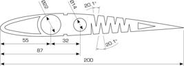
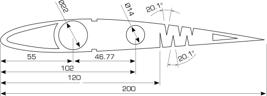
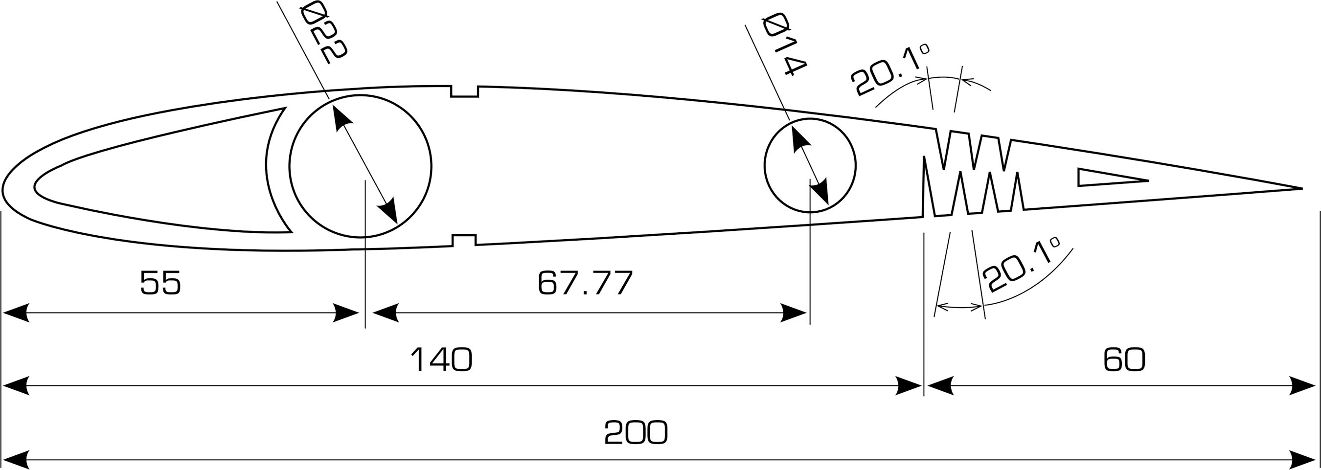
The three morphing wing topologies studied here consist of two rows of zigzag rib patterns, strategically designed to minimize the force exerted during camber adjustment and to achieve a smooth change in the camber and shape of the airfoil at the trailing edge. Each morphing topology comprises a rigid section, serving as the fixed part of the rib, and a flexible section with a zigzag pattern, facilitating the change of shape at the trailing edge.
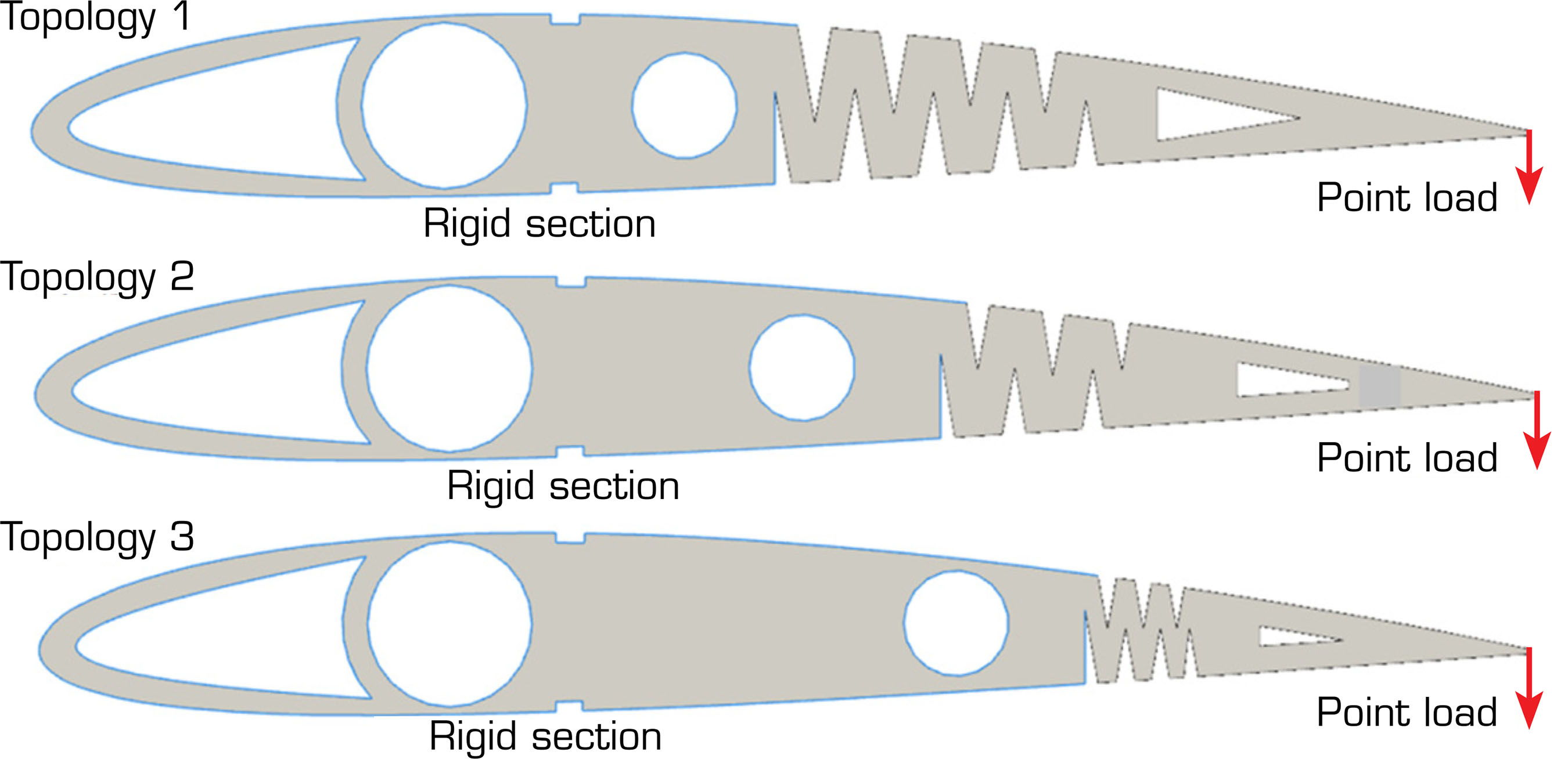
Three rib topologies are modeled with different percentages of rigid and flexible sections, namely zigzag rib topology 1 (50:50), zigzag rib topology 2 (60:40), and zigzag rib topology 3 (70:30), as shown in Figs. 1–3, respectively. All dimensions are in mm. Each zigzag rib includes a hole for placing the main circular spar with a diameter of 22 mm, positioned at 27.5% of the chord in all topologies. Another hole is located at 43.5%, 51.18%, and 61.5% of the chord of topologies 1, 2, and 3, respectively, for placing the secondary spar with a diameter of 14 mm. Three different thicknesses: 2.5 mm, 5 mm, and 7.5 mm; three different deflection angles: +5°, +10 °, and +15°; and three different materials for the zigzag ribs are considered: TPU, polylactic acid (PLA), and acrylonitrile butadiene styrene (ABS).

Material selection
Thermoplastic polyurethane (TPU), PLA, and ABS were considered for the study. TPU was highly flexible and elastic, with excellent stretch and recovery properties, while PLA was relatively stiff and brittle compared to TPU, offering limited flexibility. ABS fell between TPU and PLA in terms of rigidity and flexibility, providing moderate flexibility. TPU exhibited high tensile strength and toughness, making it resilient to impacts and deformation. PLA had moderate strength and toughness, suitable for general-purpose applications, but was less durable than TPU. ABS offered good impact resistance and strength, making it suitable for structural components. Given the primary requirement for a lightweight structure with minimal force needed to operate the zigzag rib for improved aerodynamic performance, TPU emerged as the most suitable material. Its flexibility, resilience, and relatively low weight made it ideal for achieving the desired performance characteristics while minimizing energy consumption during operation (Cantrell et al. 2017; Farah et al. 2016; Xu et al. 2020). Table 1 indicates the properties of the materials used.
Structural analysis
The purpose of this research was to carry out structural analysis on three different wing topologies made of three different materials under various load conditions. From these results, the selection of the best-suited topology was determined by considering the total deformation, directional deformation, equivalent stresses, and safety factors for the conditions mentioned above. Structural analysis was conducted using the structural analysis software tool ANSYS Workbench (R2022) under linear-static conditions. The blue-colored line shown in Fig. 4 indicates the rigid section of the zigzag rib, while the red-colored line indicates the location and the concentrated load applied. In this study, the concentrated load acting at the trailing edge of the zigzag rib was estimated to obtain the required camber and shape of the airfoil for different trailing edge deflection angles. Upon applying the concentrated load, there was no failure, and the zigzag rib remained intact without any structural failure.

Mesh convergence
Mesh convergence ensured that the results obtained from the analysis were reliable and accurate, particularly in regions of interest, such as stress concentration areas or areas with complex geometry. Mesh convergence occurred when increasing the number of elements no longer significantly altered the results. Mesh suitability was evaluated using an element quality index, ranging from 0 to 1. Both hexahedral (HEX) and tetrahedral (TET) mesh elements were commonly used for finite element analysis (FEA). HEX meshes, including HEX8, HEX20, and HEX27, offered higher accuracy and computational efficiency. However, TET meshes, such as TET4, TET10, TET15, and TET20, provided greater flexibility and adaptability to complex geometries due to their TET shape. While HEX elements were ideal for regular geometries and structured meshes, TET elements were preferred for irregular geometries and unstructured meshes, offering varying levels of accuracy and mesh refinement to suit different simulation requirements (ANSYS 2016). Quadratic TET formulations, notably the TET10 element, presented a compelling alternative to HEX elements for simulating articular contact, offering a particularly well-suited solution for this type of analysis (Maas et al. 2016).
Considering this, meshes using different TET elements for all topologies were generated (sample mesh shown in Fig. 5), and a comparison was made between the different types of TET elements, as given in Table 2. The mesh convergence results showed that TET10 provided elements that achieved a good quality index with a very refined mesh.

Test cases
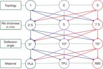
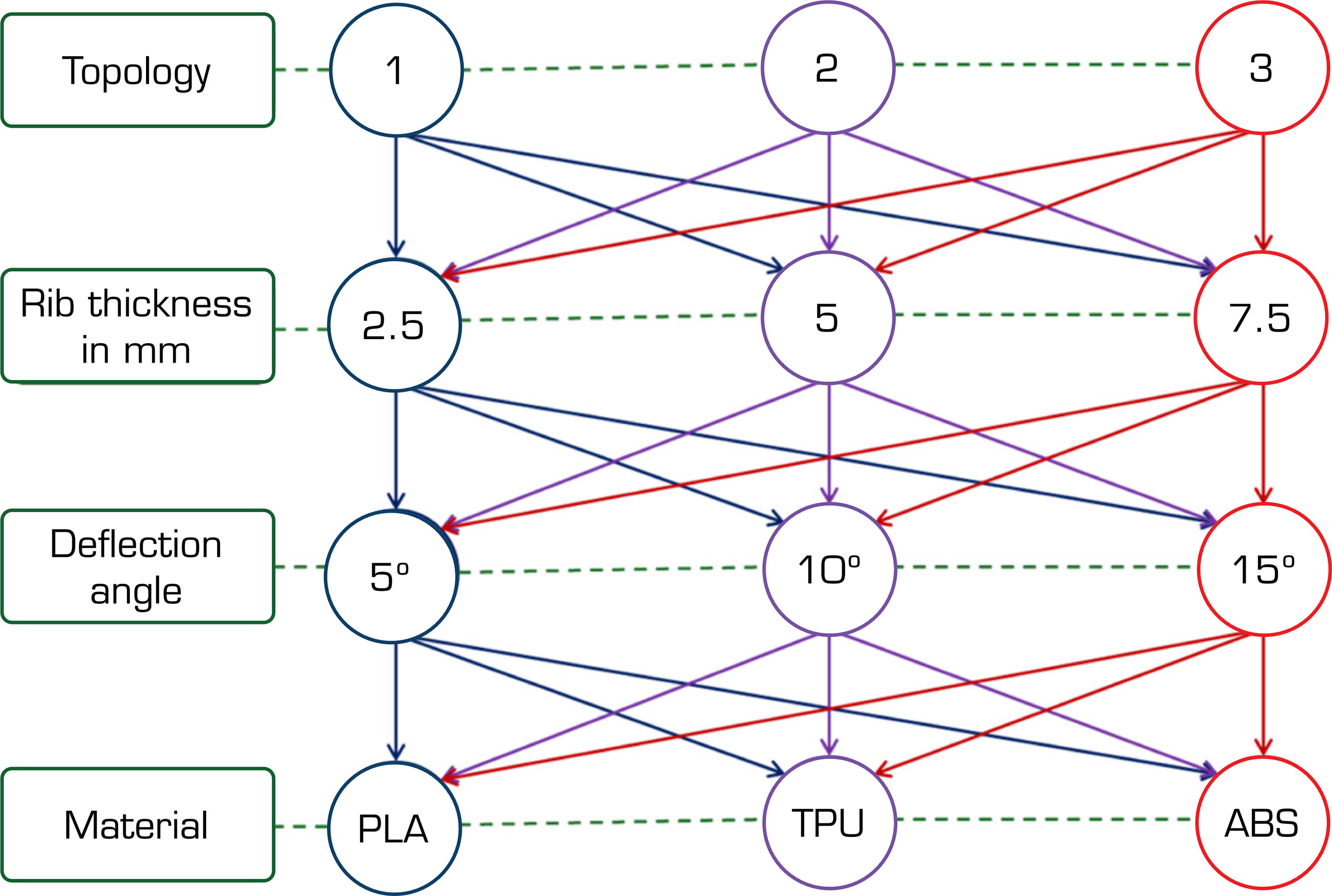
The test cases involved different combinations, including three topologies: 1, 2, and 3; three rib thicknesses: 2.5 mm, 5 mm, and 7.5 mm; three deflection angles: +5°, +10°, and +15°; and three rib materials: TPU, PLA, and ABS. Using response surface methodology (RSM) (Bezerra et al. 2008), a statistical and mathematical technique useful for modeling and analyzing problems, these combinations resulted in 81 test cases. The representation of test cases is as given in Fig. 6. Structural analysis was conducted for all these test cases to study the behavior of the different topologies.
RESULTS AND DISCUSSION
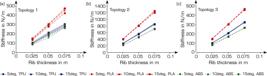
In Figure 7a, it was observed that for topology 1, PLA-made ribs with 2.5 mm and 5 mm thickness had approximately 33.33% more stiffness than TPU and ABS-made ribs. PLA-made ribs with 2.5 mm thickness had about 10.66% more stiffness than TPU- and ABS-made ribs. For topology 2, as shown in Fig. 7b, TPU and ABS-made ribs with 2.5 mm thickness offered relatively the same stiffness, whereas PLA-made ribs offered 50% more stiffness than TPU and ABS-made ribs. For ribs with 5 mm thickness, PLA-made ribs were 31.25% stiffer than TPU-made ribs and 27% stiffer than ABS-made ribs. For ribs with 7.5 mm thickness, PLA-made ribs were 33.33% stiffer than TPU-made ribs and 18.75% stiffer than ABS-made ribs. For topology 3, as shown in Fig. 7c, TPU- and ABS-made ribs with 2.5 mm thickness offered relatively the same stiffness, whereas PLA-made ribs offered 48% more stiffness than TPU- and ABS-made ribs. For ribs with 5 mm thickness, PLA-made ribs were 50% stiffer than TPU-made ribs and 25% stiffer than ABS-made ribs. For ribs with 7.5 mm thickness, PLA-made ribs were 36.84% stiffer than TPU-made ribs and 16.66% stiffer than ABS-made ribs. From the above discussion, it was concluded that topologies 1 and 3 offered less stiffness than topology 2, due to thicker zigzag rib patterns. The stiffness of the rib increased with thickness. PLA-made ribs offered higher stiffness than TPU and ABS-made ribs. This indicated that the force required to deflect at the trailing edge by PLA-made ribs was comparatively more than that required by TPU- and ABS-made ribs. The increase in thickness had a direct effect on this stiffness. PLA-made ribs became stiffer with increased thickness and deflection angle. This response remained similar for TPU and ABS-made ribs. TPU and ABS-made ribs with 5 mm thickness offered moderate stiffness, a response that was relatively consistent across all studied topologies.
From Fig. 8a, it was observed that for topology 1, the safety factor was relatively the same for all ribs with increasing deflection angles. PLA-made ribs with 7.5 mm thickness offered a higher safety factor than all other ribs for all deflection angles. TPU-made ribs offered a moderate safety factor, while ABS-made ribs offered the least safety factor for all deflection angles. ABS-made ribs had a safety factor less than 1.5 for all thicknesses and deflection angles, which was not acceptable. Comparatively, PLA-made ribs offered 21.42% more stiffness than TPU- and ABS-made ribs for all deflection angles. TPU-made ribs with 2.5 mm thickness had a safety factor greater than 1.5, whereas this value was more than 2 and 2.75 for ribs with 5 mm and 7.5 mm thicknesses, respectively, for all deflection angles. Improvements of 25% and 30% were observed for all deflection angles.
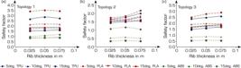
In Fig. 8b, for topology 2, the safety factor offered by PLA- and TPU-made ribs had similar values for different combinations studied. TPU-made ribs with 2.5 mm thickness offered a safety factor less than 1.5, whereas TPU-made ribs with 5 mm and 7.5 mm thicknesses and PLA-made ribs offered a safety factor greater than 1.5. The safety factor slightly increased with the increasing thickness of the rib. ABS-made ribs offered a safety factor of less than 1.5 for all combinations.
In Fig. 8c, for topology 3, the response to the safety factor from PLA and TPU-made ribs remained as in the previous test cases. However, the safety factor for all the cases was higher than 1.5. ABS-made ribs with all thicknesses offered a safety factor greater than 1.5 for only a +5° deflection angle, but for other deflection angles, it was less than 1.5.
From this analysis, it was concluded that TPU- and PLA-made ribs offered good safety factors across all combinations. Though PLA-made ribs provided a better safety factor than TPU-made ribs, they also exhibited higher stiffness, indicating that more force was required to deflect the topologies with PLA-made ribs compared to TPU-made ribs. Since the objective of this research was to recommend a topology with suitable thickness that would be flexible and not fail under the studied conditions, it was concluded that TPU-made ribs with a 5 mm thickness were well-suited, offering a good safety factor and moderate stiffness compared to PLA and ABS-made ribs.
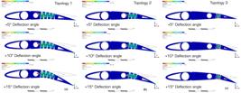
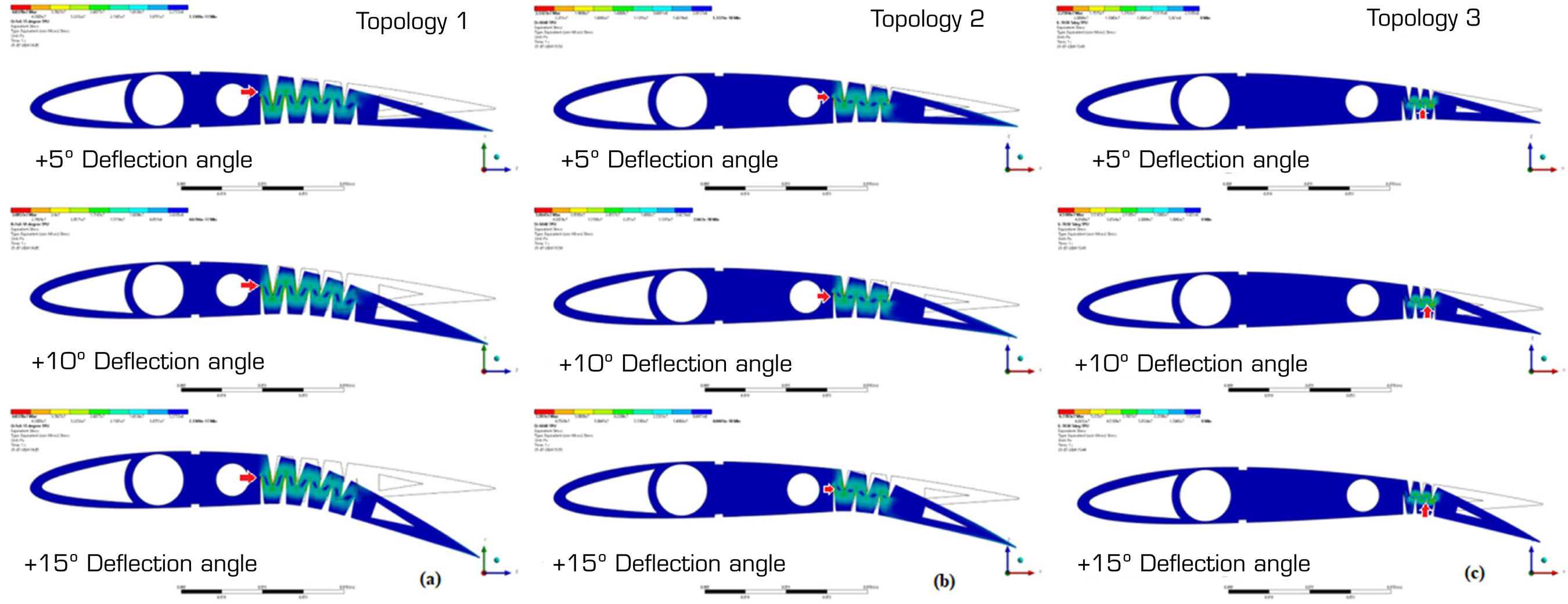
Figure 9 shows the equivalent stress induced in all topologies at +5°, +10°, and +15° deflection angles. It was observed that all topologies exhibited higher stress concentration regions at the zigzag rib patterns, as indicated by the red arrow. The lower stress concentration regions were located upstream of the spar and near the trailing edge. As concluded from the previous section, the TPU-made rib was best suited under the given conditions; therefore, further discussion on the response of PLA- and ABS-made ribs was not included. These ribs exhibited similar responses with varied stress values, while the regions of higher and lower stress concentration remained relatively consistent.
Development of ribs
The additive manufacturing of zigzag rib topologies using TPU involved the precise selection of parameters (Xu et al. 2020). A 100% infill density and a grid pattern ensured optimal strength and flexibility. A layer thickness of 0.1 mm and horizontal print orientation provided a smooth surface finish. Lower print speeds and an extruder temperature of 220 °C enhanced layer adhesion and mechanical properties. Post-processing techniques like sanding and polishing improved the final quality and appearance of the ribs, as shown in Fig. 10.

Zigzag rib mass and shape comparison
To evaluate the compatibility between the analysis results and the experimental results, parameters such as mass and shape were individually compared. Mass results from numerical (mn) and experimental (mexp) analyses were compared, as given in Table 3. It was observed that the mass values closely matched. The slight variation might have been due to porosity during the manufacturing process. However, this did not significantly affect the properties of the rib, as the difference was negligible.
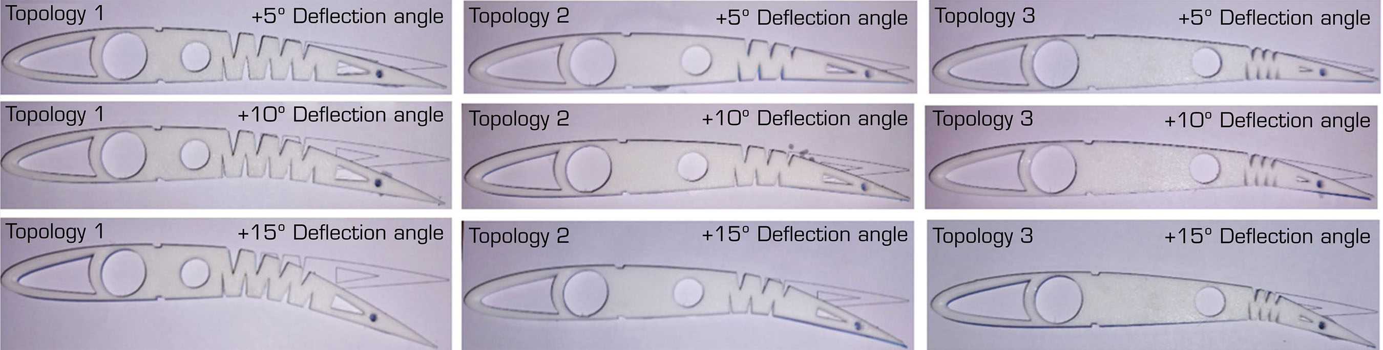
It was important to compare the shape of the topologies before and after the application of the point load. The numerical results, after applying the point load to achieve the required deflection angle, were analyzed. A comparison was made by cross-checking these results experimentally, as shown in Fig. 11. It was observed that the shape of all topologies matched perfectly. Since the objective of this study was to determine the proper rib structure for the maximum deflection angle of +15°, the failure points were not discussed.

CONCLUSION
This study effectively explored and evaluated various zigzag rib topologies for trailing-edge morphing wings, focusing on the integration of additive manufacturing and FEA. By analyzing different test cases that combined three rib topologies, thicknesses, deflection angles, and materials, the research identified the optimal rib structure in terms of stiffness, safety factor, and overall performance. The results confirmed that TPU ribs with a 5 mm thickness emerged as the most suitable choice. TPU ribs demonstrated moderate stiffness and a good safety factor, making them resilient under different loading conditions. The experimental results closely aligned with numerical predictions, with minor discrepancies attributed to manufacturing variations, which did not significantly impact rib performance. PLA and ABS materials were also evaluated, revealing that while PLA provided higher stiffness, TPU ribs offered a better balance of stiffness and safety factor. The study highlighted that TPU ribs with a 5 mm thickness were most effective, combining favorable mechanical properties and optimal performance for morphing applications. The originality of the research lay in its comprehensive approach to rib topology optimization using additive manufacturing, providing valuable insights for developing advanced morphing wing technologies. The study’s findings supported the use of TPU for achieving efficient and reliable wing morphing, contributing to the advancement of aerodynamic performance in trailing-edge applications.
ACKNOWLEDGMENTS
The authors acknowledge Nitte Meenakshi Institute of Technology, Bengaluru 560064, Karnataka, India, for supporting this research.
-
Peer Review History: Single Blind Peer Review.
-
FUNDING
Not applicable.
DATA AVAILABILITY STATEMENT
All datasets were generated or analyzed in the current study.
REFERENCES
-
Ahmad D, Parancheerivilakkathil MS, Kumar A, Goswami M, Ajaj RM, Patra K, Jawaid M, Volokh K, Zweiri Y (2024) Recent developments of polymer-based skins for morphing wing applications. Polym Test 135. https://doi.org/10.1016/j.polymertesting.2024.108463
» https://doi.org/10.1016/j.polymertesting.2024.108463 -
Ajaj RM, Saavedra Flores EI, Friswell MI, Allegri G, Woods BKS, Isikveren AT, Dettmer WG (2013) The Zigzag wingbox for a span morphing wing. Aerosp Sci Technol 28(1):364-375. https://doi.org/10.1016/j.ast.2012.12.002
» https://doi.org/10.1016/j.ast.2012.12.002 -
Akhter MZ, Ali AR, Omar FK (2022) Aerodynamics of a three-dimensional bionic morphing flap. Sustain Energy Technol Assess 52:102286. https://doi.org/https://doi.org/10.1016/j.seta.2022.102286
» https://doi.org/10.1016/j.seta.2022.102286 -
Alami AH, Ghani Olabi A, Alashkar A, Alasad S, Aljaghoub H, Rezk H, Abdelkareem MA (2023) Additive manufacturing in the aerospace and automotive industries: recent trends and role in achieving sustainable development goals. Ain Shams Eng J 14:11. https://doi.org/10.1016/j.asej.2023.102516
» https://doi.org/10.1016/j.asej.2023.102516 -
Amini Y, Emdad H, Farid M (2015) Adjoint shape optimization of airfoils with attached Gurney flap. Aerosp Sci Technol 41:216-228. https://doi.org/10.1016/j.ast.2014.12.023
» https://doi.org/10.1016/j.ast.2014.12.023 - ANSYS Inc. (2016) Meshing Advanced Techniques. PADT Lunch & Learn Series. ANSYS Inc.: Toronto, Canada.
-
Bezerra MA, Santelli RE, Oliveira EP, Villar LS, Escaleira LA (2008) Response surface methodology (RSM) as a tool for optimization in analytical chemistry. Talanta 76(5):965-977. https://doi.org/10.1016/j.talanta.2008.05.019
» https://doi.org/10.1016/j.talanta.2008.05.019 -
Bishay PL, McKinney T, Kline G, Manzo M, Parian A, Bakhshi D, Langwald A, Ortega A, Gagnon M, Funes Alfaro G (2024) SCAMORSA-1: a camber-morphing wind turbine blade with sliding composite skin. J Eng Res (Kuwait) 12(4). https://doi.org/10.1016/j.jer.2024.04.006
» https://doi.org/10.1016/j.jer.2024.04.006 -
Boston DM, Phillips FR, Henry TC, Arrieta AF (2022) Spanwise wing morphing using multistable cellular metastructures. Extreme Mech Lett 53. https://doi.org/10.1016/j.eml.2022.101706
» https://doi.org/10.1016/j.eml.2022.101706 -
Cantrell J, Rohde S, Damiani D, Gurnani R, Di Sandro L, Anton J, Young A, Jerez A, Steinbach D, Kroese C, Ifju P (2017) Experimental characterization of the mechanical properties of 3D printed ABS and polycarbonate parts. In: Yoshida S, Lamberti L, Sciammarella C, editors. Advancement of optical methods in experimental mechanics. Vol. 3. Cham: Springer. p. 89-105. https://doi.org/10.1007/978-3-319-41600-7_11
» https://doi.org/10.1007/978-3-319-41600-7_11 -
Carneiro PMC, Gamboa P (2019) Structural analysis of wing ribs obtained by additive manufacturing. Rapid Prototyp J 25(4):708-720. https://doi.org/10.1108/RPJ-02-2018-0044
» https://doi.org/10.1108/RPJ-02-2018-0044 -
Cheng G, Ma T, Yang J, Chang N, Zhou X (2023). Design and experiment of a seamless morphing trailing edge. Aerospace 10(3). https://doi.org/10.3390/aerospace10030282
» https://doi.org/10.3390/aerospace10030282 -
Chu L, Li Q, Gu F, Du X, He Y, Deng Y (2022). Design, modeling, and control of morphing aircraft: a review. Chin J Aeronaut 35(5):220-246. https://doi.org/10.1016/j.cja.2021.09.013
» https://doi.org/10.1016/j.cja.2021.09.013 -
Clements D, Djidjeli K (2023) Aerodynamic performance of morphing and periodic trailing-edge morphing airfoils in ground effect. J Aerosp Eng 36(3). https://doi.org/10.1061/jaeeez.aseng-4707
» https://doi.org/10.1061/jaeeez.aseng-4707 -
Farah S, Anderson DG, Langer R (2016) Physical and mechanical properties of PLA, and their functions in widespread applications – A comprehensive review. Adv Drug Deliv Rev 107:367-392). https://doi.org/10.1016/j.addr.2016.06.012
» https://doi.org/10.1016/j.addr.2016.06.012 -
Guerrero JE (2009) Effect of cambering on the aerodynamic performance of heaving airfoils. J Bionic Eng 6(4):398-407. https://doi.org/10.1016/S1672-6529(08)60134-1
» https://doi.org/10.1016/S1672-6529(08)60134-1 -
Hao F, Tang T, Gao Y, Li Y, Yi S, Lu J (2021). Continuous morphing trailing-edge wing concept based on multi-stable nanomaterial. Chin J Aeronaut 34(7):219-231. https://doi.org/10.1016/j.cja.2020.03.041
» https://doi.org/10.1016/j.cja.2020.03.041 -
Hu W, Yang Z, Gu Y (2016) Aeroelastic study for folding wing during the morphing process. J Sound Vib 365:216-229. https://doi.org/10.1016/j.jsv.2015.11.043
» https://doi.org/10.1016/j.jsv.2015.11.043 -
Kan Z, Li D, Xiang J, Cheng C (2020) Delaying stall of morphing wing by periodic trailing-edge deflection. Chin J Aeronaut 33(2):493-500. https://doi.org/10.1016/j.cja.2019.09.028
» https://doi.org/10.1016/j.cja.2019.09.028 -
Kan Z, Yao Z, Li D, Bie D, Wang Z, Li H, Xiang J (2023) Design and flight test of the fixed-flapping hybrid morphing wing aerial vehicle. Aerosp Sci Technol 143. https://doi.org/10.1016/j.ast.2023.108705
» https://doi.org/10.1016/j.ast.2023.108705 -
Kodigaddi SP, Badardinni R, Hosur S, Manvi P (2022) The effect of deflection angle on aerodynamic characteristics of morphing trailing edge airfoil at low speed. Paper presented 2022 American Institute of Physics Conference. AIP; Chennai, Índia. https://doi.org/10.1063/5.0116412
» https://doi.org/10.1063/5.0116412 -
Kodigaddi SP, Venkataramana SH, Natesan K, Mazlan N (2024) Experimental investigation on a trailing edge morphing airfoil (TEMA) with zigzag rib structure at low speed. Pertanika J Sci Technol 33(1):9. https://doi.org/10.47836/pjst.33.1.09
» https://doi.org/10.47836/pjst.33.1.09 -
Li D, Zhao S, Da Ronch A, Xiang J, Drofelnik J, Li Y, Zhang L, Wu Y, Kintscher M, Monner HP, Rudenko A, et al (2018).A review of modelling and analysis of morphing wings. Prog Aerosp Sci 100:46-62. https://doi.org/10.1016/j.paerosci.2018.06.002
» https://doi.org/10.1016/j.paerosci.2018.06.002 -
Maas SA, Ellis BJ, Rawlins DS, Weiss JA (2016) Finite element simulation of articular contact mechanics with quadratic tetrahedral elements. J Biomech 49(5):659-667. https://doi.org/10.1016/j.jbiomech.2016.01.024
» https://doi.org/10.1016/j.jbiomech.2016.01.024 -
Maguire JM, Mamalis D, Ōtomo S, McCarthy ED (2024) Passively morphing trailing edge design for composite tidal turbine blades. Compos Struct 337. https://doi.org/10.1016/j.compstruct.2024.118090
» https://doi.org/10.1016/j.compstruct.2024.118090 -
Mkhoyan T, Thakrar NR, De Breuker R, Sodja J (2022).Morphing wing design using integrated and distributed trailing edge morphing. Smart Mater Struct 31(12). https://doi.org/10.1088/1361-665X/aca18b
» https://doi.org/10.1088/1361-665X/aca18b -
Šančić T, Brčić M, Kotarski D, Łukaszewicz A (2023) Experimental characterization of composite-printed materials for the production of multirotor UAV airframe parts. Materials 16(14). https://doi.org/10.3390/ma16145060
» https://doi.org/10.3390/ma16145060 -
Shen Y, Chen M, Skelton RE (2023) Markov data-based reference tracking control to tensegrity morphing airfoils. Eng Struct 291. https://doi.org/10.1016/j.engstruct.2023.116430
» https://doi.org/10.1016/j.engstruct.2023.116430 -
Shi X, Yang Y, Wang Z, Zhang S, Sun X, Feng W(2023) Design and shape monitoring of a morphing wing trailing edge. Aerospace 10(2). https://doi.org/10.3390/aerospace10020127
» https://doi.org/10.3390/aerospace10020127 -
Wang J, Zhao Y, Xi F, Tian Y (2020) Design and analysis of a configuration-based lengthwise morphing structure. Mech Mach Theory 147. https://doi.org/10.1016/j.mechmachtheory.2019.103767
» https://doi.org/10.1016/j.mechmachtheory.2019.103767 -
Xu T, Shen W, Lin X, Xie YM (2020) Mechanical properties of additively manufactured thermoplastic polyurethane (TPU) material affected by various processing parameters. Polymers 12(12):1-16. https://doi.org/10.3390/polym12123010
» https://doi.org/10.3390/polym12123010 -
Yang H, Jiang S, Wang Y, Xiao H (2023) Design, kinematic, and fluid-structure interaction analysis of a morphing wing. Aerosp Sci Technol 143. https://doi.org/10.1016/j.ast.2023.108721
» https://doi.org/10.1016/j.ast.2023.108721 -
Zeng L, Liu L, Shao X, Li J (2023) Mechanism analysis of hysteretic aerodynamic characteristics on variable-sweep wings. Chin J Aeronaut 36(5):212-222. https://doi.org/10.1016/j.cja.2023.01.002
» https://doi.org/10.1016/j.cja.2023.01.002 -
Zhilyaev I, Krushinsky D, Ranjbar M, Krushynska AO (2022) Hybrid machine-learning and finite-element design for flexible metamaterial wings. Mater Des 218. https://doi.org/10.1016/j.matdes.2022.110709
» https://doi.org/10.1016/j.matdes.2022.110709
Edited by
-
Section editor:
Dimitrios Pavlou https://orcid.org/0000-0002-9522-583X

 Source: Elaborated by the authors.
 Source: Elaborated by the authors.
 Source: Elaborated by the authors.
 Source: Elaborated by the authors.
 Source: Elaborated by the authors.
 Source: Elaborated by the authors.
 Source: Elaborated by the authors.
 Source: Elaborated by the authors.
 Source: Elaborated by the authors.
 Source: Elaborated by the authors.
 Source: Elaborated by the authors.