
 Influence of Fiber Inclination Angle on the Mechanical and Thermal Properties of a Composite
ABSTRACT
Polymer composites have been adopted as a structural materials for solid rocket motor envelopes. The mechanical and thermal properties of these composites are strongly influenced by the orientation angle of the fibers. Due to the aerodynamic heating, accurate assessment of the effective heat and mechanical properties is crucial to the success of rocket engine designs. In this work, heat transfer simulation in the wall of a solid rocket engine envelope made of polymeric composite through the finite element method was employed to evaluate the effect of fiber inclination relative to the axis on effective thermal conductivity and effective specific heat, in conjunction with an inverse analysis technique. The results of thermal simulations improved the results and reduced the root mean square error by 12-15% in the mass loss rate, when compared to experimental results for ablation, allowing considering the methodology to be considered validated. The effective modulus of elasticity and the effective Poisson’s ratio are also evaluated, presenting an average deviation of 15.3% compared to experimental results. The results obtained show the dependence of these properties on this geometric parameter, allowing this methodology to be used as a reliable design tool for those systems.
Keywords
Polymeric composites; Finite element method; Effective material properties; Solid rocket motor
INTRODUCTION
Composite materials are formed by the joining of two or more distinct materials, resulting in a material with properties superior to those of its individual components. Composite materials consist of two or more materials that together produce desirable properties that cannot be achieved with any of the constituents alone. Fiber-reinforced composite materials, for example, consist of high-strength, high-modulus fibers in a matrix material, according to Reddy (1989). These materials are widely used in a variety of industries, including aerospace, automotive, sports, and construction, due to their ability to offer high strength and stiffness at low weight, as well as other desirable properties. A typical composite consists of a matrix and a reinforcement. The matrix is the continuous phase of the composite that surrounds and binds the reinforcements. The reinforcement is the dispersed phase of the composite, generally in the form of fibers, which provides the main mechanical properties to the material. The fibers can be made of glass, carbon, aramid, among others, and are responsible for the high strength and rigidity of the composites. The matrix can be polymeric, metallic, or ceramic in nature. In the case of polymer composites, the matrix is usually a polymer resin, such as epoxy or polyester, which offers protection to the fibers against environmental damage and distributes loads efficiently between them.
Composite materials reinforced with carbon fibers in one, two, or three directions are frequently used in the aeronautical and aerospace industry. In rocket design, these types of composite materials are mainly used in rocket engines and nozzles. In the design development phase of these components, rigorous analyses of mechanical and thermal stresses, ablation, and heat transfer are carried out, making it necessary to precisely know their thermal and mechanical properties. The determination of the mechanical and thermal properties of these composite materials, taking into account several internal parameters of the material, has been the subject of research throughout the world.
In engineering, these composite materials are designed as a matrix and particles with a variety of different physical properties, sizes, shapes, and volume fractions to improve the performance of the single original material under specific conditions(Hu et al. 2014; Kursa et al. 2014; Miranda et al. 2015; Mosanenzadeh and Naguib 2016; Sburlati and Monetto 2016).
The effective thermal conductivity (ETC) of composite materials has been important from a scientific point of view. Various theoretical models, finite element simulations, and even molecular dynamics simulations have been employed to predict the ETC of composite materials and investigate the effect of microstructural parameters on it (Andrianov et al. 2010; Xing et al. 2016).
According to Lijia et al.(2017), thermal management of this particulate composite material is dependent on the thermal conduction and heat dissipation. Furthermore, thermal management is crucial to its cost and capability to maintain its physical properties.
One of the most important parameters in determining the thermal and mechanical properties of these materials is the angle of inclination of the fibers in relation to the direction of heat flow. Silva et al. (2015) studied the effect of fiber orientation in a carbon-phenolic ablator. Experimental results were obtained from a test with a plasma jet emulating the gas flow inside a rocket nozzle, using samples made by two different packaging procedures and extracted in two different ways. The experimental data were compared with numerical results from computer simulation, obtained for the maximum and minimum values of thermal conductivity of the composite, according to the fiber orientation (perpendicular or parallel to the heat flow).
The study by Pradhan et al. (2022) investigated how the particle size of teak wood dust (TWD) affects the mechanical and thermal properties of polyester composites, combining experimental and computational methods. Using Digimat-FE software and the finite element method (FEM), accurate predictions were obtained and validated by experimental results. Increasing TWD content reduced tensile strength, whereas smaller particles improved dispersion and mechanical performance. The tensile modulus increased with TWD content, indicating lower ductility. Thermal conductivity decreased with higher TWD levels, confirming the material’s insulating nature. The study highlights the importance of particle size and validates the use of Digimat-FE in modeling sustainable composites.
Jena et al. (2023) provide a comprehensive analysis of the dielectric, thermal, and electrical conductivity properties of biodegradable and biocompatible polymer nanocomposites. The authors highlight that incorporating inorganic nanoparticles such as metal oxides, carbon nanotubes, and graphene significantly enhances performance compared to pure polymers. The addition of nanofillers modifies the dielectric constant and loss factor, which are essential for electronic devices and sensors. Thermal stability also increases, making the materials suitable for high-temperature applications. Electrical conductivity is improved through the formation of conductive networks even with small amounts of nanofillers.
The article by Purohit et al. (2024) investigates the influence of stacking sequences of jute and Kevlar fibers on the mechanical properties of epoxy composites. Six types of hybrid composites (JJJJ, KJKJ, JJKK, KJJK, JKKJ, and KKKK) were fabricated using the hand lay-up method. Tensile, flexural, interlaminar shear strength, hardness, and impact tests were conducted, along with scanning electron microscopy (SEM) analyses. The composite with four Kevlar layers (KKKK) exhibited the best mechanical strength and impact resistance, while the jute-only composite (JJJJ) showed the weakest performance. The alternating KJKJ configuration demonstrated good hardness and balanced structural behavior. The SEM micrographs revealed brittle fractures and delaminations. The study shows that combining natural and synthetic fibers with optimized stacking can produce lightweight, strong, and cost-effective composites for structural applications.
The article by Pradhan et al. (2025) presents a comprehensive study on the effect of spherical fillers on the thermal conductivity of epoxy and polyester polymer matrices, with experimental validation and numerical prediction using FEM. The authors developed a theoretical heat conduction model based on a spherical particle unit embedded within the matrix, aimed at calculating the ETC (Keff) of the composites. Numerical analyses were performed using ANSYS 19.R2 and Digimat-FE software, considering both uniform and random particle distributions. Experimentally, polyester composites were reinforced with aluminum oxide (Al₂O₃) and pine wood dust, while epoxy composites were reinforced with SiO₂, TiO₂, coir dust, and wood apple shell dust. The results demonstrated that thermal conductivity increases with the content of conductive fillers and decreases with insulating materials, showing good agreement among theoretical, experimental, and numerical values (error below 15%). The proposed model proved to be robust and applicable for predicting the thermal properties of polymer composites containing spherical particles, contributing to the development of engineering materials with optimized thermal performance.
The article by Purohit et al. (2025) presents the fabrication and characterization of hybrid epoxy composites reinforced with glass fiber, rice stubble (RS) agricultural residue, and Linz-Donawitz industrial sludge. The study aimed to evaluate the mechanical and tribological properties of these materials and propose a sustainable solution combining performance with waste utilization. Tests for tensile, flexural, compressive strength, density, void fraction, and sliding wear were conducted according to American Society for Testing and Materials standards. Results showed that adding 6% RS increased the tensile, compressive, and flexural strength of neat epoxy by more than 50%, while reducing density and slightly increasing void content. Wear analysis indicated that natural fiber content and sliding velocity were the most influential factors. The use of artificial neural networks allowed accurate prediction of wear behavior (R² = 0.9964). The study concludes that combining industrial and agricultural wastes in epoxy matrices produces composites with high mechanical strength and low environmental impact, suitable for automotive and aerospace applications.
The study by Sahoo et al. (2025) analyzed the dielectric and thermal behavior of polyester composites reinforced with pineapple wood dust (PWD) through experimental methods and FEM simulation. The research showed that PWD is a sustainable and low-cost biofiller capable of improving the thermal insulation of polymeric matrices. Regarding dielectric properties, the dielectric constant increased with the addition of PWD and decreased with frequency. These results indicate potential applications in high-voltage insulators and electronic devices. The study highlights the balance between technical performance, sustainability, and cost. Finally, the combination of experimentation and modeling represents a methodological advancement in materials science.
Physical problem
The manufacturing of composite material wound motors is a complex process that involves several carefully controlled steps to ensure the structural integrity and performance of the motor. The first step involves the detailed design of the motor, including calculating the stresses and loads it will support, selecting the matrix and fiber materials, and defining the fiber orientation angle. Next, the polymeric resin (matrix) and fibers (reinforcement) are selected based on the project specifications. Fibers can be carbon, glass, aramid, among others, while common resins include epoxy and polyester. Fiber tension is a critical specification in filament winding, as compaction is achieved by fiber tension, which is a necessary parameter that must be controlled. Fiber tension will affect the properties of the composite products. There are many types of tension devices, such as magnetic or friction brakes, electronic rewind, rotating scissor bars, and high-performance solenoids. The winding is done in layers, following the orientation angle defined in the project to maximize resistance and rigidity. The filament winding machine is prepared with suitable parameters such as rotation speed, fiber tension, and winding pattern. Next, the fibers are collected and organized through a comb, and then the fiber strands are wetted with resin in a resin bath. This can be done beforehand (pre-soak) or during winding (wet soak). In addition, fibers with impregnated resin are wound around a rotating mandrel at various winding angles to meet mechanical requirements such as thermal conductivity, strength, elasticity, ductility, stiffness, and fatigue strength. Furthermore, the fiber with resin passes through another comb and a payout eye device. During the process, the traverse mechanism can move forward and backward in the delivery system. The process is completed by curing the resin binder and removing the mandrel, which is usually conducted at elevated temperatures without pressure. The wound motor is placed in an autoclave, where it is subjected to a combination of heat and pressure to completely cure the resin. This process ensures that the composite reaches its maximum mechanical properties. During curing, temperature and pressure are monitored to ensure that the resin cures evenly and that no bubbles or voids form. Finishing operations such as machining or grinding are typically not necessary (Schwartz1984). To remove the mandrel from the composite products, hydraulic rams may be used on different filament winding machines. Depending on the process used, the mandrel can be removed before or after final curing. In some cases, removable or dissolvable mandrels are used.
Hollow pipes and other shaped parts are fabricated via the filament winding technique. The main advantage of filament winding is that a high fiber volume fraction can be achieved in the composite material using this technique (Quanjin et al. 2018).
The schematic of the filament winding process is shown in Fig. 1.

METHODOLOGY
Finite element method
The FEM is a powerful numerical technique that allows solving partial differential equations, such as the heat conduction equation, in complex geometries and with varying boundary conditions. The application of FEM to composite materials is particularly useful due to its ability to handle geometric complexities and anisotropic properties of materials.
Heat conduction in the transient state
Heat conduction is a fundamental physical phenomenon in many industrial and natural processes. Fourier’s law describes the flow of heat in materials, both in steady state and transient state. In a transient regime, the temperature varies over time, making the analysis more complex. The differential equation describing heat conduction in the transient regime is given by:
where ρ is the material density, cp is the specific heat at constant pressure, Tis the temperature, K is the thermal conductivity of the material, and Q is the generation of internal heat per unit volume.
The formulation of Fourier’s law for transient heat conduction using FEM) can be written as:
where[C]is the thermal capacitance matrix,[K]is the thermal conductivity matrix, {F}is the thermal force vector, and {T}is the temperature vector.
Heat conduction in the steady state
The FEM has been used in the modeling of composite materials to determine their ETC. More recently, with the development of computing capabilities of computers, the finite element analyses (FEA) are widely used in the numerical calculation of thermal conduction (Kai et al. 2016). Li et al. (2011) predicted the in-plane and out-of-plane thermal conductivities of woven fabric composites through the representative volume element method implemented using two unit cells established at different length scales with periodic conditions. Gou et al. (2015) established three reduced-size unit cells formulated using different symmetries based on the FEA numerical approach to predict the ETC of plain woven composites. Although these methods can effectively calculate the thermal conductivities of plain woven composites, the interior thermal conductive structural effects, including the temperature distributions and heat flux transfer paths, are seldom reported.
Fourier’s law for heat conduction, in the case of steady-state, applied in FEM, can be written as:
where{Q}is the heat flux vector, [K]is the material conductivity matrix, and {T}is the temperature gradient vector.
Structural static analysis
Structural static analysis using FEM is a powerful computational technique for solving problems in structural mechanics. It involves discretizing a structure into smaller, manageable pieces called finite elements and applying mathematical formulations to determine stress, strain, displacement, and other structural responses under static loads.
Structural static analysis in composite materials using FEM involves studying how a composite structure responds to static loads in terms of deformation, stress, and strain. Composite materials are complex due to their anisotropy (direction-dependent properties) and heterogeneity (variation in material composition). FEM is a powerful tool to handle such complexity, enabling precise analysis and design.
For the static analysis of a composite material using FEM, the mathematical model is expressed through a system of linear equations. The general equation that describes the static behavior of a discrete body in FEM is given by:
where [K]is the global stiffness matrix of the system, which depends on the properties of the materials and the geometry of the elements,{u}is the vector of nodal displacements of the system, and {F}is the vector of forces applied to the nodes of the model.
In the analysis of composite materials, the stiffness matrix [K] is constructed taking into account the stiffness of each layer of the composite and the interaction between them. Each layer is represented by its own stiffness matrix, which considers the anisotropic properties of the material.
Inverse analysis technique
Inverse heat transfer problems use temperature and/or heat flux measurements to estimate unknown parameters or functions in the analysis of physical problems in this field of study. The use of inverse problems is part of a new research paradigm, where computational and experimental simulations are not performed in isolation but rather interactively, so that maximum information about the physical problem in question is obtained from both analyses.
These techniques allow from the measurements of the temperature at a point or region of the domain, to estimate the field of temperatures, the heat flux or the thermal physical properties involved in the exchange process. With the advent of digital computers and the ever-increasing expansion of their capacity, these techniques have had a great development and rapid expansion in their use. Currently, they are applied both in the aerospace area and in several other sectors, allowing to estimate those parameters accurately quickly and at low cost (Machado 2016).
Inverse problems can be solved as parameter estimation or function estimation. If some information is available regarding the functional form of the unknown variable, the inverse problem can be reduced to the estimation of some parameters. Conversely, if no information is available a priori regarding the functional form of the unknown variable, the inverse problem is solved using function estimation techniques in an infinite-dimensional space.
When solving parameter estimation problems that require the use of numerical minimization procedures, the role of the optimization method is to find these unknown parameters. Essentially, this type of optimization problem is solved in a finite-dimensional space, which is equal to the number of unknown parameters. However, this task can be very difficult, involving a very large amount of experimental data, models with complex behaviors, objective functions with multiple local minima, correlated parameters, a large number of parameters, etc. Due to these difficulties, a multitude of different optimization methods have been proposed in the literature, each with its own particularities, and the effectiveness of these methods can vary greatly from problem to problem. Thus, there is no single optimization method capable of solving all estimation problems. Some methods are very efficient for certain problems but are incapable of solving other problems with slightly different characteristics.
Among the minimization methods found in the literature are deterministic methods, which are generally based on iterative procedures and use the first- and second-order derivatives of the objective function (Özisik and Orlande 2000).
Another class is stochastic optimization methods, which are characterized by performing a large number of evaluations of the objective function across the entire search region, increasing the probability of finding the global optimum. Furthermore, these methods do not require a very precise initial estimate of the solution and do not use derivatives to reach the optimum, thus avoiding many of the difficulties associated with more traditional methods. Therefore, they are suitable algorithms for dealing with highly nonlinear objective functions and for problems where good initial estimates for the parameters are not available.
The development of statistics as a science of data processing and analysis has always been tied to contemporary computational capabilities, having been further boosted in recent decades by the spread of increasingly faster computing resources. The field that has perhaps benefited most from this advancement is Bayesian inference. Although this approach finds favor with users for its flexibility, it requires the incorporation of all sources of information into a given problem. The recent application of Bayesian inference through the propagation of efficient sampling methods, such as the Markov chain Monte Carlo method, used to solve inverse problems in heat transfer, has added new perspectives to this field of study (Cotta 2009).
Finite element models for the heat transfer
In this study, the finite element model used to calculate the ETC and the effective specific heat (ESH) of a composite material, reinforced unidirectionally with a carbon fiber fabric, is described in Fig. 2.

The finite element model is considered a two-phase domain and is formed by layers of epoxy resin and layers of carbon fiber fabric with thicknesses equal to 0.45 mm, which means that the resin represents 50% of the composition in volume. The carbon fiber fabric layers form an angle ϴ (fiber inclination angle) with the direction of heat flow. A sample of this composite material measuring 0.040 m × 0.040 m × 0.010 m is analyzed through a finite element model, whose elements have micrometric dimensions. Two metallic plates with a thickness of 0.50 mm, made of a material with high thermal conductivity, were placed on the upper and lower surfaces of the sample. Seven different finite element models were made with the angle values equal to 00, 150, 300, 450, 600, 750, and 900. Figure 2 shows all the details of the typical finite element model.
To calculate the ETC of the composite, three steady-state heat transfer analyses were performed. The boundary conditions applied in all models were as follows: on the free surface of the upper metal plate, a constant heat flux was prescribed; on the free surface of the lower metal plate, a constant temperature was prescribed; and in all other free areas of the model, an adiabatic boundary condition was considered. For each finite element model, three steady-state thermal analyses of heat transfer were performed, considering the three prescribed heat flux values (100 kW/m2, 200 kW/m2, 300 kW/m2). The carbon fiber fabric and resin were considered isotropic materials. Table 1 shows the thermal properties of the materials used in the analyses. The ETC of the composite material sample can be calculated by:
where Keff is the effective thermal conductivity of the sample in the heat flux direction, Q is the imposed heat flux, E is the sample thickness, and TS and Ti are the temperatures of the upper and lower metal plates, respectively.
The methodology used to calculate the ESH of a composite material employed the FEM in conjunction with the inverse analysis technique applied to the heat transfer. A transient thermal analysis was performed, where the temperature variation over time was obtained at points located in a trajectory along the thickness of the sample. Then, using the inverse analysis technique and these data from the transient analysis, the ESH of the composite material under study was calculated.
The boundary conditions applied in all models were as follows: on the free surface of the upper metal plate a constant heat flux of 200 kW/m2 acting for 400 seconds was prescribed (Fig. 3), and on the free surface of the lower metal plate, a constant temperature of 100°C was prescribed; and in all other free areas of the model, an adiabatic boundary condition was considered. For each finite element model, a thermal analysis of transient heat transfer was performed. Carbon fiber fabric and resin were considered isotropic materials. Table 1 shows the properties of the resin and fiber used in the analyses.

Finite element models for the static stress analysis
The composite stress analyses using finite elements were performed using four typical models, representing four composite samples. The dimensions of the models are given by B × B × L, where B is the dimension of the base area of the samples and L is the height of the samples.
The finite element models are considered a two-phase domain and are formed by layers of epoxy resin and layers of carbon fiber fabric with thicknesses equal to 0.45 mm, which means that the resin represents 50% of the composition in volume. The carbon fiber fabric layers form an angle ϴ with the direction of loading. Samples of this composite material measuring B × B × L were analyzed through finite element models, whose elements have micrometric dimensions. In these models, two metallic plates with a thickness of 0.50 mm, made of a material with high stiffness, were placed on the upper and lower surfaces of the sample. For each typical model,seven different finite element models were made with the angle values equal to 0o, 15o, 30o, 45o, 60o, 75o and 90o.Table 1 shows the properties of the resin and fiber used in the analyses.The values of B and L for each of the typical models are shown in Table 2. Figures 4-7 show the four typical models.

Models for the application of FEM to structural problems. (a) Model 1; (b) Model 2; (c) Model 3; (d) Model 4.


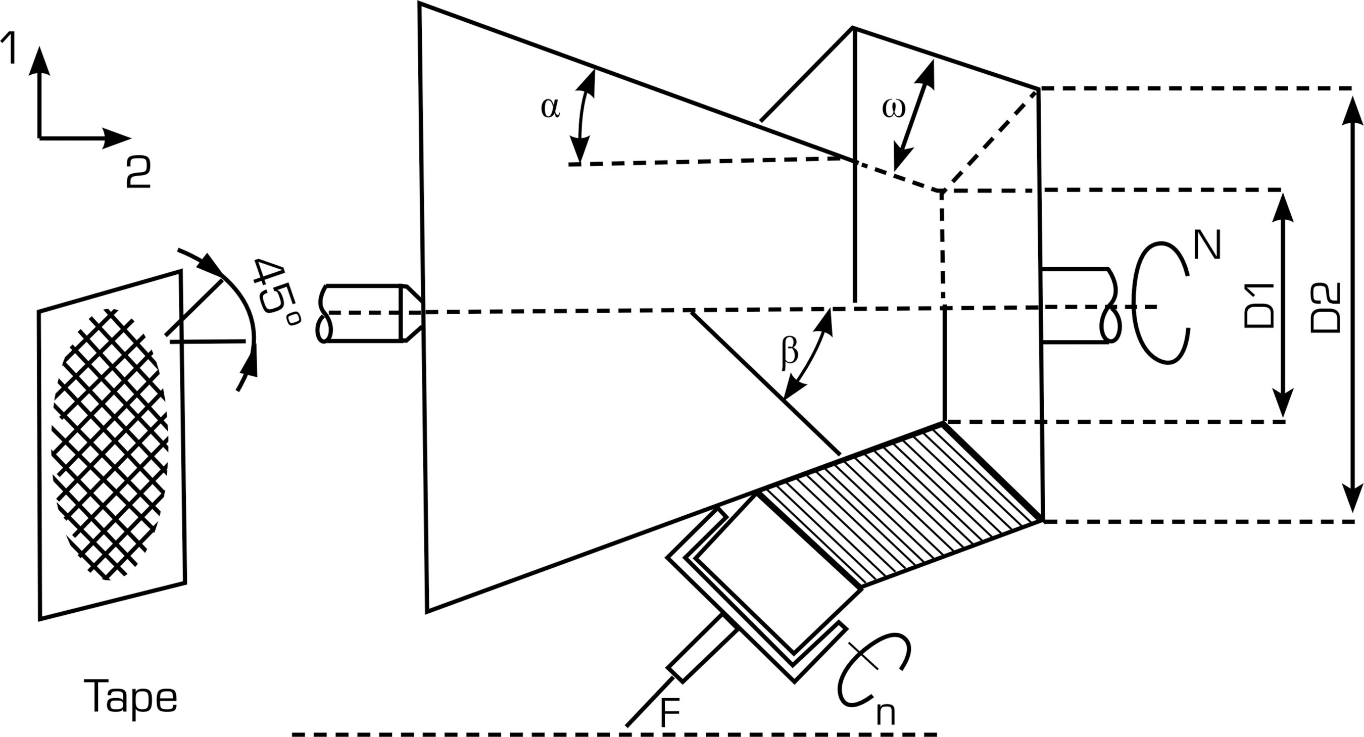
Biased wrapping on a conical mandrel. D10 = inner diameter at initial position; D20 = outer diameter at initial position; Β = angle between tape and mandrel axis; Ω = tape width.
RESULTS
Mesh convergence and edge effects
Mesh convergence is a critical step in the FEA of heterogeneous materials such as fiber-resin composites. The accuracy of the numerical solution depends on adequate mesh refinement, especially near the fiber-matrix interface, where stress concentrations and load transfer occur (Bathe 1996; Zienkiewicz and Taylor 2000). By solving the same model with progressively finer meshes, convergence is verified when successive results show negligible variation (Cook et al. 2002). This indicates that the numerical approximation approaches the true physical behavior of the composite system. Local mesh refinement in interfacial regions is often required due to high strain gradients (Reddy 1989). Proper convergence analysis also optimizes computational cost, balancing accuracy and efficiency. Thus, verifying mesh convergence is essential for validating finite element models of composites, ensuring reliable predictions of their mechanical and thermal performance (Zhang et al. 2021).
A mesh-convergence study was conducted for the models employed in the thermal and structural analyses. The outcomes obtained using five distinct mesh configurations for both the thermal and structural models with a fiber orientation of 45° are presented in Tables 4 and 5, respectively. In the thermal analyses, the convergence criterion was the temperature of the upper metal plate; in the structural analyses, it was the vertical displacement of the upper metal plate. As shown, all five mesh configurations produced satisfactory results in both cases. Nonetheless, mesh 3 was selected owing to its status as the least refined mesh that still resolves the two constituent phases (fiber and resin) adequately. This selection achieved a favorable balance between accuracy and computational efficiency.
In defining the dimensions of the finite element models used in the thermal analyses, special attention was given to minimizing edge effects on the composite specimen. The model was designed to achieve an appropriate length-to-width ratio (L/B), ensuring that the temperature distribution at the sample’s center remained unaffected by boundary influences. To establish the optimal geometry, a series of simulations was conducted by varying the L/B ratio of the representative finite element model. As summarized in Table 6, for all fiber orientation angles investigated, the temperature at the upper surface converged to a stable value, resulting in a consistent ETC. For L/B ratios equal to or greater than 4, no significant variations were observed. Consequently, the model with L/B = 4.0 was selected for the subsequent thermal analyses.
Results for the heat conduction in the permanent state analysis
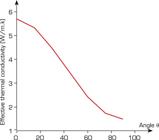
The temperature values for all thermal analyses performed with the seven finite element models are shown in Table 7. The ETC of the composite material sample was calculated using Eq.5 and appears in the last column of Table 7. The values of ETC for ϴ = 0o and 90 ° were validated through a direct comparison with analytical results, resulting in a difference below 0.1%. Figure 5 presents the temperature distribution for ϴ = 450 and heat flux = 100 kW/m2. The effect of the angle in fiber distribution is easily observed, resulting in an asymmetric distribution within the domain. Figure 6shows the ETC of the composite material sample versus angle ϴ. This curve was fitted by a fifth-degree polynomial and used to generate the values of ETC for any fiber slope.
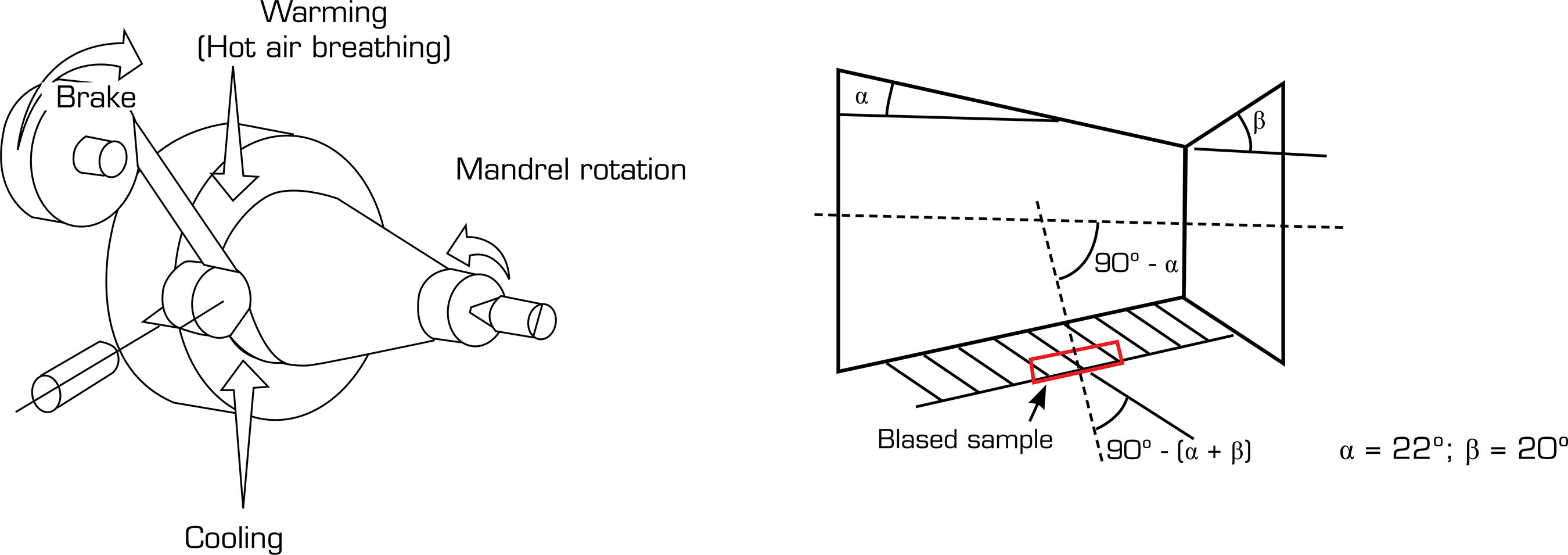
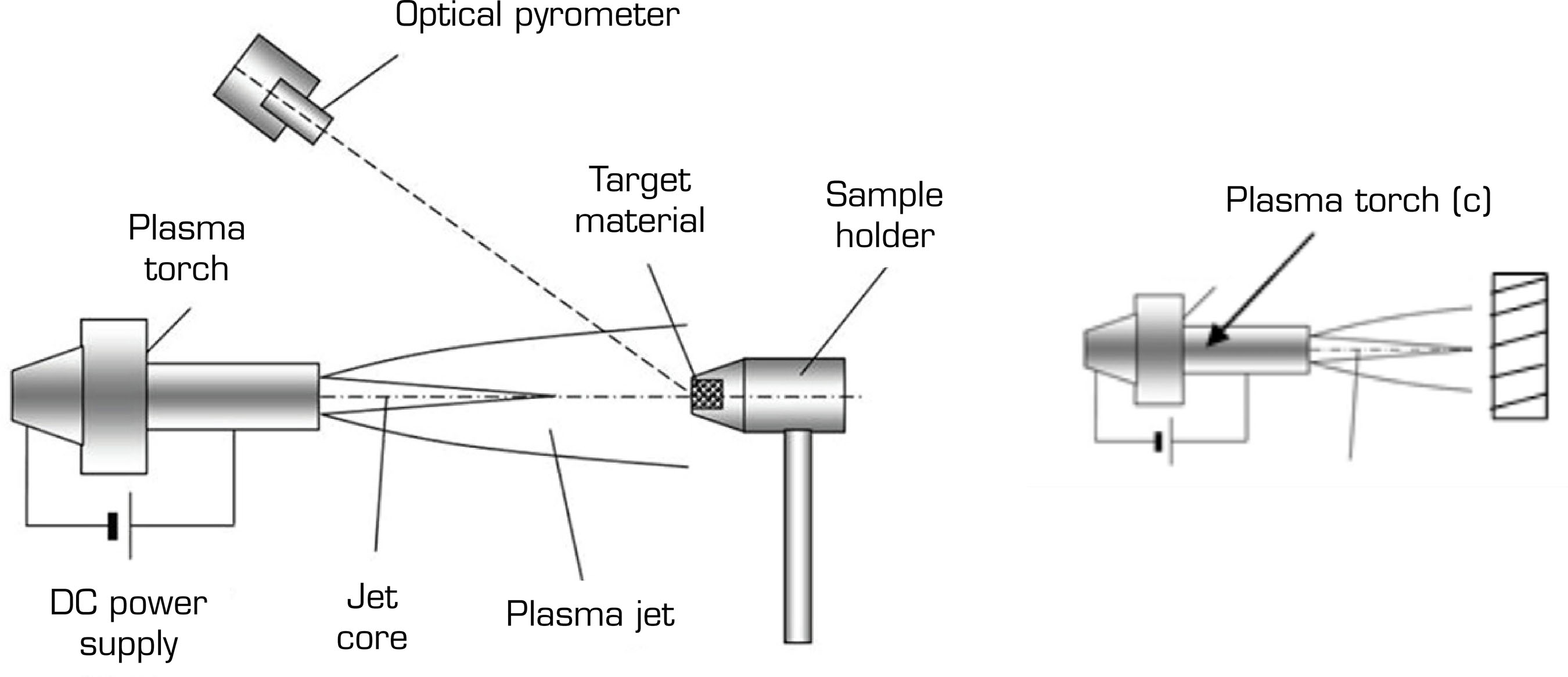
Results generated by the fitted curve for ETC (ϴ) were applied to the case of ablation in cylindrical samples submitted to a plasma jet, where the value of the thermal conductivity of the virgin material plays an important role in temperature results. The experimental results were extracted from the work of Silva et al. (2015) and compared to the values obtained with the average value of thermal conductivity used for simulation in that work. The samples were extracted from nozzles manufactured through biased wrapping, presented in Fig. 7, which permits the variation of the relative angle of inclination of fibers. The sample extraction is presented in Fig. 8, and the performed experiment is presented in Fig. 9.

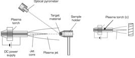
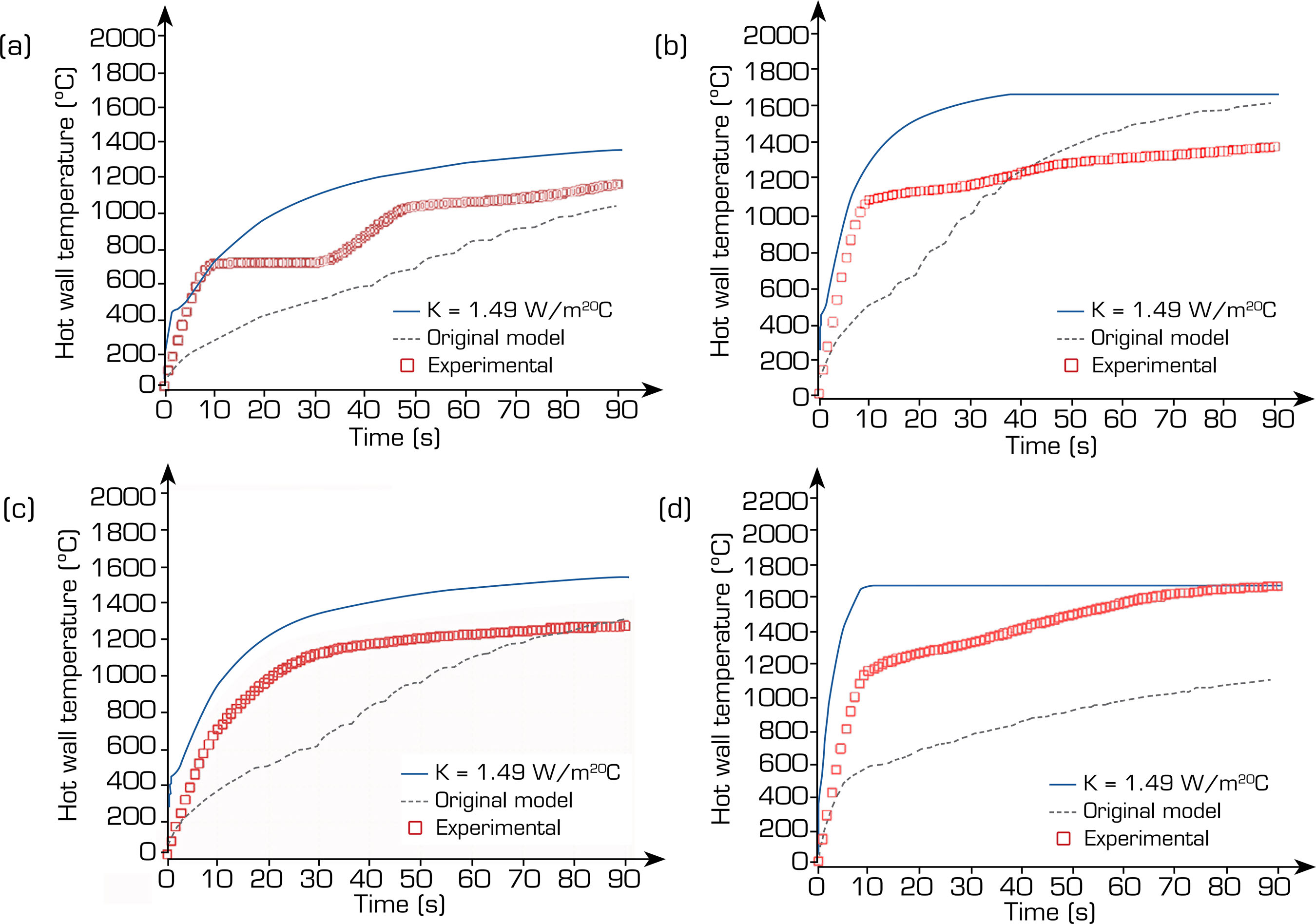
The computational procedure was the same for that reference and the current work and was described in detail in the work of Pesci (2021).The previous results from the simulation (Pesci 2021) used a thermal conductivity (K) = 0.867 W/m·°C, which resulted in the so-called “original model” curves. Figures10 and 11 present the data for temperature measured on the opposite face of this ample exposed to the plasma arc jet in a face, compared to results from numerical simulation, performed with the value of K extracted from literature and the values of ETC obtained from the fitted curve.
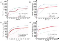
Temperature (oC) on the opposite face to the plasma jet imposed on the sample with time (s), for ϴ = 90o. (a) Q = 0.464 W·m2; (b) Q = 0.903 W·m2; (c) Q = 0.626 W·m2; (d) Q = 1.372 W·m2.

Temperature (oC) on the opposite face to the plasma jet imposed on the sample with time (s), for ϴ = 22o. (a) Q = 0.626 W·m2; (b) Q = 0.903 W·m2; (c) Q = 1.373 W·m2; (d) Q = 1.725 W·m2.
Results show that, in all cases, the curve for the ETC values obtained in the current work improves the agreement between the experimental results and the numerical simulation when compared to the value used in the original model, which was chosen considering average data extracted from literature. It is remarkable that the agreement becomes even better with the increase of heat flux imposed on the sample, since the heat conduction intensity rises with this parameter. The agreement is clearest in Fig. 11c and d, where the simulation with ETC almost matches both curves for the highest heat fluxes.
Due to the rough number of points for temperature measurement, a numerical comparison to evaluate accuracy quantitatively is better represented by the average mass loss rate, which is obtained through the formula:
The value of ṁ is estimated at five time periods of exposition tej (10 s, 30 s, 50 s, 70 s, and 90 s) for each heat flux. The sample mass was weighed before and after the time of exposition to evaluate its variation Dm. Table 8 compares the root mean square(RMS)error for the two inclinations, obtained through numerical simulation using the conductivity of the original model and the values obtained in this work (ETC). The overall RMS for the two cases, ϴ = 90o and ϴ = 22o, presented reductions of 12.38% and 15.38%, respectively, which attests to the improvement in the property value through the approach.
RMS for the original model (O.M.) and for the estimated ETC when compared to experimental results of ablation tests for the specific mass loss rate.
Results for the heat conduction in the transient state analysis
The temperature variation curves over time at points along the thickness of all seven composite samples, analyzed with the transient thermal analyses, are shown in Fig.12a-f. In these figures, position 0.00 corresponds to the point located at the interface between the lower metal plate and the composite specimen, and position 0.01 corresponds to the point located at the interface between the upper metal plate and the composite specimen, with a prescribed heat flux of 200 kW/m2 at the upper plate and a prescribed temperature of 100oC at the lower plate. Each of the seven figures corresponds to a fiber inclination (ϴ) in the range of 0º to 90º, with a variation of 15º. Points can be observed in the figures where the temperature derivative in relation to the position of the point along the thickness is not continuous. This occurs due to the sudden variation in the thermal properties of the materials (resin and fiber) that form the sample interfaces. This effect becomes clearer as the angle between the direction of heat flow and the interface of materials (resin and fiber) approaches 90. It can be seen in the figure that there are 19 points where this discontinuity occurs, corresponding to the number of interfaces existing in this model (ϴ = 90°) along the thickness.

Temperature variation curves over time at points along the thickness. (a) ϴ = 0o; (b) ϴ = 15o; (c) ϴ = 30o; (d) ϴ = 45o; (e) ϴ = 60o; (f) ϴ = 90o.
Using the results of temperature variation over time at the points of the trajectory, located along the thickness of the sample, the ETC previously obtained, and an inverse analysis technique based on Bayesian inference, the curves of the ESH mean were obtained for the seven values of the fiber inclination. Table 9shows the converged values of the ESH mean obtained, the standard deviation, and the ETC previously obtained that were used in this study. Figure 13also shows a curve (line) fitted with these values that represents the variation of the ESH as a function of the inclination of the fiber (ϴ). The fitted curve relating the ESH to the fiber inclination is shown below:
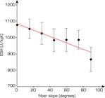
where ESH is the ESH at constant pressure and ϴis the fiber inclination in degrees.
Results for the structural static analysis
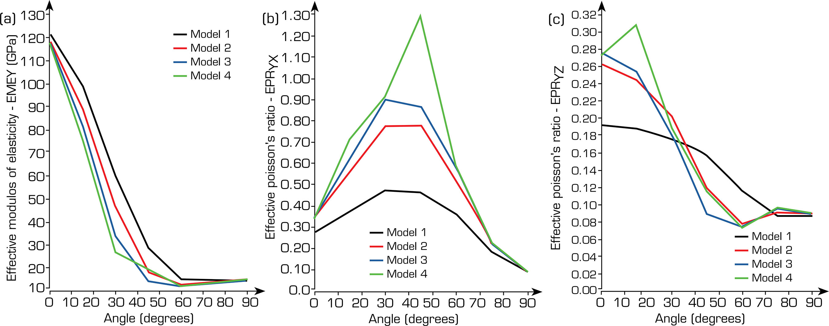
The values of the maximum variation of displacements in the four models in the three directions x, y, and z are shown in Tables 10-13. With these values, the effective modulus of elasticity (EME)in the y direction, the effective Poisson’s ratio (EPR) in the yx plane, and the EPR in the yz plan ewere calculated, which are also shown in Tables 10-13:
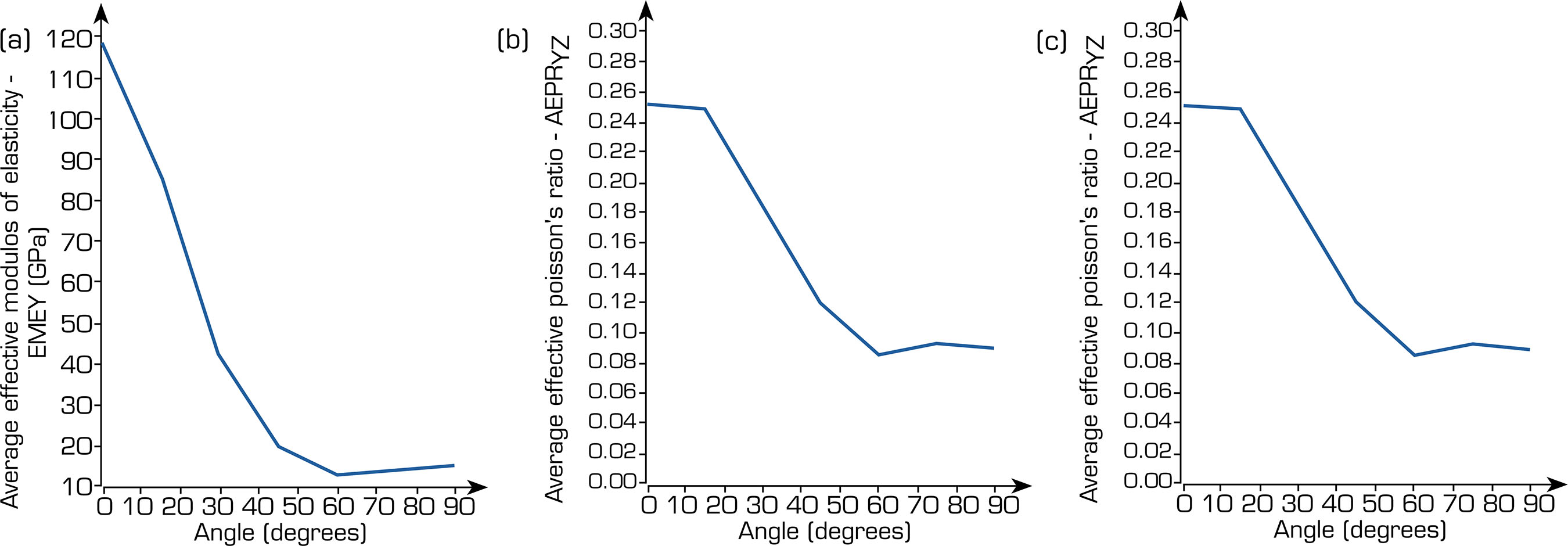
Table 14 shows the average values for the EME in the y direction, the EPR in the yx plane, and the EPR in the yz plane:
In Tables 10-14, the values shown are defined by∆LY, maximum variation of displacements in the y direction, ∆LX, maximum variation of displacements in the x direction, ∆LZ, maximum variation of displacements in the z direction, EMEY, EME in the y direction, EPRYX, EPR in the yx plane, EPRYZ, EPR in the yz plane, AEMEY, average EME in the y direction, AEPRYX, average EPR in the yx plane, AEPRYZ, average EPR in the yz plane.
The curves representing the effective elastic modulus and the EPR for each of the four models are presented in Fig. 14. These results allow for a detailed assessment of the mechanical response of the models under different configurations and loading conditions. Furthermore, Fig. 15 depicts the average values of the elastic modulus and Poisson’s ratio obtained from the four models, providing an overall comparison of their effective mechanical behavior. This comprehensive analysis facilitates the identification of general trends and the evaluation of the consistency among the numerical results derived from the different modeling approaches.

Results for modulus of elasticity and Poisson’s ratioratio. (a) EMEY; (b) EPRYX; (c) EPRYZo.

Results for average modulus ofelasticity and averagePoisson’s ratio. (a) EMEY; (b) EPRYX; (c) EPRYZo.
The displacements in the direction transverse to the applied load are greatly influenced by the fiber inclination angleϴ. This can be observed in Figs. 16 and 17, which show the displacements in the x direction for model 4, when the fiber inclination angle ϴ = 0° and ϴ = 90º.


The article by Mohamed and Abdelbary (2023) provides a detailed investigation into the relationship between fiber orientation and stiffness properties in unidirectional carbon fiber/epoxy composites. The study combines theoretical modeling and experimental testing to determine how fiber orientation affects the elastic modulus and tensile strength. Specimens with orientations of 0°, 15°, 30°, 45°, 60°, 75°, and 90° were prepared and subjected to uniaxial tensile tests. The results revealed that the elastic modulus reaches its maximum at 0°, where fibers are aligned with the loading direction, and decreases sharply as the angle increases, reaching its minimum near 90°, where the load acts transversely to the fibers. The study concludes that even small deviations in fiber orientation can cause significant reductions in overall stiffness, emphasizing the need for precise control during composite manufacturing. These findings highlight the critical role of directional modeling and fiber alignment in the structural design of high-performance composite components.
Table 15 presents the modulus of elasticity values obtained experimentally by Mohamed and Abdelbary (2023) as a function of the fiber inclination angle, as well as the values obtained in the present study through the FEM, using the same values for the thermal properties of the fiber and resin (K and Cp). The corresponding curves are shown in Fig. 18, where the experimental data and the FEM-based results are compared directly. The average error for all cases was 15.3%.
Experimental and FEM-based modulus of elasticity values as a function of fiber orientation angle.

It can be observed that the numerical results reproduce the experimental trend with good agreement for most fiber orientations. The highest consistency occurs at 0°, 30°, and 45°, where the deviations are below 15%. The maximum difference, observed at 60°, reaches approximately 36%, which may be attributed to the combined effects of shear coupling and local stress redistribution not fully captured by the simplified numerical model. Overall, the correlation between the FEM and experimental results validates the numerical approach used in this study, with errors below 10% for the majority of the orientations analyzed.
CONCLUSIONS
In this work, a simple model for the estimation of thermal and structural properties of a polymeric composite was presented, which considers the slope of the fiber and its proportion relative to the resin. Initially, the model was applied in a one-dimensional heat conduction problem to simulate the wall of a solid rocket envelope, manufactured with carbon fiber and phenolic resin by a biased wrapping process. The ETC was estimated after a numerical simulation via FEM in a two-dimensional domain, by direct application of the Fourier’s law to a steady-state heat conduction problem with a known analytical solution. The numerical data for diverse values of the slope allowed obtaining a fitted curve for ETC×ϴ, presenting good agreement with the benchmark. The numerical results of the present work were compared with the experimental data for an ablation process in an arc jet torch and also with numerical data obtained using the average value of thermal conductivity extracted from literature. Results proved that the use of ETC improved the agreement, especially at high heat fluxes.
The model was applied to estimate the ESH through the solution of a one-dimensional transient heat conduction problem. The numerical data for diverse values of the slope allowed obtaining a fitted curve for ESH×ϴ. The comparison with measurements for ablation did not present remarkable improvements.
Once thermal properties were evaluated, structural properties were estimated using this approach. Four typical finite element models were used to calculate values for the EME and the EPR. Curves varying with the angle of inclinationϴ were obtained for the EME in the y direction, the EPR in the yx plane, and the EPR in the yz plane.
The results of the FEM simulations show a strong dependence between the analyzed structural properties of the composite and the fiber inclination angle. The experimental and theoretical (FEM) curves of the modulus of elasticity results showed good agreement, with an average error of 15.3%, which allows the use of the theoretical modulus of elasticity curve via FEM in future structural analyses of the composite engine components of Institute of Aeronautics and Space. Regarding Poisson’s ratios, the results obtained by FEA were not compared to the experimental results, which should be done in future work.
The preliminary results of the present study demonstrate that the simple approach presented may be used as a valuable tool to estimate thermal and structural properties of polymeric composites when the fiber orientation is known, which is a critical aspect of rocket motor envelope design. In future works, more complex fiber distributions, such as anisotropies, should be included. Future work should improve and apply the model to other physical properties, including additional thermal and mechanical properties, to increase the accuracy in dimensioning solid rocket motor envelopes made with wrapped polymeric composites.
ACKNOWLEDGEMENTS
Not applicable
DECLARATION OF USE OF ARTIFICIAL INTELLIGENCE TOOLS
FUNDING
Peer Review History:
DATA AVAILABILITY STATEMENT
All data are presented/discussed in the article.
REFERENCES
-
Andrianov IV, Danishevs KVV, Kalamkarov AL (2010) Analysis of the effective conductivity of composite materials in the entire range of volume fractions of inclusions up to the percolation threshold. Compos Part B Eng 41(6):503-507. https://doi.org/10.1016/j.compositesb.2010.05.001
» https://doi.org/10.1016/j.compositesb.2010.05.001 - Bathe KW (1996) Finite element procedures. Englewood Cliffs: Prentice Hall.
- Cook RD, Malkus DS, Plesha ME, Witt RJ (2002) Concepts and applications of finite element analysis. 4th ed. New York: John Wiley & Sons.
-
Cotta CPN (2009) Problemas inversos de condução de calor em meios heterogêneos: analise teórico-experimental via transformação integral, inferência bayesiana e termografia por infravermelho (PhD thesis). Rio de Janeiro: COPPE/UFRJ. In Portuguese. https://w1files.solucaoatrio.net.br/atrio/ufrj-pem_upl/THESIS/1359/carolinapalmanaveiracotta1_20200512160147541.pdf
» https://w1files.solucaoatrio.net.br/atrio/ufrj-pem_upl/THESIS/1359/carolinapalmanaveiracotta1_20200512160147541.pdf -
Gou JJ, Dai YJ, Li S, Tao WQ (2015) Numerical study of effective thermal conductivities of plain woven composites by unit cells of different sizes. Int J Heat Mass Transf 91:829-840. https://doi.org/10.1016/j.ijheatmasstransfer.2015.07.074
» https://doi.org/10.1016/j.ijheatmasstransfer.2015.07.074 -
Hu J, Wu G, Zhang Q, Gou H (2014) Mechanical properties and damping capacity of SiCp/TiNif/Al composite with different volume fraction of SiC particle. Compos Part B Eng 66:400-406. https://doi.org/10.1016/j.compositesb.2014.06.013
» https://doi.org/10.1016/j.compositesb.2014.06.013 -
Jena H, Pradhan P, Purohit A (2023) Dielectric properties, thermal analysis, and conductivity studies of biodegradable and biocompatible polymer nanocomposites. In: Deshmukh K, Pandey M, editors.Biodegradable and biocompatible polymer nanocomposites: Processing, characterization, and applications Elsevier. p. 113-140. https://doi.org/10.1016/B978-0-323-91696-7.00011-8
» https://doi.org/10.1016/B978-0-323-91696-7.00011-8 -
Kai D, Kui L, Qian Z, Bohong G, Bazhong S (2016) Experimental and numerical analyses on the thermal conductive behaviors of carbon fiber/epoxy plain woven composites. Int J Heat Mass Transf 102:501-517. https://doi.org/10.1016/j.ijheatmasstransfer.2016.06.035
» https://doi.org/10.1016/j.ijheatmasstransfer.2016.06.035 -
Kursa M, Kowalczyk-Gajewska K, Petryk H (2014) Multi-objective optimization of thermo-mechanical properties of metal-ceramic composites. Compos Part B Eng 60:586-596. https://doi.org/10.1016/j.compositesb.2014.01.009
» https://doi.org/10.1016/j.compositesb.2014.01.009 -
Li H, Li S, Wang Y (2011) Prediction of effective thermal conductivities of woven fabric composites using unit cells at multiple length scales.J Mater Res 26:384-394. https://doi.org/10.1557/jmr.2010.51
» https://doi.org/10.1557/jmr.2010.51 -
Lijia Q, Xming P, Jianqiu Z, Jingxin Y, Shishun L, David H (2017) Theoretical model and finite element simulation on the effective thermal conductivity of particulate composite materials. Compos Part B Eng116:291-297. https://doi.org/10.1016/j.compositesb.2016.10.067
» https://doi.org/10.1016/j.compositesb.2016.10.067 - Machado HA (2016) Análise inversa na transferência de calor em veículos espaciais e sub-orbitais. Rio de Janeiro: CNPq.
-
Miranda G, Buciumeanu M, Carvalho O, Soares D, Silva FS (2015) Interface analysis and wear behavior of Ni particulate reinforced aluminum-silicon composites produced by PM. Compos Part B Eng 69:101-110. https://doi.org/10.1016/j.compositesb.2014.09.017
» https://doi.org/10.1016/j.compositesb.2014.09.017 -
Mohamed Y, Abdelbary A (2023) Theoretical and experimental study on the influence of fiber orientation on the tensile properties of unidirectional carbon fiber/epoxy composite.Alexandria Eng J 67(6):693-705. https://doi.org/10.1016/j.aej.2022.12.058
» https://doi.org/10.1016/j.aej.2022.12.058 -
Mosanenzadeh SG, Naguib HE (2016) Effect of filler arrangement and networking of hexagonal boron nitride on the conductivity of new thermal management polymeric composites. Compos Part B Eng 85:24-30. https://doi.org/10.1016/j.compositesb.2015.09.021
» https://doi.org/10.1016/j.compositesb.2015.09.021 - Özisik MN, Orlande HRB (2000) Inverse heat transfer. London: Taylor & Francis.
-
Pesci PGS (2021) Estudo de ablação em materiais de proteção térmica para veículos espaciais (PhD thesis).São José dos Campos: ITA. In Portuguese. https://sucupira-legado.capes.gov.br/sucupira/public/consultas/coleta/trabalhoConclusao/viewTrabalhoConclusao.jsf?popup=true&id_trabalho=11080255
» https://sucupira-legado.capes.gov.br/sucupira/public/consultas/coleta/trabalhoConclusao/viewTrabalhoConclusao.jsf?popup=true&id_trabalho=11080255 -
Pradhan P, Purohit A, Mohapatra SS, Subudhi C, Das M, Singh NK, Sahoo BB (2022) A computational investigation for the impact of particle size on the mechanical and thermal properties of teak wood dust (TWD)-filled polyester composites. Mater Today Proc 63:756-763. https://doi.org/10.1016/j.matpr.2022.05.136
» https://doi.org/10.1016/j.matpr.2022.05.136 -
Pradhan P, urohit A, Jena H, Sing J, Sahoo BB (2025) Effects of spherical fillers reinforcement on the efficacy of thermal conductivity in epoxy and polyester matrices: Experimental validation and prediction using finite element method.J Vinyl Addit Technol 31(1):109-120. https://doi.org/10.1002/vnl.22159
» https://doi.org/10.1002/vnl.22159 -
Purohit A, Pradhan P, Palanimuthu S, Kumar A, Chauhan PK (2024) A novel study on the stacking sequence and mechanical properties of jute–Kevlar–epoxy composites.J Radioanal Nucl Chem Interactions245:100. https://doi.org/10.1007/s10751-024-01946-6
» https://doi.org/10.1007/s10751-024-01946-6 -
Purohit A, Pradhan P, Palanimuthu S, Kumar A, Chauhan PK (2025) Mechanical and tribological characteristics of glass fiber and rice stubble-filled epoxy–LD sludge hybrid composites.J Elastomers Plast 57(1):113-131. https://doi.org/10.1177/00952443241305709
» https://doi.org/10.1177/00952443241305709 -
Quanjin MA, Rejab MRM, Kaige J, Idris MS, Harith MN (2018) Filament winding technique, experiment and simulation analysis on tubular structure. IOP Conf Ser Mater Sci Eng 342:012029. https://doi.org/10.1088/1757-899X/342/1/012029
» https://doi.org/10.1088/1757-899X/342/1/012029 - Reddy JN (1989) Mechanics of composite materials and structures. Dordrecht: Springer.
-
Sahoo B, Pradhan P, Purohit A, Jena H, Sahoo BB (2025) Dielectric and thermal behavior analysis of polyester composites filled with pineapple wood dust using finite element method. Int J Polym Anal Charact 30(6):666-674. https://doi.org/10.1080/1023666X.2025.2496319
» https://doi.org/10.1080/1023666X.2025.2496319 -
Sburlati R, Monetto I (2016) Effect of an inhomogeneous interphase zone on the bulk modulus of a particulate composite containing spherical inclusions.Compos Part B Eng 97:309-316. https://doi.org/10.1016/j.compositesb.2016.04.038
» https://doi.org/10.1016/j.compositesb.2016.04.038 - Schwartz MM (1984) Composite materials handbook. New York: McGraw-Hill.
-
Silva SFC, Machado HA, Bittencourt E (2015) Effect of the fiber orientation relatively to the plasma flow direction in the ablation process of a carbon-phenolic composite. J Aerosp Technol Manag7(1). https://doi.org/10.5028/jatm.v7i1.437
» https://doi.org/10.5028/jatm.v7i1.437 -
Xing J, Radovic M, Muliana A (2016) Thermal properties of BaTiO3/Ag composites at different. Compos Part B Eng 90(1). https://doi.org/10.1016/j.compositesb.2015.12.014
» https://doi.org/10.1016/j.compositesb.2015.12.014 -
Zhang Y, Liu J, Chen X (2021) Numerical modeling of fiber–matrix interfacial behavior in composite materials. Compos Sci Technol 213:108949. https://doi.org/10.1016/j.compscitech.2021.108949
» https://doi.org/10.1016/j.compscitech.2021.108949 - Zienkiewicz OC, Taylor RL (2000) The finite element method: Volume 1 – The basis. 5th ed. Oxford: Butterworth-Heinemann.

 Source: Retrieved from
  Source: Elaborated by the authors.
 Source: Elaborated by the authors.
 Source: Elaborated by the authors.
 Source: Elaborated by the authors.
 Source: Elaborated by the authors.
 Source: Retrieved from Silva (2015)
 Source: Retrieved from Silva (2015).
 Source: Retrieved from Silva (2015).
 Source: Elaborated by the authors.
 Source: Elaborated by the authors.
 Source: Elaborated by the authors.
 Source: Elaborated by the authors.
 Source: Elaborated by the authors.
 Source: Elaborated by the authors.
 Source: Elaborated by the authors.
 Source: Adapted from Mohamed and Abdelbary (2023).