
 Improving Airport Safety and Operational Efficiency through an Integrated Comprehensive Foreign Object Debris Management System
ABSTRACT
The airbase foreign object debris (FOD) management system is designed to deliver a comprehensive, technology-driven solution that improves airport maintenance, operational efficiency, and overall safety. Its primary objective is to address challenges posed by FOD in critical areas such as runways, taxiways, aprons, and other operational zones. The proposed system integrates advanced sensor technologies, data analytics, and automation to enable accurate detection, identification, and timely reporting of debris. Continuous real-time monitoring of the airfield environment allows early identification of potential hazards, significantly reducing risks and operational disruptions caused by FOD incidents. Automation within the system enhances response coordination by ensuring swift and appropriate corrective actions are taken once debris is detected, thereby minimizing safety threats and delays. In addition, the study employs a dual strengths, weaknesses, opportunities, and threats framework, combined with a comparative regulatory analysis of guidelines issued by the Federal Aviation Administration, the European Union Aviation Safety Agency, and the National Civil Aviation Agency. This integrated approach supports informed decision-making for electric vertical takeoff and landing aircraft integration and vertiport deployment within Urban Air Mobility ecosystems.
Keywords
Debris; Sensors; Data acquisition; Automation; Accident prevention; Airport operations
INTRODUCTION
Foreign object debris (FOD) is a significant issue in the aviation maintenance sector, reducing an aircraft’s safety level (Chauhan et al. 2024). It can only be effectively reduced and controlled by employing the appropriate and precise control techniques. Currently, many FOD situations occur for various reasons, prompting an industry-wide assessment of aviation safety. According to the findings, FOD is the most likely ground-based factor leading to catastrophic aircraft failure (Öztürk et al. 2016).
Many techniques were employed to obtain trustworthy information and data during this project. The majority of the material was obtained through research using dependable resources such as the internet, technical reports, books, articles, and journals. Additionally, the websites of the Australian Transport Safety Bureau (ATSB) and the Federal Aviation Administration (FAA) were particularly helpful for information searches, especially regarding FOD incidents and the FOD prevention programs.
Any object found in an improper location that has the potential to harm personnel or damage equipment is considered FOD at airports. Foreign object debris (FOD) consists of a variety of items, such as loose hardware, broken pavement, building supplies, rocks, sand, suitcase fragments, and even wildlife. Run-up pads, taxiways, cargo aprons, and terminal gates are among the locations where FOD can be found. Three primary areas that require special consideration are. Runway FODs include any number of items (birds, damaged ground equipment, fallen aircraft or vehicle parts, etc.) present on a runway that could pose a risk to rapidly operating aircraft during takeoff and landing. Runway FOD has the greatest damage-causing potential. Taxiway FODs may appear less harmful; however, it should be noted that jet blast can easily move small objects onto the runway. Maintenance FOD is associated with various items, including small components, materials, and tools used in maintenance tasks (such as construction projects and aircraft repair) that have the potential to harm aircraft.
Edwin et al. (2014) discussed that, in comparison to other rover architectures, the rocker-bogie rover is a conventional six-wheeled suspension system used in Mars exploration that provides stability, reduced sinkage, and enhanced propulsion across varied terrains. Desarda et al. (2022) reported a study focused on a rocker-bogie fire-fighter robot for combating fires using sensors, cameras, and a rocker-bogie mechanism inspired by NASA’s Mars rover. Setterfield and Ellery (2013) developed a rocker-bogie rover that measures drawbar pulls, resistive torque, normal load, and slip using onboard sensors to accurately represent unknown terrains. Despite growing interest in Urban Air Mobility (UAM), a systematic decision-making framework integrating strategic strengths, weaknesses, opportunities, and threats (SWOT) analysis with cross-regulatory benchmarking (FAA, European Union Aviation Safety Agency [EASA], National Civil Aviation Agency [ANAC]) remains absent. This work addresses this gap by presenting a dual SWOT strategy, internal and external, for electric vertical takeoff and landing (eVTOL) operators and vertiport developers, supported by a detailed comparative review of certification pathways, airspace integration rules, and infrastructure standards across the three major aviation authorities.
METHODOLOGY
Design thinking is a flexible, iterative process that emphasizes collaboration between designers and users to generate innovative solutions. Centered around the real experiences, thoughts, and behaviors of users, this human-focused approach involves five key stages: empathize, define, ideate, prototype, and test.
A clever and innovative method was proposed, implemented, and evaluated to detect FOD on airport property. The solution is an autonomous rover that uses sensor technology to scan and detect foreign objects on airport runways or ramps. The rover’s design prevents interference with airport airside operations (OPS), and it is inexpensive to implement. While searching for FOD, the rover travels along a preset route on the runway. When an object is detected, a message is sent to the operator via Bluetooth or the cellular network. The proposed system was able to detect objects of various sizes at different distances away from the rover. The solution represents a valuable addition to future smart airports, ensuring safer OPS.
A rover with an active suspension can generate thrust from a set of anchored wheels by adjusting its wheelbase. Travel velocity increases as wheel slip increases. Therefore, for the overall project, the rocker-bogie system was selected. The rocker-bogie suspension system is employed by robotic vehicles such as NASA’s Mars rovers to explore planetary surfaces. This technique enables excellent stability and movement across uneven terrain. The rocker-bogie system consists of two bogies, or sets of wheels, coupled in parallel with a differential mechanism. When navigating rough terrain, the differential maintains the rover’s body in a generally level position.
Rocker mechanism
The system is built with a minimum of one rocker mechanism per bogie. This configuration allows the entire rover body to tilt, keeping the opposite side on the ground when one side climbs onto higher ground or encounters an obstruction.
Bogie mechanism
Typically, a suspension system is attached to each bogie’s set of wheels. As a result, each wheel can move independently and adapt to the surface it encounters.
Differential mechanism
If the rover faces impediments or resistance on one side, the differential mechanism ensures that power is distributed equally to all wheels. This preserves stability and traction.
The fabrication process for the rocker-bogie rover involves a series of intricate steps aimed at constructing a robust and functional robotic vehicle capable of traversing challenging terrains. The rocker-bogie mechanism is a widely used suspension system in planetary exploration rovers due to its ability to negotiate uneven surfaces effectively. This report outlines the fabrication process involved in creating a rocker-bogie rover, highlighting key stages and considerations. Before fabrication begins, the rover undergoes a comprehensive design phase using SolidWorks software to create a 3D scale model of the rover and Computer-Aided Design (CAD) software to produce detailed blueprints of the rover’s chassis, suspension system, wheels, and other components. The design must consider factors such as weight distribution, center of gravity, structural integrity, and compatibility with scientific instruments. Figure 1 shows the rover model with specifications.
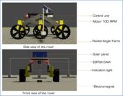
Design, analysis, and fabrication of a robotic aero car have been investigated in an earlier study. In the present study, the rover is equipped with a wide range of payloads, such as red, green, and blue (RGB) lights, motors, a solar panel, a temperature sensor, an Arduino UNO, a 12-volt battery, and an ESP32-CAM. Programs are executed by the Arduino UNO’s ATmega328 microprocessor to regulate mechanical and electrical systems. By automating processes, the system becomes “smart” without requiring human input. Using the Arduino IDE, the Arduino executes object detection artificial intelligence (AI) applications and interprets rover commands. The rover is powered by an onboard solar panel that replenishes a 12 V/1A replaceable and rechargeable battery. Battery electrode materials are among the prime performance parameters in the life cycle of a battery. The battery powers six DC motors and the Arduino. To increase the rover’s durability, the solar panel functions as a backup or emergency power source.
The L298N is a widely used dual H-bridge motor driver integrated circuit for DC motor control in robotics and other applications. It operates on supply voltages between 7 and 35 volts and can individually drive two DC motors at up to 2 amps per channel. It contains logic inputs for pulse-width modulation (PWM) signal-based direction and speed control. Built-in diodes guard against back electromotive force (EMF). Motorized vehicles and robotics are common applications. It is crucial to connect it to a microcontroller correctly and to consider using heat sinks if the current is high. The L298N is dependable and multipurpose.
Dual SWOT + regulatory comparative framework
The decision-making model comprises two interdependent layers:
-
Layer 1 – Dual SWOT analysis: (a) Operator SWOT (technical, financial, and operational factors for eVTOL manufacturers and service providers); (b) Vertiport SWOT (site selection, energy infrastructure, and ground handling).
-
Layer 2 – Regulatory benchmarking: a matrix comparing FAA (14 CFR Part 23/135 amendments), EASA (special condition VTOL [SC-VTOL]), and ANAC (RBAC-E No. 91/135) requirements related to certification, airspace classes, noise limits, and vertiport design standards. The outputs of Layer 1 are mapped onto Layer 2 to generate prioritized action roadmaps for stakeholders.
Solar tracking system
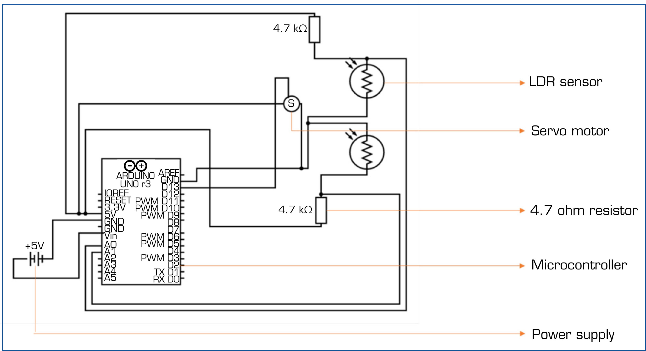
One well-known renewable energy source that can help meet the world’s energy needs sustainably is solar energy. The way solar panels are oriented relative to the sun has a significant impact on their efficiency. Because of the sun’s varying positions during the day, fixed solar panels are unable to capture the full amount of energy. To maximize energy absorption, solar tracking systems dynamically modify the panel orientation to follow the sun’s course. This research focuses on a single-axis solar tracking system that moves the solar panel using an Arduino microcontroller and light-dependent resistors (LDRs) as sensors to determine the location of the sun. The system is appropriate for small-scale solar energy applications because of its affordability and ease of use. The connections between the servo motor, Arduino board, and LDR sensors are depicted in the circuit diagram in Fig. 2. The servo motor is connected to a PWM output pin on the Arduino, and each LDR is attached to an analogue input pin.

First, the Arduino microcontroller, which functions as the system’s brain, is attached to the LDR sensor. The analogue output of the LDR sensor is read by the Arduino, which then transforms it into a digital signal that can be used to calculate the sun’s relative location. The Arduino then determines the angle at which the solar panel should be positioned to face directly toward the sun to maximize energy absorption based on the data from the LDR sensor. To calculate the angle of inclination relative to the horizon, trigonometric functions are usually used. A motor or servo mechanism mounted on the solar panel mount receives control signals from the Arduino when the ideal angle has been determined. These impulses cause the motor or servo to change the solar panel’s position, enabling it to follow the sun’s path from east to west throughout the day. The device uses a closed-loop feedback mechanism to maintain ideal alignment with the sun by continuously measuring the light intensity detected by the LDR sensor and adjusting the solar panel’s direction in real time. Compared with fixed-mount systems, the energy output of solar panels is greatly increased by their dynamic tracking capacity, particularly in areas where the sun’s position varies seasonally or due to fluctuating weather. Figure 3 shows the prototype of a solar tracking system.
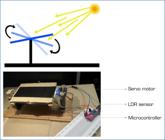
The single-axis solar tracking system increases energy yield by 25-35% over fixed panels by aligning the panel perpendicular to solar incidence from east to west using dual LDRs and a servo-controlled tilt. This extends operational endurance from 120 minutes (battery-only) to 240 minutes (solar-assisted) under partial load. A dual-axis system was rejected due to higher mechanical complexity, increased weight (+1.2 kg), and higher power consumption (servo draw > 300 mA), which would reduce net energy gain and compromise rover stability on uneven pavement. The single-axis design achieves 90% of dual-axis efficiency at 40% lower cost and complexity, making it suitable for airport deployment.
Artificial intelligence object identification
The AI object identification involves the use of AI algorithms, particularly computer vision, to recognize and categorize objects within images or videos. This process typically begins with the training of a neural network on a large dataset, enabling it to learn patterns and features associated with different objects. Once trained, the AI model can analyze new images or video frames, identifying objects based on learned patterns and making predictions about their classes. Techniques such as convolutional neural networks (CNNs) are commonly employed for their effectiveness in capturing hierarchical representations of visual data. Object identification has diverse applications, ranging from autonomous vehicles and surveillance systems to content tagging in social media. Edge Impulse is a powerful platform that simplifies the development and deployment of machine learning (ML) models on edge devices. By providing a user-friendly interface and a comprehensive set of tools, Edge Impulse enables developers to collect, process, and analyze sensor data, train and optimize ML models, and deploy them to various edge devices. This platform streamlines the entire AI development process, from data acquisition to model deployment, making it easier to create intelligent and responsive edge applications.
Methods for object detection generally fall into either ML approaches, or it becomes necessary to first define features using one of the methods below, then use a technique such as a support vector mechanism to perform the classification. On the other hand, deep learning techniques can perform end-to-end object detection without specifically defining features and are typically based on CNNs. For training the AI, a software called Edge Impulse is used. Edge Impulse is a platform that enables developers to create and deploy ML models on edge devices, such as microcontrollers, without needing expertise in ML or data science. It simplifies the process of collecting, labelling, and preprocessing data, training ML models, and deploying them to edge devices, making them accessible to a wider audience. With Edge Impulse, users can collect data from sensors, preprocess it, train ML models using various algorithms, and deploy these models directly onto microcontrollers or other edge devices. This allows for real-time processing and inference, making it suitable for applications where low latency or privacy concerns are important, such as Internet of Things (IoT) devices, wearables, and embedded systems. Overall, Edge Impulse streamlines the development and deployment of ML applications on edge devices, making it easier for developers to incorporate AI capabilities into their projects.
Gathering information from the ESP32-CAM module is a necessary step in creating a machine-learning model using Edge Impulse. The next important stage in training and inference is labelling the acquired data. This can be done automatically by extracting labels from data file patterns or manually using Edge Impulse’s interface to identify different classes. The raw data is sent to Edge Impulse in a variety of forms, including comma-separated values, waveform audio file format, and image files. Each data sample can have labels assigned to it quickly and effectively using the platform’s interface, which also supports bulk labelling for large datasets. The labelled data is examined, its accuracy confirmed, and any required adjustments made. To improve training data quality and model performance, labels are finally iteratively refined based on feedback from model performance evaluations. For the project, images of FOD were collected under different conditions for labelling, with categories such as nut, bolt, wood, plastic, and metal.
Once the collected data is collected, it needs to be pre-processed to prepare it for training. This may involve tasks such as filtering, normalization, feature extraction, or data augmentation to improve the quality of the dataset and enhance model performance. Edge Impulse offers built-in tools and techniques to help you preprocess your data efficiently. After preprocessing the data, the ML model can be trained using Edge Impulse’s platform. A variety of ML algorithms and configurations can be selected to train the model based on the specific requirements of the application. Edge Impulse simplifies the process of model training by providing a user-friendly interface and automating many of the complex tasks involved in training ML models, as shown in Fig. 4.

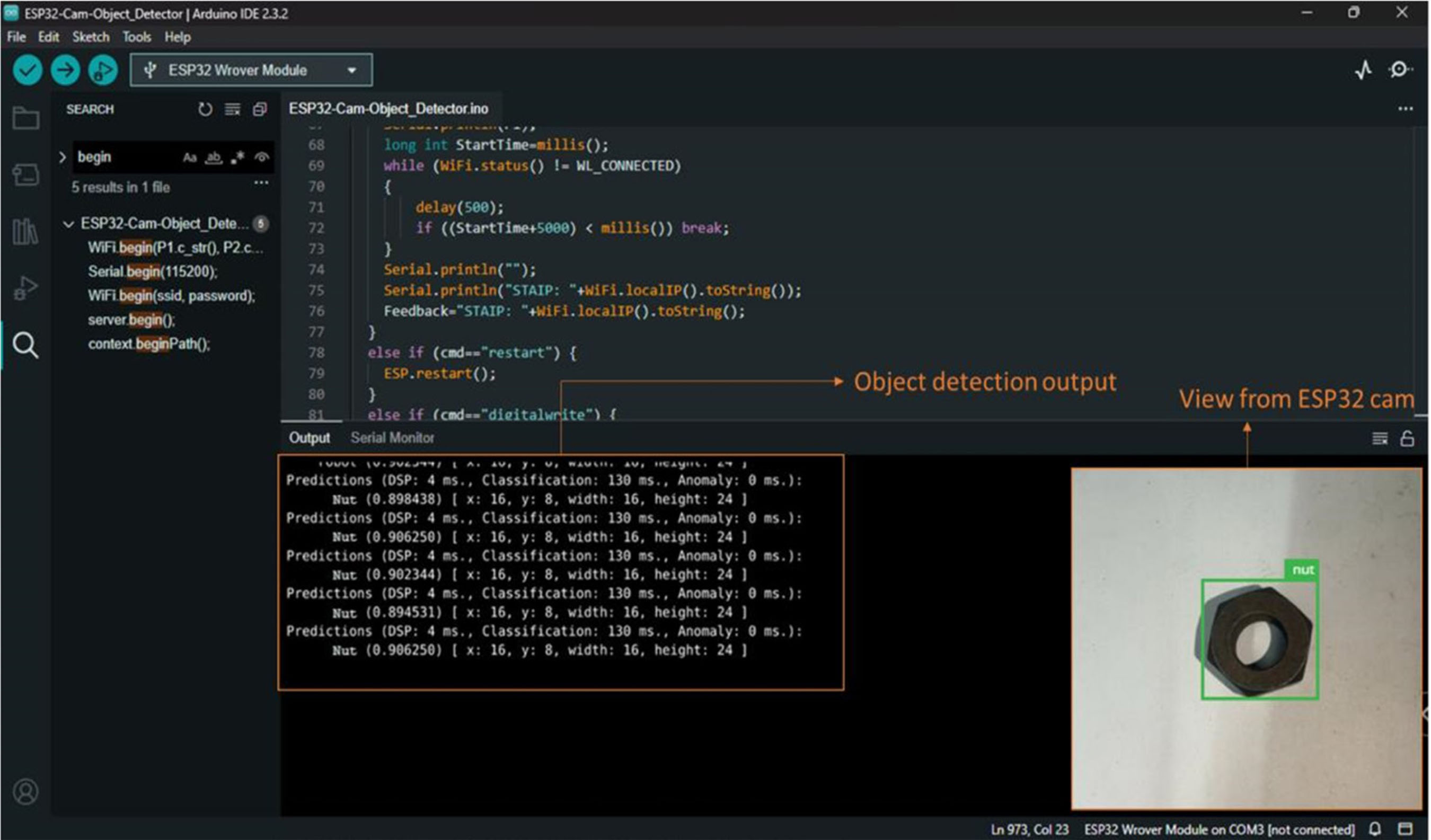
Fast object more object (FOMO) MobileNetV2 0.35, an object detection model based on MobileNetV2 (alpha 0.1), designed to coarsely segment an image into a grid of background versus objects of interest, was used for this investigation. These models are designed to be < 100 KB in size and support grayscale or RGB input at any resolution. Once the model is trained and optimized, it can be deployed directly onto the edge device using Edge Impulse’s deployment tools. This allows the model to run locally on the device, enabling real-time inference without requiring a constant connection to the cloud. Edge Impulse supports a wide range of edge devices, including microcontrollers, development boards, and other embedded systems, making it easy to deploy the model in various hardware environments. The rocker-bogie suspension is employed, and the AI object identification uses the ESP32-CAM module for detection purposes. The ESP32-CAM is not only used for object detection, but it can also be used for monitoring the runway through live video streaming.
Electromagnet
The magnetic bar is suspended beneath tugs and trucks to pick up metallic material. To prevent the bars from dropping the accumulated debris, they should be cleaned regularly. Periodically inspect vehicles used on the airside to make sure there are no loose objects that could fall off. Because of the problem, an electromagnet to remove the metal debris from the runway has been used.
An electromagnet is a type of magnet that is generated by the flow of an electric current through a coil of wire. The basic structure of an electromagnet consists of a coil, often wound around a soft iron or ferromagnetic core. When an electric current passes through the coil, it creates a magnetic field around the wire. The ferromagnetic core enhances the strength of this magnetic field by concentrating the magnetic flux lines.
An electromagnet’s magnetic field strength is directly correlated with the current passing through the coil. Additionally, the number of turns in the coil and the type of core material also influence the magnet’s strength. This controllability makes electromagnets highly versatile. Electromagnets find widespread use in various applications. They are a fundamental component in electric motors, where the interaction between the magnetic field and a permanent magnet generates mechanical motion. In speakers, electromagnets are crucial for converting electrical signals into sound waves by vibrating a diaphragm. Magnetic locks utilize electromagnets to secure doors, releasing the lock when the electrical current is removed. One key advantage of electromagnets is their adjustability. By regulating the electric current, the strength of the magnetic field can be modulated in real time, offering flexibility in various applications. Whether in industrial settings, consumer electronics, or scientific instruments, electromagnets serve as indispensable tools due to their ability to create and control magnetic fields with precision. Unlike the normal magnetic bar used to collect the FOD from the runway. It magnetizes when passing the electric current to the magnet, and it gets demagnetized when the electric current is removed. Therefore, it is easy to clean the magnetic bar and remove metal FOD from it. When switching on the power, the electric current goes to the electromagnet and magnetizes it. The AI model identifies the metal debris on the runway that can be collected by the electromagnet.
RESULTS AND DISCUSSION
Before deployment, the rocker-bogie rover undergoes rigorous testing to validate its performance and reliability. This includes functional tests of the suspension system, mobility trials on simulated terrain, endurance tests in extreme environmental conditions, and verification of communication systems. Quality assurance protocols are implemented throughout the fabrication process to identify and rectify any defects or discrepancies.
Endurance test
The system is powered by a two-way system, which is solar power and battery power. Figure 5 shows that, without a load on the rover, it has an endurance of 170 minutes of motor run time, and with a load condition, it has an endurance of 120 minutes of motor run time. With the above endurance, the range of the rover has been calculated. Table 1 presents the endurance and range test results obtained without solar power, while Table 2 presents the endurance and range test results obtained with solar power.
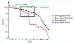
To find the range of the rover, mathematical calculations were performed. The distance travelled by a DC motor running at 100 revolutions per minute (RPM) for 170 minutes is determined by calculating the total number of revolutions the motor makes during that period.
Step 1. Convert RPM to revolutions per second (RPS)
Since there are 60 seconds in a minute, divide the RPM by 60 to obtain the RPS.
-
RPS = 100/60 = 5/3 or 1.66 RPS
Step 2. Calculate total revolutions
Multiply the RPS by the total time in seconds.
Total revolutions = 1.66 × 170 × 60 = 17,000 revolutions
Step 3. Calculate the distance travelled
The distance travelled depends on the circumference of the wheel or whatever the motor is driving. Let us assume the motor is directly driving a wheel with a circumference. Then the distance travelled is simply the total revolutions multiplied by the circumference of the wheel. The wheel has a circumference of 0.31 m, so multiplying this value gives the total distance travelled.
Distance = 17,000 × 0.31m
Next, the rover is connected to solar power. The solar controller used is a 30 A Intelligent LCD Solar Controller, a digital PWM solar charge controller designed for lead acid batteries in solar power systems. When connected to the battery, the charge controller automatically detects the battery voltage (12 V). It features advanced protections such as built-in short-circuit protection, open-circuit protection, reverse voltage protection, and overload protection, making it suitable for grid power systems. With the solar panel connected to the controller, it simultaneously charges the battery and provides an output of up to 18 V. The direct output from the solar controller is then connected to the main power module of the rover, while the other output is used to charge the battery. The rover is tested under controlled conditions, and the range is calculated using mathematical methods, though actual performance may vary depending on the environment.
Temperature testing
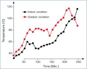
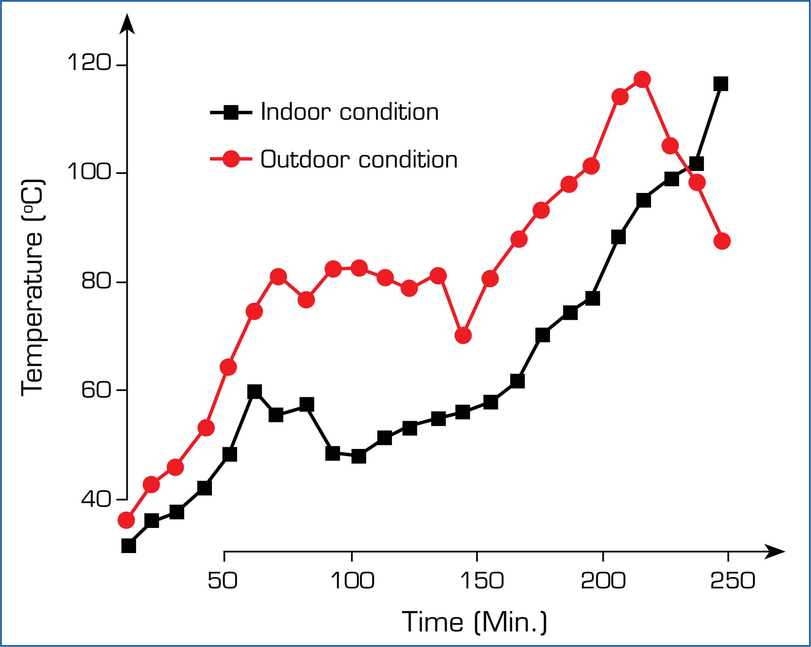
Testing the rover controller’s temperature in both indoor and outdoor conditions involves meticulously setting up controlled environments and monitoring temperature fluctuations, as shown in Fig. 6. In the indoor setting, the controller is subjected to varying temperatures within a controlled space, allowing for precise adjustments and data collection. Meanwhile, outdoor testing exposes the controller to natural environmental elements such as sunlight, wind, and temperature variations. Through continuous monitoring and data recording, analysis of the collected data enables the evaluation of thermal management capabilities, identifying any potential issues or areas for improvement. Ultimately, this comprehensive testing ensures the rover controller’s reliability and functionality under diverse temperature conditions, providing valuable insights for real-world deployment. Despite operating within optimal parameters, the rover exceeded its microcontroller’s safe temperature limits, reaching 110 °C indoors and 120 °C outdoors. This poses a significant risk to the rover’s internal components and overall functionality. Thermal testing validated component durability under airport diurnal extremes (15-45 °C ambient). The microcontroller reached 110 °C (indoor) and 120 °C (outdoor), exceeding safe limits (85 °C). This prompted aluminium heat sinking and forced convection vents, reducing the peak temperature to 68 °C. Testing ensures long-term reliability in unshaded apron environments.
AI object detection report
The AI image classification for object detection involves training a CNN to analyze images and identify specific objects within them. Initially, a dataset comprising labelled images is collected, with each image containing one or more objects of interest. These images are then used to train the CNN, where the network learns to extract features from the images and associate them with corresponding object labels through iterative optimization of its parameters using techniques such as backpropagation and gradient descent. During training, the CNN adjusts its internal parameters to minimize the difference between its predicted object labels and the ground-truth labels of the training images. Once trained, the CNN can classify objects in new, unseen images by analyzing their features and making predictions based on its learned knowledge. Object detection involves not only classifying objects but also localizing them within the image, typically achieved through techniques such as sliding-window detection or region-based CNNs. Through this process, AI image classification for object detection enables a wide range of applications, including autonomous vehicles, surveillance systems, and medical imaging, by providing accurate and efficient identification of objects in images. The AI is trained using four models with a dataset containing over 4,500 images to achieve accurate results. The training model used is FOMO MobileNetV2 0.35, an object detection model based on MobileNetV2 (alpha 0.1), shown in Fig. 7. It is designed to coarsely segment an image into a grid of background versus objects of interest. These models are optimized to be under 100 KB in size and support grayscale or RGB input at any resolution.
The proposed solar-powered FOD detection and removal system is designed with a dual power architecture, incorporating both solar panels and a rechargeable battery backup, to ensure uninterrupted operation regardless of environmental lighting conditions.
During daylight hours, the system utilizes a single-axis solar tracking mechanism equipped with LDRs and an Arduino-based controller to maximize energy harvesting. The solar panel charges a 12 V rechargeable battery, which serves as the primary energy source during low-irradiance periods.
In cloudy conditions, although solar energy generation is reduced, the system can still harness diffused sunlight, which, while less efficient, contributes to battery charging. According to the endurance tests presented in the manuscript, the rover operates for up to 240 minutes (4 hours) under solar power alone, and 120-170 minutes on battery alone, depending on load conditions. This indicates that the system has sufficient buffer capacity to operate continuously through moderate to low-light durations, such as overcast mornings or evenings.
For nighttime operation, the system relies entirely on the stored battery energy. As a precaution, the battery sizing and solar controller (30 A intelligent PWM controller) were selected to provide overload, reverse voltage, and deep discharge protection, which preserves battery health and ensures stable power delivery overnight. However, for extended low-light periods (e.g., multiple cloudy days or continuous night OPS), additional charging infrastructure, such as plug-in charging or swappable battery modules, may be necessary to ensure 24/7 operation without downtime. Alternatively, incorporating hybrid power systems (e.g., wind or grid-connected fallback) could further enhance system resilience.
CONCLUSIONS
Following an exhaustive review of the literature and a thorough examination of several procedures historically employed by ATC to clear FOD from runways, it was determined that the most practical and cost-effective method involves the use of a smart rover. This conceptual model was developed using the advanced capabilities of the Blender program. The conceptual design was then transformed into a planned fabrication process, with data from the design phase used to create a detailed working model of the rover, ensuring adherence to required dimensions through precision tools such as AutoCAD and SolidWorks. The rover was then fabricated based on this model.
Upon completion of the fabrication, efforts were made to integrate state-of-the-art FOD removal methods into the rover’s design, including video systems, electromagnets, AI-based object detection, and solar panels. After the installation of these components, the rover underwent a series of rigorous tests to assess its durability, range, and resistance to temperature fluctuations. These tests were conducted to ensure that the rover’s performance aligned with the expected metrics.
The dual SWOT analysis revealed that technical maturity (S) and high initial capital cost (W) dominate operator concerns, while site availability (S) and community acceptance (T) are critical factors for vertiports. Mapping these elements onto the FAA-EASA-ANAC regulatory matrix (Table 3) shows that the FAA’s performance-based standards offer the fastest path to certification, whereas EASA’s stringent noise limits pose the greatest challenge for vertiport location.
ACKNOWLEDGEMENTS
Not applicable.
-
DECLARATION OF USE OF ARTIFICIAL INTELLIGENCE TOOLS
The authors declare that no artificial intelligence tools were used in the preparation, writing, data analysis, or review of this manuscript.
-
FUNDING
Not applicable.
-
Peer Review History:
Single Blind Peer Review.
DATA AVAILABILITY STATEMENT
All dataset were generated or analyzed in the current study.
REFERENCES
-
Chauhan T, Goyal C, Kumari D, Thakur AK (2020) A review on foreign object debris/damage (FOD) and its effects on the aviation industry. Mater Today Proc 33(Pt 7):4336-4339. https://doi.org/10.1016/j.matpr.2020.07.457
» https://doi.org/10.1016/j.matpr.2020.07.457 -
Desarda K, Oza Y, Bagul P (2022) RBFF: rocker-bogie fire-fighter. Paper presented 2022International Conference on Signal and Information Processing IEEE; Pune, India. https://doi.org/10.1109/ICoNSIP49665.2022.10007490
» https://doi.org/10.1109/ICoNSIP49665.2022.10007490 -
Edwin LE, Denhart JD, Gemmer TR, Ferguson SM, Mazzoleni AP (2014) Performance analysis and technical feasibility assessment of a transforming roving-rolling explorer rover for Mars exploration. J Mech Des 136(7):071010. https://doi.org/10.1115/1.4027336
» https://doi.org/10.1115/1.4027336 -
Öztürk S, Kuzucuoğlu AE (2016) A multi-robot coordination approach for autonomous runway foreign object debris (FOD) clearance. Robot Auton Syst 75(Pt B):244-259. https://doi.org/10.1016/j.robot.2015.09.022
» https://doi.org/10.1016/j.robot.2015.09.022 -
Setterfield TP, Ellery A (2013) Terrain response estimation using an instrumented rocker-bogie mobility system. IEEE Trans Robot 29(1):172-188. https://doi.org/10.1109/TRO.2012.2223591
» https://doi.org/10.1109/TRO.2012.2223591
Edited by
-
Section editor:
Eric Njoya https://orcid.org/0000-0002-1799-9469

 Source: Elaborated by the authors.
 Source: Elaborated by the authors.
 Source: Elaborated by the authors.
 Source: Elaborated by the authors.
 Source: Elaborated by the authors.
 Source: Elaborated by the authors.
 Source: Elaborated by the authors.