
 Optimization of Machining Parameters to Minimize Delamination in the Drilling of Carbon Fiber/Poly(Ether Imide) Composite
ABSTRACT
Machining composites is more complex than metals due to their non-homogeneous, anisotropic nature and abrasive fibers. The machining process of composites can introduce defects, such as drilling-induced delamination, a critical factor in the rejection of drilled composite components in the aerospace industry and others. Among thermoplastic composites, poly(ether imide) (PEI) stands out for high performance, recyclability, and low cost, and is extensively employed in aerospace applications such as interior panels, structural brackets, and electrical housing. This study examines drilling parameters for carbon fiber/PEI composites to minimize delamination. In this study, four carbide tools with different point angles were tested: two with point angles of 118° and 140°, respectively, both coated with titanium nitride (TiN), one with 90° coated with diamond, and a last one with two point angles of 90° and 118°, without coating. Parameters followed manufacturer recommendations with three rotational speeds (4,000, 6,000, 8,000 rpm) and feed rates (0.025, 0.038, 0.050 mm/rev). Delamination was analyzed via high-resolution optical microscopy and ImageJ 1.54. Analysis of variance and Tukey tests identified optimal conditions. Hole entrance damage depended on rotation speed and tool geometry, with higher speeds causing more damage; the 140° point angle caused less than 118°. At the hole exit, tool type was the main factor, with the diamond tool giving the best finish. Optimal parameters were 4,000 rpm with a diamond tool.
Keywords
Composite materials; Thermoplastic resins; Carbon fiber; Machining. Drilling; Boundary layer separation
INTRODUCTION
An increasing number of applications have preferred fiber-reinforced composites over metallic materials due to their exceptional resistance to corrosion and fatigue, in addition to significant weight reduction (Jayan et al. 2021; Nixon et al. 2013). Composites can present matrices based on metals, ceramics, polymers, or carbon (Ozkan et al. 2020); however, the prevailing choice for carbon fiber (CF)-reinforced composite is a polymeric matrix, forming the CF-reinforced plastic (CFRP) materials (Mahesh et al. 2021). While thermoset matrices have traditionally dominated the industry, there has been growing interest in thermoplastic matrices due to their numerous advantages: enhanced versatility in processing techniques, increased damage tolerance, improved chemical resistance, and the potential for recycling and reusability (Elfaleh et al. 2023; Sauer and Kuhnel 2019).
Concerning structural composites, several thermoplastic matrices are commonly employed, including poly(ether ether ketone) (PEEK), poly(aryl ether ketone) (PAEK), and poly(phenylene sulphide) (PPS), all of which exhibit a semicrystalline structure, along with the amorphous poly(ether imide) (PEI) (Silva et al. 2024). PEI stands out among high-performance thermoplastic matrices due to its excellent processability and moldability, combined with superior electrical insulation and inherent flame resistance compared to PEEK and PPS. These properties allow the manufacturing of complex geometries while ensuring low smoke emission, a critical requirement for aerospace and electronic applications. Furthermore, PEI offers a favorable balance between thermal stability, dimensional accuracy, and cost-effectiveness, making it an attractive alternative for aerospace components that require compliance with stringent safety and performance requirements without incurring the high material costs associated with PEEK or PAEK (Asyraf et al. 2022; Scarselli et al. 2021; Toro et al. 2022).
According to Amancio-Filho et al. (2008), Wirth and Heath developed amorphous PEI in 1970. Its chemical structure consists of repeating units of aromatic imide, propylidene (isopropylidene), and ether groups. The aromatic imide groups confer stiffness and high thermal resistance to the polymer, while the ether groups provide PEI with good processability, associated with low melt viscosities.
In the present context, it is nearly impossible for a structural component to be fabricated without undergoing some form of machining process (Mcllhagger et al. 2020), whether it be for drilling holes or achieving the necessary surface finish as per the mechanical design requirements (Ciecieląg et al. 2021). Drilling in polymer-based composite materials is a complex process due to their non-homogeneity, anisotropy, and abrasive nature, which complicates machining and may lead to delamination and fiber pull out (Kesarwani et al. 2023; Rawal et al. 2022).
Recent studies indicate that around 60% of drilled composite parts are rejected in the aerospace industry due to damage such as drilling-induced delamination (Sharma et al. 2021). Delamination, an interlaminar crack between fiber reinforcement and polymer matrix, reduces stiffness and strength, being the most common defect in CFRP drilling (Wu et al. 2019). Figure 1a schematically illustrates the drilling forces that can cause delamination, which often limits machining tolerances and component reliability (Sharma et al. 2021; Wu et al. 2019). It can occur at both hole entry and exit (Callisaya et al. 2023; Chandrabakty et al. 2019).

Schematic of thrust force during drilling. (a) Thrust force and delamination damage during drilling; (b) Demonstration of the forces on the face of the tool; (c) Magnitude of cutting forces during drilling.
The delamination damage caused by the tool geometry has been recognized as one of the major problems during drilling (Fig. 1a) (Nayak et al. 2023). The tool characteristic influences the cutting force (force in the axial direction), characterized as a load exerted by the cutting tool on the composite, called the thrust force. Thermoplastic matrices are more prone to machining damage at lower temperatures than thermosets (Kilickap 2010; Meinhard et al. 2021).
During the drilling process, the machining temperature can easily reach approximately 180 °C. Under such conditions, the analysis of the thrust force should be conducted within a thermomechanical framework, explicitly accounting for the temperature dependence of the workpiece material properties (Biron 2007; Zhang et al. 2021). Saoudi et al. (2016, 2018) proposed a model that incorporates thermal effects during the drilling of composite materials. This model was formulated based on a thorough analysis of previously established analytical approaches by Zhang et al. (2001), while explicitly including the influence of temperature on the model parameters. According to Kubher et al. (2022), accounting for the temperature-dependent behavior of the composite material is essential for accurately predicting the thrust force and the associated damage mechanisms during machining:
where K* (T) is a temperature-dependent stress intensity factor, GIC (T) is a temperature-dependent interlaminar fracture toughness, ξ (T) is a temperature-dependent ratio of delamination dimensions, and C3, (T) is a geometric and material constant.
The applied force should not exceed the value of Eq. 1, the critical load at the onset of crack propagation, a function of the material properties, to avoid delamination (Ekici et al. 2021). Studies on acrylonitrile-butadiene-styrene and PEEK machining (Hocheng and Puw 1992; Hocheng et al. 1993) show that fracture mechanics mainly governs damage in some thermoplastics due to their high toughness. Among the drill point geometry parameters, the point angle has a major influence on the magnitude of thrust force, contributing more than 50% of the total thrust produced during drilling (Velayudham and Krishnamurthy 2007).
Figure 1b illustrates that the thrust force Fthrust consists of the force Fz1 from the chisel edge (highlighted by the red arrows), squeezing the composite material, and the force Fz2 of the main cutting edge to cut the composite material (Ge et al. 2023; Zitoune and Collombet 2007), according to Eq. 2 (Mathivanan et al. 2016; Zitoune and Collombe 2007). The chisel edge is responsible for pushing/extruding material from the center to the sides as the tool penetrates the hole. Increasing the angle enlarges the chisel edge, leading to greater material extrusion rather than cutting, which in turn raises the cutting force and, consequently, the delamination. The force generated by the chisel edge FZ 1 is about ½ of the total thrust force Fthrust (Fig. 1b). Currently, numerous studies are focused on minimizing the contact between the chisel edge and the work material, aiming to reduce the thrust force and thus the delamination factor (Mathivanan et al. 2016):
Figure 1c illustrates the curve of the thrust force in the drilling process. The curve initiates with the chisel contacting the workpiece at point O, followed by the entry of the chisel edge into the workpiece at point A, leading to a sharp increase in thrust force (O-A). Point A is designated as the location where the cutting force acts on the chisel edge, and point B breaks through the back surface of the plate. There is a significant reduction in thrust force (Mathivanan et al. 2016).
The machining process critically depends on material characteristics and cutting parameters (Singh et al. 2021). For this reason, it is of utmost importance to correctly select the mechanisms for material removal to ensure optimal cutting tool performance, excellent surface quality, and effective control of residual stresses generated during this process (Mathivanan et al. 2016; Wang et al. 2021). Defects resulting from the manufacturing process of CFRP can create areas of high-stress concentration (El Moumen et al. 2019). Prolonged usage of a specific component with such defects may lead to premature damage, even when subjected to loads below the limit specified by the manufacturer (Rubino et al. 2020).
In this context, to assess the influence of the hole on the durability of a CF/PEI component, this study aims to determine the optimal parameters for drilling CF/PEI test specimens with 6 mm holes, minimizing delamination as much as possible, to be used in a comparative fatigue study with CF/PEI without a hole according to Silva et al. (2024). The specimens will adhere to the dimensions specified in the American Society for Testing and Materials (ASTM) D7615/D7615M-23 standard: Standard Practice for Open-Hole Fatigue Response of Polymer Matrix Composite Laminates, as shown in Fig. 2.

Dimensions required for the fatigue test according to ASTM D7615/D7615M-23 (dimensions in mm).
For drilling the CF/PEI specimens, four drills with different tip angles were selected, as they are the most commonly used. Consequently, the drilling parameters – rotational speed and feed rate – were set according to the recommendations of the cutting tool manufacturers. The selected tip angles were 118°, 140°, 90°, and a fourth drill featuring a combination of 118° and 90°. The chosen rotational speeds and feed rates were 4,000, 6,000, and 8,000 rpm, with feed rates of 0.025, 0.038, and 0.050 mm/tooth.
Experimental
Materials
The laminates had a stacking sequence of ([0.90] [45])2s and dimensions of 500 mm × 500 mm, supplied by Toray Advanced Composites (Netherlands). Eight layers of T300 3K CF fabric (280 g/m²) with 42% matrix weight fraction were used, yielding a density of 1.51 g·cm³ and a thickness of 0.31 mm per layer, totaling 2.48 mm. PEI polymer has a density of 1.27 g·cm³, Tg of 217 °C, and is processed between 320-350 °C. According to Toray (Cetex TC 1000 PEI datasheet), laminate FT 300 B shows, under room temperature dry conditions, tensile strength at 90° of 495 MPa, compression strength at 90° of 481 MPa, and flexural modulus at 0° of 26.3 GPa.
Drilling test
Drilling tests were conducted to identify optimal parameters that minimize delamination in CF/PEI laminate holes. This supports specimen preparation for fatigue tests per ASTM D7615/D7615M-23 and assists industries working with thermoplastic composite drilling. For fatigue testing, specimens must follow ASTM D5766/D5766M-11, which requires a 6 mm hole.
Drilling tests were carried out on a DMG DMU 50 ECO vertical machining center; the assembly during the test specimen is shown in Fig. 3a, following the machining parameters described in Table 1. The minimum values selected were based on the tool manufacturer’s specifications, and the higher values were selected, aiming to test the effect on productivity.

Setup for drilling. (a) Experimental assembly during testing; (b) Tools used; (c) Specimen used in drilling (dimensions in mm).
The experimental design used was a full factorial, with two factors (rotation and feed rate) with three levels and one factor (tool) with four levels, totaling 36 conditions. Two repetitions were performed for each condition, totaling 72 trials.
Within the context of this study, four distinct categories of cutting tools were used, crafted from a variety of materials and featuring different geometric configurations. The detailed specifications of each tool are provided in Table 2. Figure 3b shows the four tools used. To facilitate drilling, laminate plates measuring 250 mm in length and 25 mm in width were used. Figure 3c shows the dimensions of the specimens. Each plate accommodated approximately 17 holes, with sufficient spacing between them. To mitigate the influence of vibrations, the specimens were securely clamped, and the machining was performed dry.
Quantification of delamination
According to Babu et al. (2016) and Ekici et al. (2021), the methodologies employed for evaluating delamination exhibit substantial diversity among researchers, with some relying on measurements of delaminated surface area or crack length, while others prefer quantification through ratios of delaminated surface areas or radii in comparison to reference areas or radii. Currently, three primary measurement methods are widely used in the literature to evaluate delamination caused during the drilling process: one-dimensional, two-dimensional, and three-dimensional techniques.
According to Geng et al. (2019) and Kumar et al. (2022), various image acquisition techniques are used for non-destructive measurements, with the most common being optical microscopy, digital photography, ultrasonic C-scan, and X-ray. Visual measurements performed using optical microscopes, scanning electron microscopes, digital cameras, and scanners are practical and cost-effective methods widely adopted by researchers. Image processing – including enhancement and analysis – plays a crucial role in ensuring measurement accuracy. However, accurately measuring delamination using visualization techniques remains difficult for dark composites such as CFRP. Furthermore, these techniques face significant limitations in detecting hidden delamination within the composite laminates.
In this study, the two-dimensional method was chosen to evaluate the delamination due to its widespread use and the possibility of performing measurements with a microscope that offers high-quality images (Ge et al. 2023; Yu et al. 2023). This approach considers the hole area, nominal area, and delaminated area. The nominal area represents the ideal area, that is, if the hole precisely matches the drill size. In our research, the nominal area corresponds to the area for a diameter of 6 mm. For this, images of the entry and exit damage areas of the drilled holes were obtained using an Olympus DSX500 digital microscope. The image presented in Fig. 4 was captured at approximately 50× magnification, with a scale bar of 500 µm and an image resolution of 2,560 × 1,920 pixels to determine the extent of delamination produced by drilling, according to Eq. 3 (Babu et al. 2016; Ekici et al. 2022):

Procedures for ascertaining the dimensions of the delaminated hole. (a) Digital image; (b) Binary image; (c) Perimeter of the damaged hole Adel.
This equation considers the ratio of the delaminated area (Adel) to the nominal hole area (Anom), as shown in the literature (Babu et al. 2016; Ekici et al. 2022).
Figure 4 illustrates the process for determining the extent of damage. The image was processed using ImageJ 1.54, a public domain software provided by the National Institutes of Health in the United States. To attain an image of satisfactory quality, it is crucial to carefully choose a specific set of parameters, which includes brightness intensity, image enhancement, and edge detection. Following the adjustment of these settings, the image was converted to 8-bit and binarized using the default thresholding method. The scale was calibrated based on the 1 mm reference bar, and measurements were performed in millimeters. The “analyze measure” function was applied to determine the perimeter length of the circle, which was then converted into the corresponding area expressed in mm².
RESULTS AND DISCUSSION
Drilling experiments were conducted to evaluate the effects of cutting parameters and tool types on hole damage, especially at the entry and exit points. Figure 5 shows representative images of the specimens with the drilled holes, considering the entry and exit points, for the four tools tested, obtained with a revolution of 4,000 rpm and a feed rate of 0.025 mm/rev. Measurement repeatability was assessed to ensure the reliability of the delamination factor (Fd) calculation. Each hole was analyzed twice using the same image processing procedure. The resulting area deviation for each tool was as follows: T1 ± 0.93 mm², T2 ± 0.25 mm², T3 ± 0.29 mm², and T4 ± 0.60 mm². Other holes were obtained using the full factorial configurations 23 and the parameters depicted in Table 1 for all selected tools. The extent of damage in the vicinity of these regions was accurately quantified, and the delamination factor was determined using Eq. 3. To comprehensively analyze the impact of the N and f parameters (Table 1) and the tool variations on the hole delamination, analysis of variance (ANOVA) and Tukey’s test were used, both performed with a 95% confidence level.

Representative images of the drilled holes, entry and exit points, obtained with the four tools at 4,000 rpm and feed 0.025 mm/rev. (a) T1; (b) T2; (c) T3; (d) T4.
Figure 6 shows the main effect plot of cutting parameters on the means of delamination at the workpiece entrance. As the rotation increased, delamination also increased, with T3 (diamond tool) proving to be the most effective when compared to the other tools. According to Ameur et al. (2022), experimental results of composites showed that machining quality is significantly influenced by spindle speed. The T2 tool with a 140°-point angle exhibited superior performance compared to the T1 and T4 tools with a 118°-point angle in terms of delamination at the entrance. The research conducted by Shyha et al. (2009) revealed that employing a 140°-point angle significantly mitigated delamination at the hole entry in contrast to the conventional 118° angle. This decrease is attributed to the minimized interaction between the chisel edge and the workpiece material. As shown in Fig. 1b, increasing the point angle results in a shorter chisel length, which in turn reduces the central contact area of the tool and consequently decreases the corresponding thrust force component in Eq. 2. According to Table 3, it is possible to observe that the p-values for rotation (N) and tool type are both less than 5%, indicating that the change of levels of these variables significantly influenced the mean delamination results at the hole entrance. Tool type was found to be a major factor affecting delamination at hole entry, with a contribution of 32.18%, while rotation influenced 27.84%. The feed rate had a less significant influence on hole delamination in relation to the other parameters (N and tool type). A peak in delamination value was observed when the feed reached 0.038 mm/rev.

Main effects – delamination entry. T1: carbide for metallics 118°; T2: carbide 140° for metallic; T3: diamond 90° for composites; T4: carbide for composite 118° and 90°.
Tukey’s test was conducted to determine which rotation speed and tool type exhibit significance on the results. According to Fig. 7, the rotations that do not share the same letter are significantly different, and the error bar includes the lowest and highest value of the delamination factor, at a 95% confidence interval (CI), respectively. The analysis represented in this figure shows different influences of rotations at 4,000 and 8,000 rpm on the delamination of the CF/PEI composite, with delamination increasing at higher values of rotations.

Ge et al. (2023) and Moussa et al. (2012) observed that during the machining process of polymer composites, heat (Ż) is generated as a result of the plastic deformation and friction occurring between the tool and the component. Figure 8, based on literature data, shows a schematic considering the machining of poly(ether ketone ketone) (PEKK) (thermoplastic matrix) (Fig. 8a) and epoxy resin – thermoset matrix (Fig. 8b) composites, based on Ge et al. (2023) and Moussa et al. (2012) studies. The generated heat can be transferred to the chip (Q̇c), to the tool (Q̇t) or to the component material (Q̇w), with proportions determined by both the tool and the material properties. Kubher et al. (2021) observed that the heat generated during this friction process, which leads to an increase in the generated temperature (Ż), depends predominantly on the spindle speed for a given feed rate. Figure 8a shows that for the CF/PEKK thermoplastic composites that the chips are long and continuous. Kubher et al. (2022) reported that the tool temperature during PEKK machining reached values between 200 °C and 350 °C. Similar behavior was also observed in the present work, as shown in Fig. 8c. This process means that the heat transfer occurred preferentially to the component l (Q̇w) and tool (Q̇t), and less to the chip material (Q̇c), increasing the presence of delamination in the material and possible greater tool damage.

Effect of thermal load during cutting and chip formation. (a) Thermoplastic PEKK matrix; (b) Thermoset CF/epoxy; (c) Long chips generated during drilling of the CF/PEI thermoplastic composite with T4.
Different behavior is evident for the epoxy composite (thermoset matrix) (Fig. 8b). The removal of the heat generated in the process results in the presence of short and fragmented chips, resulting in reduced heat-induced delamination.
As shown in Table 3, the type of cutting tool influenced the delamination factor at the hole entry. According to Fig. 9, the tools that do not share the same letter are significantly different, and the error bars include the lowest and highest values of the delamination factor at a 95% CI, respectively.

Delamination factor versus cutting tool – Entry. T1: carbide for metallics 118°; T2: carbide 140° for metallic; T3: diamond 90° for composites; T4: carbide for composite 118° and 90°.
According to Fig. 9, for hole entry, the tools that have significant differences between them are T1 with T2 and T1 with T3. The tools T1 and T4, with a point angle of 118°, are most commonly used because they provide satisfactory results in a wide variety of materials; a possible limitation is the straight chisel edge. Mazoff (2003) and Velayudham and Krishnamurthy (2007) analyzed the influence of the chisel edge on tools with a point angle of 118° (T1) and 140° (T2), and concluded that the chisel edge is responsible for extruding the material during the drilling. Their cutting edges are not good and cause an increase in hole delamination. Thinning the tool tip angle tends to reduce this effect and improve the finish; therefore, the smaller the tool point angle, the lower the final delamination (Anarghya et al. 2018), except for the chisel edge at the angle of 118° (straight chisel edge).
According to Table 4, at the hole exit, only the type of tool used influenced the delamination with a contribution of 79.57% (p < 0.050). Figure 10 shows the T3 diamond tool once again exhibiting the lowest delamination value, followed by T1 and T4 tools with a 118° point angle, which showed a lower delamination value. This result is opposite to what was observed at the hole entrance; the T2 tool with a 140°-point angle displayed the highest delamination value.

Main effects – delamination exit. T1: carbide for metallics 118°; T2: carbide 140° for metallic; T3: diamond 90° for composites; T4: carbide for composite 118° and 90°.
The literature emphasizes that reducing the point angle to 85° led to a reduction of up to 45% in the delamination factor at the hole exit (Gaitonde et al. 2008; Heisel and Pfeifroth. 2012). The literature reports that a sharp tool, characterized by smaller cutting edge angles, induces shear forces on composite fibers during drilling, resulting in fiber cutting. On the other hand, a rounded tool, with larger cutting edge angles, does not cut the fibers but rather extrudes them, leading to delamination as a consequence of this process; that is, sharp tools cause the material fibers to shear instead of just compressing (Franke 2011). An increase in the tool point angle results in an extension of the chisel edge length, as shown in Fig. 1b. According to Zitoune and Collombet (2007), this extension leads to a higher critical thrust force and an increased tendency for delamination. The chisel length of the tool does not contribute to cutting the material; instead, it serves to extrude the material from the central region to the main cutting faces of the tool. As a result, there is an increase in force Fz1, as described in Eq. 2, leading to greater delamination damage.
In the current study, both the entrance and exit of the hole showed that the feed rate did not significantly affect hole delamination. Similar to what was observed in Fig. 6, a peak in delamination value was observed when the feed reached 0.038 mm/rev (Fig. 10). Ge et al. (2023) showed that the thrust force is largely influenced by the increase in feed rate in the drilling of thermoset and thermoplastic composites. These authors also observed that delamination in thermoplastic composites is less significant than that observed in thermoset ones.
Although the interaction terms (rpm × tool and feed × tool) were included in the ANOVA analysis, their combined effect was found to be statistically insignificant regarding hole delamination, both at the entry and exit sides. This outcome aligns with previous studies. Zhang et al. (2025) and Chang et al. (2023) reported that, during drilling of thermoplastic PEEK, the feed rate exerts a stronger influence on thrust force compared to spindle speed. Furthermore, while epoxy-based composites exhibit high sensitivity to feed rate, PEEK demonstrates only moderate sensitivity, reinforcing the limited impact of these interaction terms on delamination.
This observation can be attributed to the high Mode I interlaminar fracture toughness (GIC) of thermoplastic matrices compared to thermoset matrices. According to Eq. 1, the thrust force responsible for delamination is directly influenced by GIC; with increasing temperature during drilling, the interlaminar fracture toughness of the material, GIC, and the material constant, K – which reflects the softening of the matrix with rising temperature (this constant is determined from tensile and interlaminar tests at different temperatures) – decrease, resulting in a lower thrust force, Fthrust, and causing delamination to occur under reduced loading conditions (Saoudi et al. 2016). Figure 11 illustrates the failure modes that may occur during the drilling of composite laminates. In Mode I, crack opening occurs by tensile loading (delamination due to separation normal to the laminate plane). In Mode II, crack propagation takes place through in-plane shear (delamination by sliding between adjacent plies). Finally, in Mode III, crack opening occurs by out-of-plane shear. In all cases, GIC has a significant contribution during this operation. De Paula Santos et al. (2023) noted that the interlaminar resistance of PEI is 1.85 kJ·m2, approximately six times greater than an epoxy thermoset matrix, which is 0.277 kJ·m2. Therefore, a higher value corresponds to greater resistance against delamination damage, and a higher thrust force is required to initiate delamination, as indicated by Eq. 1.
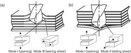
Figure 12 presents the results of the Tukey test, which allows the assessment of the impact of different tools on delamination. In this figure, the tools that do not share the same letter are significantly different, and the error bars include the lowest and highest values of the delamination factor, at a 95%CI, respectively. The analysis of this figure reveals that greater delamination occurs with the T2 tool, characterized by the largest angle. Conversely, as the tool angulation decreases, the extent of delamination diminishes. The T1 and T4 tools showed no significant differences, despite the T4 tool being designed specifically for composite materials. This behavior implies that using either tool T1 or T4 yields similar results in terms of delamination. In contrast, tools T2 (tip angle of 140°) and T3 (tip angle of 90°) yield differing delamination values, which can be attributed to the variance in their tip angles. Similar behavior is reported in the literature (Nayak et al. 2023).

Delamination factor versus cutting tool – Exit. T1: carbide for metallics 118°; T2: carbide 140° for metallic; T3: diamond 90° for composites; T4: carbide for composite 118° and 90°.
CONCLUSION
The performed study investigated the effect of cutting parameters in the drilling process of PEI-based CF-reinforced composite materials, considering the tool rotation, feed rate, and tool geometry, evaluating the delamination occurrence during drilling. Based on the results obtained, it was concluded that the optimal parameters for drilling the test specimens of CF/PEI composites with a 6 mm hole are: diamond tool, rotation of about 4,000 rpm, and feed rate 0.05 mm/tooth.
The correlation of the results obtained allows us to conclude that the diamond tool for hole entry exhibited superior finishing, whereas the carbide tool with a 140° point angle, which is considerably more cost-effective, exhibited minimal delamination. The superior performance of the diamond tool can be attributed, in part, to its specific point angle of 90°. The damage in the entrance hole is influenced by the rotation and geometry of tools, being greater for higher rotation, with a significant difference between 4,000 rpm and 8,000 rpm. It was also observed that the damage at the entrance of the hole is directly influenced by the point angle of the tool, with the 140° point angle showing less damage than the 118° point angle. For the hole exit, the only cutting parameter that directly influenced the outcome was the tool type. In this case, the tool featuring a 118° point angle demonstrated a superior finishing performance in contrast to tools with a 140° point angle. In both cases (entrance and exit), the feed rate does not show a significant influence on the occurrence of delamination. This conclusion was supported by using statistical methods, ANOVA, and Tukey’s test.
For future research, it is recommended to investigate the tool wear and the drilling process in additional thermoplastic composite materials, for example, PEEK and PPS-based CF composites. Furthermore, evaluating tools with sharper tip angles in conjunction with drilling parameters within the range of 4,000 rpm and a feed rate of 0.05 mm/tooth is suggested for further study.
ACKNOWLEDGMENTS
The authors gratefully acknowledge W. Kok and M. Koekenberg from Toray Innovation by Chemistry (Netherlands) for supplying the CF/PEI laminates, and IPT (Brazil) for their support in specimen preparation.
-
DECLARATION OF USE OF ARTIFICIAL INTELLIGENCE TOOLS
It was not used.
-
FUNDING
Coordenação de Aperfeiçoamento de Pessoal de Nível SuperiorFinance code 001Conselho Nacional de Desenvolvimento Científico e TecnológicoGrant No: 306836/2023-8
-
Peer Review History:
Single Blind Peer Review.
DATA AVAILABILITY STATEMENT
All data sets were generated or analyzed in the current study.
REFERENCES
-
Amancio-Filho ST, Roeder J, Nunes SP, Dos Santos JF, Beckmann F (2008) Thermal degradation of polyetherimide joined by friction riveting (FricRiveting). Part I: Influence of rotation speed. Polym Degrad Stab 93(8):1529-1538. https://doi.org/10.1016/j.polymdegradstab.2008.05.019
» https://doi.org/10.1016/j.polymdegradstab.2008.05.019 -
Ameur MF, Hadj Djilani A, Zitoune R V K, Sheikh-Ahmad J, Toubal L, Bougherara H (2022) Experimental and numerical investigations of the damages induced while drilling flax/epoxy composite. J Compos Mater 56(2):295-312. https://doi.org/10.1177/00219983211055825
» https://doi.org/10.1177/00219983211055825 -
Anarghya A, Harshith DN, Rao N, Nayak NS, Gurumurthy BM, Abhishek VN, Patil IGS (2018) Thrust and torque force analysis in the drilling of aramid fibre-reinforced composite laminates using RSM and MLPNN-GA. Heliyon 4(7). https://doi.org/10.1016/j.heliyon.2018.e00703
» https://doi.org/10.1016/j.heliyon.2018.e00703 -
Asyraf MRM, Ilyas RA, Sapuan SM, Harussani MM, Hariz HM, Aiman JM, Asrofi M (2022) Advanced composite in aerospace applications: opportunities, challenges, and future perspective. Adv Compos Aerosp Eng Appl 471-498. https://doi.org/10.1007/978-3-030-88192-4_24
» https://doi.org/10.1007/978-3-030-88192-4_24 -
Babu J, Sunny T, Paul NA, Mohan KP, Philip J, Davim JP (2016) Assessment of delamination in composite materials: a review. Proc Inst Mech Eng B J Eng Manuf 230(11):1990-2003. https://doi.org/10.1177/0954405415619343
» https://doi.org/10.1177/0954405415619343 - Biron M (2007) Thermoplastics and thermoplastic composites: technical information for plastics users. Oxford: Elsevier.
-
Callisaya ES, de Sampaio Alves MC, Kondo MY, Ribeiro MV, Costa ML, Fernandes MF, Botelho EC (2023) Analysis of power consumption during the machining of epoxy based CFRP. Mater Today Commun 37:106993. https://doi.org/10.1016/j.mtcomm.2023.106993
» https://doi.org/10.1016/j.mtcomm.2023.106993 -
Cetex® TC 1000 PEI datasheet. https://www.toraytac.com/media/f1142cc2-2c05-4013-afcb-19c937e5c438/ce4IPQ/TAC/Documents/Data_sheets/Thermoplastic/UD%20tapes,%20prepregs%20and%20laminates/Toray-Cetex-TC1000-Premium_PEI_PDS.pdf
» https://www.toraytac.com/media/f1142cc2-2c05-4013-afcb-19c937e5c438/ce4IPQ/TAC/Documents/Data_sheets/Thermoplastic/UD%20tapes,%20prepregs%20and%20laminates/Toray-Cetex-TC1000-Premium_PEI_PDS.pdf -
Chandrabakty S, Renreng I, Djafar Z, Arsyad H (2019) An optimization of the machining parameters on delamination in drilling ramie woven reinforced composites using Taguchi method. J Phys Conf Ser 1341(5):052005. https://doi.org/10.1088/1742-6596/1341/5/052005
» https://doi.org/10.1088/1742-6596/1341/5/052005 -
Chang DY, Lin CH, Wu XY, Yang CC, Chou SC (2023) Cutting force, vibration, and temperature in drilling on a thermoplastic material of PEEK. J Thermoplast Compos Mater 36(3):1088-1112. https://doi.org/10.1177/08927057211052325
» https://doi.org/10.1177/08927057211052325 -
Ciecieląg K, Skoczylas A, Matuszak J, Zaleski K, Kęcik K (2021) Defect detection and localization in polymer composites based on drilling force signal by recurrence analysis. Measurement 186:110126. https://doi.org/10.1016/j.measurement.2021.110126
» https://doi.org/10.1016/j.measurement.2021.110126 -
De Paula Santos LF, Monticeli FM, Ribeiro B, Costa ML, Alderliesten R, Botelho EC (2023) Does carbon nanotube buckypaper affect mode-I and II interlaminar fracture toughness under quasi-static loading? Compos Struct 323:117507. https://doi.org/10.1016/j.compstruct.2023.117507
» https://doi.org/10.1016/j.compstruct.2023.117507 -
Ekici E, Motorcu AR, Polat A (2022) Optimization and alternative image processing approach for the comprehensive assessment of delamination and uncut fiber in drilling fiber metal laminate. J Braz Soc Mech Sci Eng 44(11):502. https://doi.org/10.1007/s40430-022-03806-2
» https://doi.org/10.1007/s40430-022-03806-2 -
Ekici E, Motorcu AR, Uzun G (2021) Multi-objective optimization of process parameters for drilling fiber-metal laminate using a hybrid GRAPCA approach. FME Trans 49(2). https://doi.org/10.5937/fme2102356E
» https://doi.org/10.5937/fme2102356E -
Ekici E, Motorcu AR, Yıldırım E (2021) An experimental study on hole quality and different delamination approaches in the drilling of CARALL, a new FML composite. FME Trans 49(4). https://doi.org/10.5937/FME2104950E
» https://doi.org/10.5937/FME2104950E -
El Moumen A, Tarfaoui M, Lafdi K (2019) Modelling of the temperature and residual stress fields during 3D printing of polymer composites. Int J Adv Manuf Technol 104:1661-1676. https://doi.org/10.1007/s00170-019-03965-y
» https://doi.org/10.1007/s00170-019-03965-y -
Elfaleh I, Abbassi F, Habibi M, Ahmad F, Guedri M, Nasri M, Garnier C (2023) A comprehensive review of natural fibers and their composites: an eco-friendly alternative to conventional materials. Results Eng 101271. https://doi.org/10.1016/j.rineng.2023.101271
» https://doi.org/10.1016/j.rineng.2023.101271 -
Franke V (2011) Drilling of long fiber reinforced thermoplastics – influence of the cutting edge on the machining results. CIRP Ann 60(1):65-68. https://doi.org/10.1016/j.cirp.2011.03.078
» https://doi.org/10.1016/j.cirp.2011.03.078 -
Gaitonde V, Karnik SR, Rubio JC, Correia AE, Abrão AM, Davim JP (2008) Analysis of parametric influence on delamination in high-speed drilling of carbon fiber reinforced plastic composites. J Mater Process Technol 203(1-3):431-438. https://doi.org/10.1016/j.jmatprotec.2007.10.050
» https://doi.org/10.1016/j.jmatprotec.2007.10.050 -
Ge J, Luo M, Zhang D, Catalanotti G, Falzon BG, McClelland J, Sun D (2023) Temperature field evolution and thermal-mechanical interaction induced damage in drilling of thermoplastic CF/PEKK–A comparative study with thermoset CF/epoxy. J Manuf Process 88:167-183. https://doi.org/10.1016/j.jmapro.2023.01.042
» https://doi.org/10.1016/j.jmapro.2023.01.042 -
Geng D, Liu Y, Shao Z, Lu Z, Cai J, Li X, Zhang D (2019) Delamination formation, evaluation and suppression during drilling of composite laminates: a review. Compos Struct 216:168-186. https://doi.org/10.1016/j.compstruct.2019.02.099
» https://doi.org/10.1016/j.compstruct.2019.02.099 -
Heisel U, Pfeifroth T (2012) Influence of point angle on drill hole quality and machining forces when drilling CFRP. Procedia CIRP 1:471-476. https://doi.org/10.1016/j.procir.2012.04.084
» https://doi.org/10.1016/j.procir.2012.04.084 -
Hocheng H, Puw HY (1992) On drilling characteristics of fiber-reinforced thermoset and thermoplastics. Int J Mach Tools Manuf 32(4):583-592. https://doi.org/10.1016/0890-6955(92)90047-K
» https://doi.org/10.1016/0890-6955(92)90047-K -
Hocheng H, Pwu HY, Yao KC (1993) Machinability of some fiber-reinforced thermoset and thermoplastics in drilling. Mater Manuf Process 8(6):653-682. https://doi.org/10.1080/10426919308934872
» https://doi.org/10.1080/10426919308934872 -
Jayan JS, Appukuttan S, Wilson R, Joseph K, George G, Oksman K (2021) An introduction to fiber reinforced composite materials. Fiber Reinforced Composites 1-24. https://doi.org/10.1016/B978-0-12-821090-1.00025-9
» https://doi.org/10.1016/B978-0-12-821090-1.00025-9 -
Kesarwani S, Verma RK, Jayswal SC (2023) Evaluation of the cutting force, burr formation, and surface quality during the machining of carbon nanoparticle modified polymer composites for structural applications. Mater Today Commun 34:105375. https://doi.org/10.1016/j.mtcomm.2023.105375
» https://doi.org/10.1016/j.mtcomm.2023.105375 -
Kilickap E (2010) Optimization of cutting parameters on delamination based on Taguchi method during drilling of GFRP composite. Expert Syst Appl 37(8):6116-6122. https://doi.org/10.1016/j.eswa.2010.02.023
» https://doi.org/10.1016/j.eswa.2010.02.023 -
Kubher S, Gururaja S, Zitoune R (2021) In-situ cutting temperature and machining force measurements during conventional drilling of carbon fiber polymer composite laminates. J Compos Mater 55(20):2807-2822. https://doi.org/10.1177/0021998321998070
» https://doi.org/10.1177/0021998321998070 -
Kubher S, Gururaja S, Zitoune R (2022) Coupled thermo-mechanical modeling of drilling of multi-directional polymer matrix composite laminates. Compos Part A Appl Sci Manuf 156:106802. https://doi.org/10.1016/j.compositesa.2022.106802
» https://doi.org/10.1016/j.compositesa.2022.106802 -
Kumar G, Rangappa SM, Siengchin S, Zafar S (2022) A review of recent advancements in drilling of fiber-reinforced polymer composites. Compos Part C Open Access 9:100312. https://doi.org/10.1016/j.jcomc.2022.100312
» https://doi.org/10.1016/j.jcomc.2022.100312 -
Mahesh V, Joladarashi S, Kulkarni SM (2021) A comprehensive review on material selection for polymer matrix composites subjected to impact load. Def Technol 17(1):257-277. https://doi.org/10.1016/j.dt.2020.04.002
» https://doi.org/10.1016/j.dt.2020.04.002 -
Mathivanan NR, Mahesh BS, Shetty HA (2016) An experimental investigation on the process parameters influencing machining forces during milling of carbon and glass fiber laminates. Measurement 91:39-45. https://doi.org/10.1016/j.measurement.2016.04.077
» https://doi.org/10.1016/j.measurement.2016.04.077 -
Mazoff J (2003) Drill point geometry. ICS Cutting Tools, Inc. https://www.newmantools.com/champ/Drill_Point_Geometry_nt.pdf
» https://www.newmantools.com/champ/Drill_Point_Geometry_nt.pdf -
McIlhagger A, Archer E, McIlhagger R (2020) Manufacturing processes for composite materials and components for aerospace applications. Polymer Compos Aerospace Ind 59-81. https://doi.org/10.1016/B978-0-08-102679-3.00003-4
» https://doi.org/10.1016/B978-0-08-102679-3.00003-4 -
Meinhard D, Haeger A, Knoblauch V (2021) Drilling induced defects on carbon fiber-reinforced thermoplastic polyamide and their effect on mechanical properties. Compos Struct 256:113138. https://doi.org/10.1016/j.compstruct.2020.113138
» https://doi.org/10.1016/j.compstruct.2020.113138 -
Moussa NB, Sidhom H, Braham C (2012) Numerical and experimental analysis of residual stress and plastic strain distributions in machined stainless steel. Int J Mech Sci 64(1):82-93. https://doi.org/10.1016/j.ijmecsci.2012.07.011
» https://doi.org/10.1016/j.ijmecsci.2012.07.011 -
Nayak BB, Kundu S, Sahu S, Roy S, Das SS (2023) Support vector regression approach for prediction of delamination at entry and exit during drilling of GFRP Composites. E3S Web Conf 391:01162. https://doi.org/10.1051/e3sconf/202339101162
» https://doi.org/10.1051/e3sconf/202339101162 -
Nixon-Pearson OJ, Hallett SR, Withers PJ, Rouse J (2013) Damage development in open-hole composite specimens in fatigue. Part 1: Experimental investigation. Compos Struct 106:882-889. https://doi.org/10.1016/j.compstruct.2013.05.033
» https://doi.org/10.1016/j.compstruct.2013.05.033 -
Ozkan D, Gok MS, Karaoglanli AC (2020) Carbon fiber reinforced polymer (CFRP) composite materials, their characteristic properties, industrial application areas and their machinability. Eng Des Appl III Struct Mater Process 235-253. https://doi.org/10.1007/978-3-030-39062-4_20
» https://doi.org/10.1007/978-3-030-39062-4_20 -
Rawal S, Sidpara AM, Paul J (2022) A review on micro machining of polymer composites. J Manuf Process 77:87-113. https://doi.org/10.1016/j.jmapro.2022.03.014
» https://doi.org/10.1016/j.jmapro.2022.03.014 -
Rubino F, Nisticò A, Tucci F, Carlone P (2020) Marine application of fiber reinforced composites: a review. J Mar Sci Eng 8(1):26. https://doi.org/10.3390/jmse8010026
» https://doi.org/10.3390/jmse8010026 -
Saoudi J, Zitoune R, Gururaja S, Mezlini S, Hajjaji AA (2016) Prediction of critical thrust force for exit-ply delamination during drilling composite laminates: thermo-mechanical analysis. Int J Mach Machinability Mater 18(1-2):77-98. https://doi.org/10.1504/IJMMM.2016.075464
» https://doi.org/10.1504/IJMMM.2016.075464 -
Saoudi J, Zitoune R, Gururaja S, Salem M, Mezleni S (2018) Analytical and experimental investigation of the delamination during drilling of composite structures with core drill made of diamond grits: X-ray tomography analysis. J Compos Mater 52(10):1281-1294. https://doi.org/10.1177/0021998317724591
» https://doi.org/10.1177/0021998317724591 -
Sauer M, Kuhnel MJCC (2019) Composites market report 2019. Carbon Compos 2:1-11. [accessed Jan 6 2025]. https://composites-united.com/media/3988/eng_ccev_market-report_2019_short-version.pdf
» https://composites-united.com/media/3988/eng_ccev_market-report_2019_short-version.pdf -
Scarselli G, Quan D, Murphy N, Deegan B, Dowling D, Ivankovic A (2021) Adhesion improvement of thermoplastics-based composites by atmospheric plasma and UV treatments. Appl Compos Mater 28(1):71-89. https://doi.org/10.1007/s10443-020-09854-y
» https://doi.org/10.1007/s10443-020-09854-y -
Sharma A, Modi S, Bhatla M, Goyal A (2021) Study on machining performance of polymer-based composites by drilling process. Mater Today Proc 47:2878-2882. https://doi.org/10.1016/j.matpr.2021.04.046
» https://doi.org/10.1016/j.matpr.2021.04.046 -
Shyha IS, Aspinwall DK, Soo SL, Bradley S (2009) Drill geometry and operating effects when cutting small diameter holes in CFRP. Int J Mach Tools Manuf 49(12-13):1008-1014. https://doi.org/10.1016/j.ijmachtools.2009.05.009
» https://doi.org/10.1016/j.ijmachtools.2009.05.009 -
Silva TC, Moraes DVO, Morgado GFM, Gonçalves VO, Costa DHS, Marques TPZ, Rezende MC (2024) Mechanical characterization and fractographic study of the carbon/PEI composite under static and fatigue loading. Mech Adv Mater Struct 31(6):1291-1299. https://doi.org/10.1080/15376494.2022.2134952
» https://doi.org/10.1080/15376494.2022.2134952 -
Singh J, Gill SS, Dogra M, Singh R (2021) A review on cutting fluids used in machining processes. Eng Res Express 3(1):012002. https://doi.org/10.1088/2631-8695/abeca0
» https://doi.org/10.1088/2631-8695/abeca0 -
Toro SA, Ridruejo A, González C, Monclús MA, Fernández-Blázquez JP (2022) Optimization of processing conditions and mechanical properties for PEEK/PEI multilayered blends. Polym 14(21):4597. https://doi.org/10.3390/polym14214597
» https://doi.org/10.3390/polym14214597 -
Velayudham A, Krishnamurthy R (2007) Effect of point geometry and their influence on thrust and delamination in drilling of polymeric composites. J Mater Process Technol 185(1-3):204-209. https://doi.org/10.1016/j.jmatprotec.2006.03.146
» https://doi.org/10.1016/j.jmatprotec.2006.03.146 -
Wang B, Liu Z, Cai Y, Luo X, Ma H, Song Q, Xiong Z (2021) Advancements in material removal mechanism and surface integrity of high speed metal cutting: a review. Int J Mach Tools Manuf 166:103744. https://doi.org/10.1016/j.ijmachtools.2021.103744
» https://doi.org/10.1016/j.ijmachtools.2021.103744 -
Wu CQ, Gao GL, Li HN, Luo H (2019) Effects of machining conditions on the hole wall delamination in both conventional and ultrasonic-assisted CFRP drilling. Int J Adv Manuf Technol 104:2301-2315. https://doi.org/10.1007/s00170-019-04052-y
» https://doi.org/10.1007/s00170-019-04052-y -
Yu J, Pan Z, Ye W, Li Q, Wu Z (2023) Dynamic temperature field and drilling damage mechanism of plain woven carbon/glass hybrid composites. Compos Struct 304:116375. https://doi.org/10.1016/j.compstruct.2022.116375
» https://doi.org/10.1016/j.compstruct.2022.116375 -
Zhang LB, Wang LJ, Liu XY (2001) A mechanical model for predicting critical thrust forces in drilling composite laminates. Proc Inst Mech Eng B J Eng Manuf 215(2):135-146. https://doi.org/10.1243/0954405011515235
» https://doi.org/10.1243/0954405011515235 -
Zhang X, Chen J, Li H, Zhu L, Zhou Y, Yan R, Chen M (2025) Research on the thermal-mechanical interaction of the defect evolution and surface generation during the drilling of thermoplastic composites. J Mater Res Technol. https://doi.org/10.1016/j.jmrt.2025.06.127
» https://doi.org/10.1016/j.jmrt.2025.06.127 -
Zitoune R, Collombet F (2007) Numerical prediction of the thrust force responsible of delamination during the drilling of the long-fibre composite structures. Compos Part A Appl Sci Manuf 38(3):858-866. https://doi.org/10.1016/j.compositesa.2006.07.009
» https://doi.org/10.1016/j.compositesa.2006.07.009
Edited by
-
Section editor:
Dimitrios Pavlou https://orcid.org/0000-0002-9522-583X
History
-
Received
24 Sept 2025 -
Accepted
26 Nov 2025 -
Preprint posted on
16 July 2024
10.21203/rs.3.rs-4607334/v1

 Source: Figure 1a: Adapted from
  Source: Elaborated by the authors.
 Source: Elaborated by the authors.
 Source: Elaborated by the authors.
 Source: Elaborated by the authors.
 Source: Elaborated by the authors.
 Source: Elaborated by the authors.
 Source: Figure 8a and b: Adapted from
  Source: Elaborated by the authors.
 Source: Elaborated by the authors.
 Source: Adapted from Mathivanan et al. (2016).
 Source: Elaborated by the authors.


