Experimental Assessment of Finite Control Set - Model Predictive Control Applied to a Dual-Converter-Based Rectifier With a Floating DC link
ABSTRACT
This paper proposes a reduced-computation-burden Finite Control Set - Model Predictive Control (FCS-MPC) applied to a dual-converter-based rectifier with a floating DC link. The main goal of this paper is providing a proof of concept of the discussed system employing the proposed FCS-MPC, highlighting its feasibility, simple multivariable control and straightforward implementation. The proposed FCS-MPC reduces the number of tested vectors from the available 64 to only nine, efficiently controlling grid currents and floating DC-link voltage. To evaluate the performance, steady- and transient-state simulations were carried out to compare the proposed FCS-MPC with the conventional PI-based method. The results indicate that FCS-MPC provides a better dynamic response than the PI-based method. However, its total harmonic distortion (THD) at the same sampling frequency is higher, as the PI-based method benefits from a modulation stage that reduces the current ripple. Additionally, the proposed FCS-MPC shows significantly lower switching losses than the PI-based approach. On the other hand, for the same switching frequency, the proposed FCS-MPC presents a somewhat higher, but similar THD and losses values to the PI-based method. Experimental results further validate the feasibility of the proposed FCS-MPC, reinforcing its potential as an efficient alternative to traditional control strategies in dual-converter-based-rectifier.
KEYWORDS
FCS-MPC; Floating DC link; Open-End Rectifier; Dual Converter; Model Predictive Control; Low Computation Burden
I. INTRODUCTION
Multilevel converters are widely used in applications like wind energy systems, photovoltaic systems, electric vehicles, maglev trains, among others [1]–[3]. The most common multilevel converter topologies include neutral-point clamped (NPC), floating capacitor (FC), and cascaded H-bridge (CHB). The conventional three-phase three-level NPC converter consists of 12 controlled switches and six clamping diodes, while the three-phase three-level FC converter has 12 controlled switches and three additional capacitors. The three-level CHB topology, on the other hand, requires isolated DC sources to supply its DC links. The additional components in NPC and FC converters increase switching and conduction losses, while also reducing reliability due to the higher risk of component failure. In the CHB topology, the need for isolated DC sources typically involves bulky transformers [1]–[3].
Another multilevel topology that has gained a lot of attention is the dual converter [4]–[6]. In this topology, a three-phase source or load has all its terminals connected to power converters on both sides in an open-end configuration. In this way, the most common dual converter uses two two-level converters, employs 12 controlled switches, and does not use additional diodes or capacitors, which is an advantage when compared to NPC and FC. Additionally, when operating as rectifiers, since the power flow is unidirectional in most applications, some of the controlled switches can be replaced with diodes, making the system cheaper and less susceptible to gating failures without compromising the quality of the voltage generated by the converter. This replacement was performed in [7] for an open-end three-phase source feeding a DC load, in [8] for a permanent magnetic synchronous generator (PMSG) feeding a DC load, and in [9]–[11] for a doubly-fed induction generator (DFIG) connected to a DC microgrid. Also, in [12] the authors propose two topologies of unidirectional rectifiers for an open-end three-phase source with cascaded floating capacitor H-bridges.
The dual converter may operate with two isolated DC links [5]. When operating with high modulation index, the two DC-link configuration with equal voltage value for both DC links generates nine-step voltages across the phase terminals (due to the voltage between the two DC-link mid-points, as will be shown in section II). Furthermore, when the DC-link voltage values have a 2:1 ratio (i.e., one DC link has twice the voltage value of the other), the configuration generates 13-step voltages across the phase terminals, providing lower current harmonic distortion with fewer devices than NPC and FC. However, when two isolated DC links are used, they are usually isolated by bulky transformers, presenting the same disadvantage as CHB.
In this way, the most common way of solving this issue is using a single DC link shared by the converters with the cost of generating voltages with a lower number of voltage steps [4], since this configuration operates exactly like an H-bridge, generating a three-step voltage across the phases. However, in order to maintain a voltage waveform with a high number of steps, another alternative is using a floating DC link, as illustrated in Fig. 1(a) [13]. In this configuration (when operating as a rectifier), one DC link feeds a load or is connected to an inverter or to a DC microgrid, and the other DC link floats. The drawback of this alternative is operating with a lower modulation index, and having more complex control and modulation strategies to assure the floating DC-link voltage balancing. The floating DC link must have a lower voltage than the other DC link. This allows the real power to be null in the converter that uses the floating DC link, which is necessary for the floating DC link to keep constant voltage. This alternative may generate phase voltages with up to nine steps.

Dual-converter-based rectifier with a floating DC link. (a) System. (b) Equivalent circuit.
Concerning control strategies, several methods may be employed in power electronics applications to regulate power flow, currents, etc. The most used control methods make use of proportional-integral (PI) controllers associated with a Pulse Width Modulation (PWM) stage. In [13], the authors discuss the system shown in Fig. 1(a) with rectifier B feeding a DC load. The control system makes use of two PI controllers to regulate the voltage of both DC links, and resonant-PI controllers to regulate the grid currents. The voltage ratio between the two DC links is \(v_{Ca}:v_{Cb}=1:2\), meaning that the floating DC link has half the voltage value of the other DC link. The modulation stage employs a modified Level Shift-PWM (LS-PWM) strategy. The modification in the PWM strategy was necessary for proper regulation of the floating DC-link voltage. The disadvantage of this approach is the complexity of the control system, since it may be difficult to tune all controllers properly in order to make the system stable, and also the need of modifying the PWM strategy.
On the other hand, in recent years, the Finite Control Set - Model Predictive Control (FCS-MPC) has gained a lot of attention due to its advantages when compared with PI+PWM strategies, such as fast dynamic response, multivariable control, simplicity, the absence of PI controllers and their design, and a straightforward implementation. According to [14], the FCS-MPC is an algorithm that uses the system model to predict its future behavior and select the best control action to minimize a cost function. Various FCS-MPC methods have been proposed for the dual-converter topology in different applications, such as permanent-magnet synchronous motor drives [15]–[17], induction motor drives [18], [19] and RL loads [20]. The FCS-MPC was also employed in three topologies of dual-converter-based rectifiers in [21]. All topologies made use of two isolated DC links, and the authors proposed a FCS-MPC method that reduces the number of tested vectors.
In this context, one drawback of FCS-MPC is the high computational burden, especially for the multilevel topologies, such as the one studied in this paper. As a result, studies focused on reducing the computational burden of FCS-MPC have been a major area of interest [21]–[25].
Therefore, the present work proposes a low-computational-burden FCS-MPC method applied to a dual-converter-based rectifier with a floating DC link, as illustrated in Fig. 1. This paper is an extended version of conference paper [26], which discussed a FCS-MPC method that tested 46 switching vectors, as will be explained in section III.A. This method has a heavy computation burden, being not implementable in the Digital Signal Processor (DSP). In this new version, the proposed FCS-MPC reduces the number of tested vectors to nine, making the FCS-MPC experimentally implementable. Experimental results were added and a more profound analysis on the system behavior was performed.
A performance comparison between the proposed FCS-MPC and the PI-based strategy discussed in [13] is carried out regarding total harmonic distortion (THD), semiconductor losses, and dynamic response. The experimental results have proven the viability of the proposed technique, as it provides sinusoidal grid current, unity grid power factor, and stable floating DC-link voltage even under current transients.
Summarizing, the main contributions of this paper are 1) demonstrating the feasibility of the dual converter open-end source topology employing the proposed low-computational-burden FCS-MPC, showing its simple multivariable control and straightforward implementation when compared to the PI-based method, which has not been discussed in the literature and 2) providing a performance comparison considering steady and transient states parameters.
II. SYSTEM MODEL
The model of this system is expressed by the three-phase source current dynamics and is given by
where \(j = 1,2,3\). Variable \(e_{gj}\) represents the grid voltages, \(l_g\) and \(r_g\) are the inductance and resistance, respectively, of the filter inductors connected to the grid, and \(i_{gj}\) represents the grid currents. In addition, the other system voltages are given by
where \(v_{gj}\) are the voltages across the phase terminals, \(v_{rj}\) are the converter voltages, \(v_{0a0b}\) is the voltage between DC-link mid-points \(0_a\) and \(0_b\), and \(v_{aj0a}\) and \(v_{bj0b}\) are the pole voltages of rectifiers A and B, respectively. All these voltages are illustrated in the equivalent circuit of the dual converter shown in Fig. 1(b).
The voltage between the DC-link mid-points is given by
And the pole voltages are given by
where \(q_{ja}\) and \(q_{jb}\) are the gating signals of rectifiers A and B, respectively. They may assume the values 1 (meaning that the upper switch of leg \(j\) is closed) or 0 (meaning that the upper switch of leg \(j\) is open). DC-link voltages of rectifiers A and B are \(v_{Ca}\) and \(v_{Cb}\), respectively.
In this way, since the topology uses six two-level legs, there are \(2^6=64\) available switching vectors. The available vectors can be mapped in an \(\alpha\beta\) plane. Considering that the DC-link voltage ratio is \(v_{Ca}:v_{Cb}=1:2\), the space-vector plane is shown in Fig. 2. Each vector is defined based on the switching states as \([q_{1a}\ q_{2a}\ q_{3a}\ q_{1b}\ q_{2b}\ q_{3b}]\). Since the switches’ states are represented as binary variables, the vector number corresponds to its equivalent decimal value, where \(q_{1a}\) is the most significant digit and \(q_{3b}\) is the least significant digit. For example, vector \([q_{1a}\ q_{2a}\ q_{3a}\ q_{1b}\ q_{2b}\ q_{3b}]\) = \([0 1 0 1 0 1]\) corresponds to vector number \(2^4+2^2+2^0\) = 21. Additionally, some of the voltage vectors are mapped at the same place, being named redundant vectors. For example, vectors v47, v18 and v40 are redundant vectors since they are mapped at the same place.
At last, the floating DC-link current and voltage are given by
where \(i_{g1}\), \(i_{g2}\), and \(i_{g3}\) are the three-phase grid currents, and \(C\) is the capacitance of the floating DC-link capacitor.
III. FINITE CONTROL SET - MODEL PREDICTIVE CONTROL (FCS-MPC)
As explained before, the FCS-MPC method is based on the system model. A discrete-time form can be used to predict the future value of the phase currents. For this, the forward Euler discretization method may be used, in which
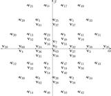
Space-vector of a dual-converter in the \(alphabeta\) plane considering \(v_{Ca}:v_{Cb}=1:2\).

where \(T_s\) is the sampling time, \(i_{gj}(k+1)\) is the predicted value in the next sample, and \(i_{gj}(k)\) is the value in the present sample.
By applying (9) in (1), the expression obtained for the current is
However, the proposed FCS-MPC was implemented using a two-step horizon prediction, as described in [14]. This compensates for the delay introduced by the DSP that appears when one-step horizon prediction is used. Therefore, moving the discrete-time model one step forward in (9), the future phase currents at the sampling instant \((k+2)\) are obtained by
Following the same logic for the floating DC-link voltage, \(v_{Ca}(k+2)\) is given by
By applying the FCS-MPC method, the converter has its gating signals determined by selecting a switching vector that minimizes a cost function. In this case, considering that rectifier B is connected to a DC microgrid (making \(v_{Cb}\) constant), the cost function is based on the currents and floating DC-link errors and is given by
where the asterisk superscript \(^*\) refers to a reference variable and \(\lambda\) is a weighting factor.
A. Proposed FCS-MPC algorithm
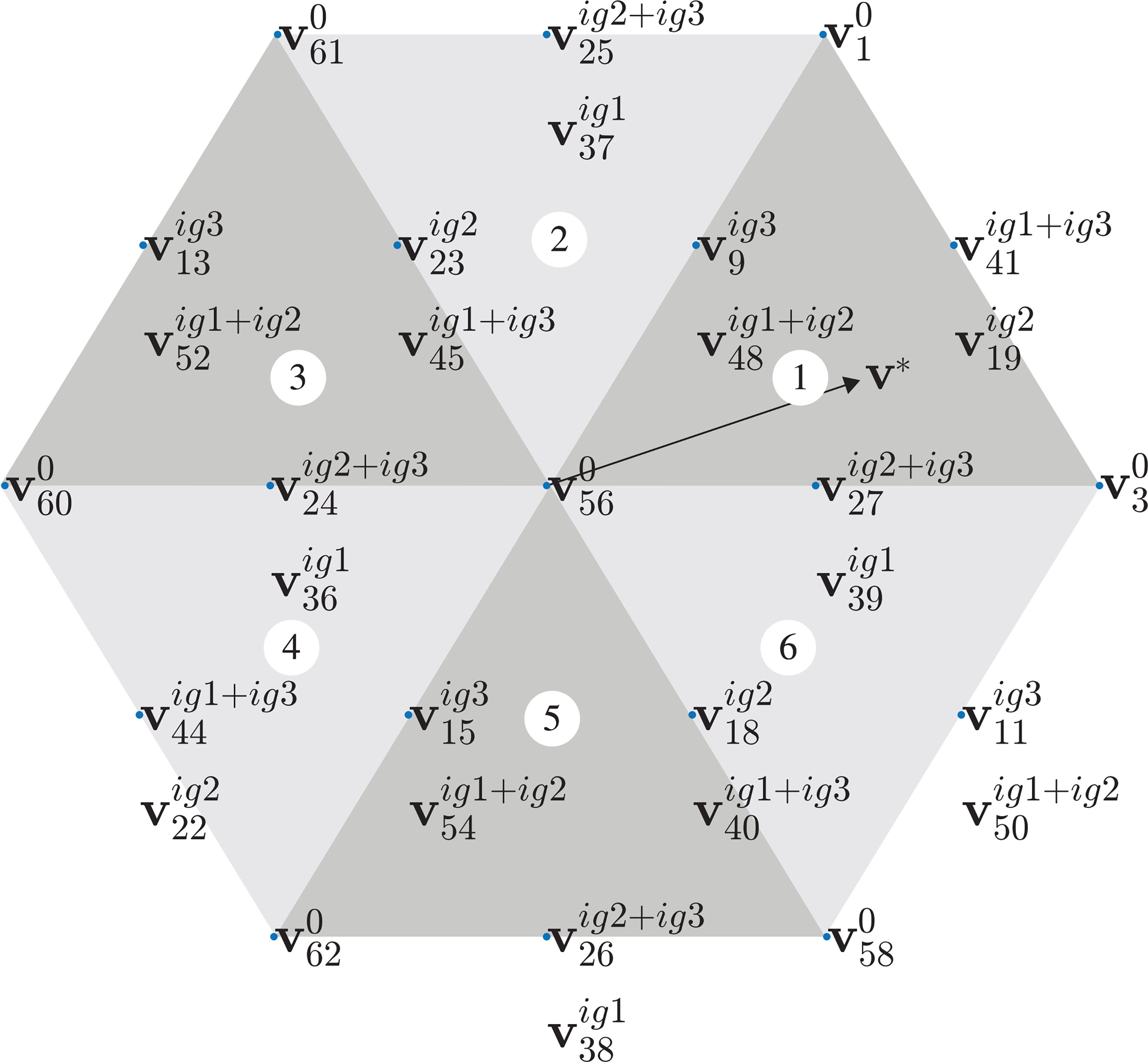
Fig. 3 illustrates the proposed FCS-MPC block diagram. The proposed algorithm has the goal of the reducing the high computation burden of the conventional FCS-MPC. Fig. 2 shows that the 64 switching states generate 37 different voltage vectors for a DC-link ratio of \(v_{Ca}:v_{Cb}=1:2\). Thus, the conventional FCS-MPC tests all 64 switching vectors and applies the vector that minimizes the cost function. However, to ensure the regulation of the floating capacitor, the system must operate with a low modulation index. Consequently, the larger vectors (those forming the outer hexagon on the plane) are not utilized, as explained in [20] and also used in [26], reducing the number of tested vectors to 46.
In order to reduce the computation burden even more, redundancies can be analyzed to simplify the FCS-MPC algorithm. Also, the charge and discharge states of the floating DC link must also be taken into account.
Thus, as expressed in (7), the floating DC-link current depends on the switching state and the grid currents. In order to understand the charge and discharge of the floating DC link, consider once again the redundant vectors v47, v18 and v40. To form vector v18, the switching state of rectifier A is \([q_{1a}\ q_{2a}\ q_{3a}]\) = \([0 1 0]\), resulting in \(i_{Ca} = i_{g2}\). On the other hand, to form vectors v47 and v40, the switching state of rectifier A is \([q_{1a}\ q_{2a}\ q_{3a}]\) = \([1 0 1]\), resulting in \(i_{Ca} = i_{g1}+i_{g3}\). This means that both vectors v47 and v40 have the same influence on the charging state of the floating DC link and one of them can be eliminated from the tests performed by the control algorithm.
Also, the \(\alpha\beta\) plane can be divided into six sectors, as illustrated in Fig. 4. The vectors that are tested in the FCS-MPC algorithm depends on the location of the reference voltage vector, which is obtained by applying the Clarke’s Transformation to 1 as follows:
where the reference voltage vector is given by

Therefore, voltage vectors v47, v18 and v40 are tested in the algorithm when the reference voltage vector is either in sector 5 or in sector 6 (as shown in Fig. 4). In sector 5, it can be demonstrated that \(i_{g1}<0\), \(i_{g2}>0\), and \(i_{g3}>0\), with \(i_{g1}\) having a higher magnitude than \(i_{g3}\). So, v18 charges the floating DC link and vectors v47 and v40 discharge it. In sector 6, \(i_{g1}<0\), \(i_{g2}<0\), and \(i_{g3}>0\), with \(i_{g3}\) having higher magnitude than \(i_{g1}\). This means that v18 discharges the floating DC link, and v47 and v40 charge it. This pattern applies to all redundant vectors, where one vector always charges the floating DC link and another discharges it. And, as explained before, in the cases where there are three redundant vectors, one can be eliminated based on its effect on the DC-link charging state. As shown in Fig. 4, v47 was removed from the control algorithm.
At last, in the proposed FCS-MPC algorithm, each sector tests only nine voltage vectors, as can be observed in Fig. 4. The vectors tested for each sector are listed in Table 1. So, from the conventional FCS-MPC method, which tests all 64 available vectors, the proposed FCS-MPC algorithm was able to reduce the number of tested vectors to only nine, representing a reduction of around 86 % in the number of tested voltage vectors.
IV. SIMULATION RESULTS
Digital simulations were performed for the configuration shown in Fig. 1, considering that rectifier B is connected to a DC microgrid. The filter resistance and inductance were \(r_g=0.5\ \Omega\) and \(l_g=6\) mH, respectively. The amplitude of grid voltage was \(E_g=311\) V. The modulation index was 0.67. In this way, considering a DC-link voltage ratio of \(v_{Ca}:v_{Cb}=1:2\), the DC-link voltage of rectifier B was always constant with \(v_{Cb}=536\) V and the floating DC link of rectifier A had a reference value of \(v_{Ca}^*=268\) V. The capacitance of the floating DC link was \(C\) = 2200 \(\mu\)F. The grid currents were adjusted to be synchronized with the grid phase voltages, providing unity power factor operation.
To compare the performance of the methods, the system was simulated using the proposed FCS-MPC, the FCS-MPC excluding the larger vectors (discussed in conference paper [26]), and the PI-based method described in [13]. For both FCS-MPC methods, a weighting factor of \(\lambda = 0.1\) was used. This value was determined empirically.
A. Steady-State Results
Firstly, to prove that the proposed FCS-MPC operates properly for the dual converter open-end system of Fig. 1(a), simulations for \(f_{samp}\) = 10 kHz were carried out for three different grid current amplitudes: 5 A, 10 A and 15 A. The obtained waveforms are illustrated in Fig. 5. From top to bottom, they are defined as follows: grid voltage and current in phase 1 (\(e_{g1}\) and \(i_{g1}\)), grid currents (\(i_{g1}\), \(i_{g2}\) and \(i_{g3}\)), voltage across phase 1 (\(v_{g1}\)), and floating DC-link voltage (\(v_{Ca}\)). As can be observed, the grid voltage and the grid current are synchronized, guaranteeing unity power factor. The grid currents are sinusoidal, accurately following their respective reference values. The voltage across phase 1 presents nine voltage steps, and the floating DC-link voltage is well-regulated to the reference value.
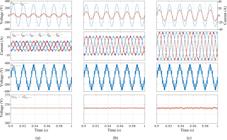
Steady-state waveforms - from top to bottom, grid voltage and current (eg1 and ig1), grid currents (ig1, ig2 and ig3), voltage across phase 1 (vg1), and floating DC-link voltage (vCa) for the proposed FCS-MPC. (a) Ig = 5 A (b) Ig = 10 A (c) Ig = 15 A.
Secondly, to compare steady-state performance in terms of THD, semiconductor losses, and switching frequency, the FCS-MPC method discussed in [26] and the PI+PWM were simulated for the same sampling frequency as the proposed FCS-MPC (\(f_{samp}\) = 10 kHz).
The values of current total harmonic distortion (THD) were obtained from
where \(\gamma_{1}\) is the fundamental current amplitude, \(\gamma_{h}\) is the corresponding harmonic component amplitude of the \(h^{th}\) order, and \(N_{h}\) is the number of considered harmonics.
The semiconductor power losses were estimated using the losses model presented in [27]. The results are summarized in Tables 2-4, where \(P_{cond}\), \(P_{swit}\) and \(P_{tot}\) are the conduction losses, switching losses, and total semiconductor losses, respectively.
The average switching frequency of the dual converter (\(f_{swit}\)), as well as the individual average switching frequencies for rectifiers A (\(f_{sa}\)) and B (\(f_{sb}\)), were obtained. Following the method described in [28], they are given by:
where \(n_{s1a}, n_{s2a}, n_{s3a}, n_{s1b}, n_{s2b}\) and \(n_{s3b}\) are number of commutations of each switch and \(T\) is time period of calculation.
Tables 2-4 present the results for the same sampling frequency (\(f_{samp}\) = 10 kHz). It is possible to conclude that FCS-MPC has a significantly lower average switching frequency than PI+PWM, resulting in reduced switching losses and, consequently, lower total losses. When analyzing the average frequency of each rectifier individually, it is evident that, for all methods, rectifier B (which has the higher DC-link voltage) operates at a lower average frequency than rectifier A. This also contributes to decrease the switching losses. However, the high THD values make FCS-MPC less favorable than PI+PWM in this aspect. So, in this scenario, it is possible to conclude that the proposed FCS-MPC has lower switching frequency and lower losses at the expense of higher current ripple (and higher harmonic distortion) than PI+PWM.

Current harmonic spectra. (a) Proposed FCS-MPC: Ig = 5 A. (b) PI+PWM: Ig = 5 A. (c) Proposed FCS-MPC: Ig = 10 A. (d) PI+PWM: Ig = 10 A. (e) Proposed FCS-MPC: Ig = 15 A. (f) PI+PWM: Ig = 15 A.

Dynamic response waveforms - grid currents and floating DC-link voltage. (a) Change of Ig from 5 to 10 A - Proposed FCS-MPC. (b) Change of Ig from 5 to 10 A - PI+PWM. (c) Change of Ig from 10 to 5 A - Proposed FCS-MPC. (d) Change of Ig from 10 to 5 A - PI+PWM.
So, in order to perform a more complete and fairer comparison, results with the same switching frequency are also presented. In this way, all control methods were also simulated for same switching frequency \(f_{swit}\) = 14 kHz. This value of \(f_{swit}\) was chosen because it is obtained for the PI+PWM method with a sampling frequency of \(f_{samp}\) = 10 kHz.
Therefore, Tables 5-7 present the results for the same switching frequency (\(f_{swit}\) = 14 kHz) for the three current values. Note that, in order to make FCS-MPC switching frequency equal to that of PI+PWM, it was necessary to increase the sampling frequencies for both the proposed FCS-MPC and the FCS-MPC discussed in [26]. The values of the sampling frequencies for this scenario are shown in the Tables.
For this scenario, it is possible to see that all methods present similar values of conduction and switching losses and the values of current THD obtained with the FCS-MPC methods become closer to the ones observed with PI+PWM, but PI+PWM presents somewhat lower values.
In this context, for a sampling frequency of \(f_{samp}\) = 10 kHz, the current harmonic components with \(I_g\) = 5, 10 and 15 A for the proposed FCS-MPC and PI+PWM are illustrated in Fig. 6. Note that FCS-MPC has a spread spectrum, with significant harmonic values in low frequencies, which justifies the high values of harmonic distortion produced by FCS-MPC. On the other hand, PI+PWM produces low-magnitude harmonics around the multiples of the sampling frequency. Also, it is possible to see that, as the fundamental current amplitude \(I_g\) increases, the harmonics become less significant for both methods.
In an overall analysis, FCS-MPC has the tendency of presenting higher THD than PI+PWM. However, the main advantage of FCS-MPC methods over PI-based ones are the simplicity and straight-forward implementation. As explained before, while the authors in [13] had to design properly the PI controllers for the inner loop current controllers and the outer loop DC-link voltage controller (which may be a complicated task since both control loops mutually influence each other and an incorrect design may lead the system to instability) and had to perform modifications in the PWM strategy to be able to regulate the floating DC-link voltage \(v_{Ca}\), the proposed FCS-MPC is able to regulate the currents and floating DC-link voltage by employing a single and simple cost function.
Comparing the FCS-MPC methods, the proposed one has similar results in terms of harmonic distortion, semiconductor losses, and average switching frequency when compared to the one discussed in [26]. This shows that the proposed reduced-computational-burden FCS-MPC method does not compromise the method performance.
At last, the MATLAB\textregistered\ tic toc tool was used to compare the computational burden of the methods. This tool provides the time for the software to perform the algorithm calculations in the code. The results are presented in Table 8. Note that the estimated time may vary depending on the processing capacity of the computer used to perform the simulations. The computer used to calculate the times shown in Table 8 has an Intel(R) Core(TM) i7-8550U CPU 1.80GHz processor. For the FCS-MPC discussed in [26], with 46 tested vectors, MATLAB\textregistered\ took approximately 129.49 \(\mu\)s to calculate the instructions. On the other hand, for the proposed FCS-MPC, which eliminates the charging and discharging redundancies and considers the six-sector operation, MATLAB\textregistered\ took approximately 26.6 \(\mu\)s to execute the control algorithm. This represents a reduction in computation time of approximately 94%. This demonstrates that the reduction in the number of tests significantly decreases the computational burden associated with model predictive control. The lowest computational burden was obtained for the PI+PWM, which is expected, since the method does not have to calculate the current and voltage values for several voltage vectors.
B. Transient-State Results
Two tests were performed to observe the dynamic response for the proposed FCS-MPC and the PI+PWM method. In the first test, the system operated with a current reference amplitude of 5 A until the time of 1.5 s. At this point, the reference amplitude changed from 5 A to 10 A. This result is shown in Fig. 7(a) for proposed FCS-MPC and Fig. 7(b) for PI+PWM. As can be seen, the currents promptly reached the new reference currents when FCS-MPC is employed, with a very smooth dynamic response. On the other hand, when PI controllers and PWM are employed, it takes a longer time to reach the new references.
To better evaluate the system dynamic response, the grid currents were transformed to dq reference frame. This transformation provides DC currents (see Fig. 7). So, for FCS-MPC, it is possible to see that the transition took approximately 82 \(\mu\)s, and for the PI-based method, the transition took approximately 2.5 ms.
On the other hand, in the second test, the system operated with a current reference amplitude of 10 A until the time of 1.5 s. At this point, the reference amplitude changed from 10 A to 5 A. In this case, FCS-MPC presented a more severe transient, as illustrated in Figs. 7(c) for FCS-MPC and 7(d) for PI+PWM. In this case, the currents reached their new references within approximately 2 ms for both FCS-MPC and PI+PWM.
Naturally, for the PI-based case, the transition time depends on the current controller gains. But, even if the gains were changed to reduce the transition time, a higher overshoot would be observed. Moreover, the system stability must be taken into account since there is a floating DC-link voltage PI controller as well, which may influence the current control loop. Thus, because of these issues, the FCS-MPC turns out to present a much simpler implementation than PI-based methods.
Regarding the floating DC-link voltage, both methods provided an adequate response during current transients. However, the floating DC-link voltage is less affected during the current transients when the proposed FCS-MPC was employed.
V. EXPERIMENTAL RESULTS
The experimental results were obtained for the topology shown in Fig. 1 employing the proposed FCS-MPC. The experimental setup (see Fig. 8) is composed of SEMIKRON SKM50GB12T4 IGBT modules, SEMIKRON SKKD 46/12 diode modules, LEM LV20-P voltage sensors, LEM LTS15-NP current sensors, electrolytic capacitors, three 3-kVA 220-V/220-V single-phase transformers, and 6-mH inductors. The used control board was the TMDSDOCK28379D Digital Signal Processor, as illustrated in Fig. 8(b). The open-end grid configuration was obtained by connecting the secondary windings of the transformers to the three 6-mH filter inductors and to rectifiers A and B, while their primary windings were connected to the AC utility power by means of a variac. The DC microgrid was emulated using a capacitor bank fed by a second variac and a diode-bridge rectifier connected to a resistive load in order to dissipate the power provided by the open-end-connected grid.

The grid voltage was set \(E_{g_{, ext{RMS}}}\) = 110 V, and the filter parameters were \(r_g\) = 0.5 \(\Omega\) and \(l_g\) = 6 mH. The reference voltage of the floating DC link was \(v_{Ca}^*\) = 134 V and the other DC link was kept constant with \(v_{Cb}\) = 268 V, resulting in a DC-link voltage ratio of \(v_{Ca}:v_{Cb}\) = 1:2 and a modulation index of 0.67. The capacitance of the floating DC link was \(C\) = 2200 \(\mu\)F, the sampling frequency was 10 kHz, and the weighting factor was \(\lambda = 0.1\). The phase locked loop (PLL) algorithm used to synchronize grid voltages and currents is named power-based PLL (pPLL) and is discussed in [29].
A. Steady-State Results
Initially, the grid current amplitude \(I_g\) was set in 5 A. The steady-state results are shown in Fig. 9. The floating DC-link voltage is well-controlled, and the grid currents are sinusoidal, as illustrated in Fig. 9(a). As can be seen in Fig. 9(b), the grid voltage (\(e_{g_1}\)) and current (\(i_{g_1}\)) in phase 1 are synchronized, ensuring unity power factor operation. In addition, the voltage across phase 1 (\(v_{g_1}\)) is composed of nine voltage steps, as expected for this configuration using the DC-link voltage ratio of 1:2. Therefore, the experimental results of Fig. 9 are in full accordance with the simulations results shown in Fig. 5.

Experimental waveforms in steady-state. (a) Grid currents \(i_{g1}\), \(i_{g2}\), \(i_{g3}\) and the DC-link voltage \(v_{Ca}\). (b) Phase voltage \(v_{g1}\), grid voltage \(e_{g1}\) and grid current \(i_{g1}\).
The execution time of the proposed FCS-MPC on the DSP was obtained by setting a specific GPIO pin to 1 (using the command SET) at the beginning of the control instructions and to 0 (using the command CLEAR) at the end. The instructions go from the capture of the sensors information to the determination of the gating signals. For a sampling frequency of \(f_{samp}\) = 10 kHz (i.e., \(T_s\) = 100 \(\mu\)s), the time to execute all the instructions was only about 21 \(\mu\)s. This means that the proposed FCS-MPC was successful in performing all control instructions with low computational burden.
B. Transient-State Results
The operating performance during a transient was evaluated by changing the current amplitude from 5 A to 10 A and from 10 A to 5 A, as done in simulations. Fig. 10 illustrates the grid currents and floating DC-link voltage waveforms. As can be seen, the floating DC-link voltage was well regulated to its reference, i.e., 134 V for both transients. The currents presented a good dynamic response since the currents quickly followed the new current reference.

Experimental waveforms during a transient of the grid currents \(i_{g1}\), \(i_{g2}\), \(i_{g3}\) and the DC-link voltage \(v_{Ca}\). (a) From 5 A to 10 A. (b) From 10 A to 5 A.
In addition, the dq currents waveforms are presented in Fig. 11. As can be seen, when the current amplitude was changed from 5 A to 10 A, the transition took approximately 0.8 ms. On the other hand, when the change was from 10 A to 5 A, it took approximately 2 ms. Thus, the experimental results corroborate the simulations.

Experimental waveforms during a transient of the dq currents \(i_{gd}\), \(i_{gq}\). (a) From 5 A to 10 A. (b) From 10 A to 5 A.

C. Robustness to Parametric Errors
It is evident that the FCS-MPC methods depend on the model of the controlled system, i.e., for the control strategy to operate properly, the correct values of the system parameters are necessary. Naturally, the values of the parameters may vary due to operating conditions, such as temperature. Therefore, it is necessary to verify how the proposed FCS-MPC performs under parametric variations.
In real life, of course those parametric variations are of hardware physical nature. However, as discussed in [30], [31] for induction motor drives, experimentally implementing parametric variation tests is complex due to the difficulty of physically causing these variations. So, as explained in [30], [31], these tests may be performed by altering the values of the parameters in the control algorithm, while the physical value is considered to remain constant. In this way, the parametric variation tests were carried out by altering the value of the resistance \(r_g\) and the value of the inductance \(l_g\) of the filter inductor in the control algorithm code on the DSP.
To do so, initially, the filter resistance value was changed in the control algorithm following the curve shown in Fig. 12(a). The value of the \(r_g\) was 0.5 \(\Omega\) until 0.5s. At this time, it started to increase until it reached the value of 5 \(\Omega\) at 3.5s, representing an increase of 900 %. Note that the current amplitude slightly increases as the parametric error grows, as shown in Fig. 13(b). On the other hand, the value of the floating capacitor is not affected by this error. In this way, it is possible to conclude that the proposed method is robust to errors in estimation of the the filter resistance.

Experimental waveforms of the grid currents \(i_{g1}\), \(i_{g2}\), \(i_{g3}\) and the floating DC-link voltage \(v_{Ca}\) for the robustness test. (a) Variation of the filter resistance. (b) Variation of the filter inductance.
At last, the filter inductance \(l_g\) had its value changed in the control algorithm, following the curve shown in Fig. 12(b). The value of \(l_g\) was 6 mH until 0.5s. At this time, it started to increase until it reached the value of 20 mH at 3.5s, representing an increase of around 233 %. In this case, the current distortion increases as the parametric errors grows, presenting high ripple and spikes. Notably the proposed FCS-MPC is sensitive to inductance variations, but it is worth pointing out that the control does not diverge despite the high values of parametric errors. Also, proper control of the floating capacitor is performed.
VI. CONCLUSIONS
This paper proposed a reduced-computational-burden FCS-MPC method applied to a dual-converter-based rectifier, in which the number of tested switching vectors is reduced from the available 64 of the conventional FCS-MPC to only nine. The converter uses two DC links, one of which is a floating DC link. The system operated with a 1:2 DC link voltage ratio and a modulation index of 0.67. By means of simulations and experiments, it was possible to see that the proposed FCS-MPC operated properly, adjusting grid currents and floating DC-link voltage to their references. In this way, the obtained experimental results proves the feasibility of the proposed FCS-MPC applied to a dual-converter-based rectifier with a floating DC link.
Also, by means for simulations, the proposed FCS-MPC performance was compared to that of a PI+PWM method for the same sampling frequency (\(f_{samp}\) =10 kHz) and same switching frequency (\(f_{swit}\) = 14 kHz) in terms of THD, semiconductor losses, and switching frequency. In the first scenario, the proposed FCS-MPC has a significantly lower average switching frequency than PI+PWM, resulting in lower switching losses and, consequently, lower total losses. However, the high THD values make FCS-MPC less favorable than PI+PWM in this aspect. In the second scenario, all methods present similar values of semiconductor losses and the values of current THD obtained with the proposed FCS-MPC become closer to the ones observed with PI+PWM, but PI+PWM presents somewhat lower values.
Regarding dynamic response, with a current reference amplitude change from 5A to 10A, the grid currents assume the new reference currents within 82 \(\mu\)s for the proposed FCS-MPC, while the transition took approximately 2.5 ms for the PI-based method. On the other hand, with a current reference amplitude change from 10A to 5A, FCS-MPC presented a more severe transient than PI+PWM, and the system reached the new references in approximately 2 ms for both methods.
In an overall comparison between the two methods, the PI-based has the advantage of having lower THD values than the FCS-MPC for all studied scenarios. On the other hand, the PI-based method is much more complex to design and implement than the proposed FCS-MPC, which does not use PI controllers and provides the control of multiple variables in a single and simple cost function. Then, proposed FCS-MPC provides acceptable control performance, with proper steady and transient behavior, and also simple implementation.
ACKNOWLEDGMENTS
The authors thank the National Council for Scientific and Technological Development (CNPq) and grant 60/2023 Paraíba State Research Foundation (FAPESQ) for the financial support.
-
PLAGIARISM POLICY
This article was submitted to the similarity system provided by Crossref and powered by iThenticate – Similarity Check.
REFERENCES
-
1 J. Rodriguez, S. Bernet, B. Wu, J. O. Pontt, S. Kouro, “Multilevel Voltage-Source-Converter Topologies for Industrial Medium-Voltage Drives”, IEEE Transactions on Industrial Electronics, vol. 54, no. 6, pp. 2930–2945, 2007, doi: 10.1109/TIE.2007.907044.
» https://doi.org/10.1109/TIE.2007.907044 -
2 H. Abu-Rub, J. Holtz, J. Rodriguez, G. Baoming, “MediumVoltage Multilevel Converters—State of the Art, Challenges, and Requirements in Industrial Applications”, IEEE Transactions on Industrial Electronics, vol. 57, no. 8, pp. 2581–2596, 2010, doi: 10.1109/TIE.2010.2043039.
» https://doi.org/10.1109/TIE.2010.2043039 -
3 S. Kouro, M. Malinowski, K. Gopakumar, J. Pou, L. G. Franquelo, B. Wu, J. Rodriguez, M. A. Pérez, J. I. Leon, “Recent Advances and Industrial Applications of Multilevel Converters”, IEEE Transactions on Industrial Electronics, vol. 57, no. 8, pp. 2553–2580, 2010, doi: 10.1109/TIE.2010.2049719.
» https://doi.org/10.1109/TIE.2010.2049719 -
4 K. Sivakumar, A. Das, R. Ramchand, C. Patel, K. Gopakumar, “A three level voltage space vector generation for open end winding IM using single voltage source driven dual two-level inverter”, in TENCON 2009 2009 IEEE Region 10 Conference, pp. 1–5, 2009, doi: 10.1109/TENCON.2009.5396225.
» https://doi.org/10.1109/TENCON.2009.5396225 -
5 K. R. Sekhar, S. Srinivas, “Discontinuous Decoupled PWMs for Reduced Current Ripple in a Dual Two-Level Inverter Fed Open-End Winding Induction Motor Drive”, IEEE Transactions on Power Electronics, vol. 28, no. 5, pp. 2493–2502, 2013, doi: 10.1109/TPEL.2012.2215344.
» https://doi.org/10.1109/TPEL.2012.2215344 -
6 Y. Kumsuwan, W. Srirattanawichaikul, “A space vector modulation strategy for three-level operation based on dual two-level voltage source inverters”, in 2014 International Power Electronics Conference (IPEC-Hiroshima 2014 ECCE ASIA), pp. 3417–3424, 2014, doi: 10.1109/IPEC.2014.6869987.
» https://doi.org/10.1109/IPEC.2014.6869987 -
7 Y. Wang, D. Panda, T. A. Lipo, D. Pan, “Pulsewidth-Modulated DualHalf-Controlled Converter”, IEEE Transactions on Power Electronics, vol. 28, no. 2, pp. 959–969, 2013, doi: 10.1109/TPEL.2012.2204778.
» https://doi.org/10.1109/TPEL.2012.2204778 -
8 Y. Wang, D. Panda, T. A. Lipo, D. Pan, “Open-Winding Power Conversion Systems Fed by Half-Controlled Converters”, IEEE Transactions on Power Electronics, vol. 28, no. 5, pp. 2427–2436, 2013, doi: 10.1109/TPEL.2012.2218259.
» https://doi.org/10.1109/TPEL.2012.2218259 -
9 E. L. Soares, C. B. Jacobina, I. A. C. Oliveira, N. Rocha, V. F. M. B. Melo, “Half-Controlled Converters Connecting Open-End Doubly Fed Induction Generator to a DC-Microgrid”, IEEE Transactions on Industry Applications, vol. 58, no. 5, pp. 6386–6396, 2022, doi: 10.1109/TIA.2022.3187391.
» https://doi.org/10.1109/TIA.2022.3187391 -
10 E. L. Soares, C. B. Jacobina, V. F. M. B. Melo, N. Rocha, E. R. C. da Silva, “Dual Converter Connecting Open-End Doubly Fed Induction Generator to a DC-Microgrid”, IEEE Transactions on Industry Applications, vol. 57, no. 5, pp. 5001–5012, 2021, doi: 10.1109/TIA.2021.3087119.
» https://doi.org/10.1109/TIA.2021.3087119 -
11 E. L. Soares, C. B. Jacobina, N. Rocha, V. F. M. B. Melo, “Dual Converter Operating With Floating Capacitors Connecting Open-End Winding Doubly-Fed Induction Generator to the DC Microgrid”, IEEE Transactions on Industry Applications, vol. 59, no. 5, pp. 6261–6272, 2023, doi: 10.1109/TIA.2023.3288079.
» https://doi.org/10.1109/TIA.2023.3288079 -
12 J. P. R. A. Mello, C. B. Jacobina, M. B. de Rossiter Correa, “Three-Phase Unidirectional Rectifiers With Open-End Source and Cascaded Floating Capacitor H-Bridges”, IEEE Transactions on Industry Applications, vol. 54, no. 3, pp. 2534–2549, 2018, doi: 10.1109/TIA.2018.2804320.
» https://doi.org/10.1109/TIA.2018.2804320 -
13 A. S. Felinto, C. B. Jacobina, J. P. R. A. Méllo, G. A. A. Carlos, I. da Silva, “Power rectifier based on open-end converter with floating capacitor under non-sinusoidal and unbalanced input”, in 2018 IEEE Applied Power Electronics Conference and Exposition (APEC), pp. 3542–3549, 2018, doi: 10.1109/APEC.2018.8341615.
» https://doi.org/10.1109/APEC.2018.8341615 -
14 S. Kouro, P. Cortes, R. Vargas, U. Ammann, J. Rodriguez, “Model Predictive Control—A Simple and Powerful Method to Control Power Converters”, IEEE Transactions on Industrial Electronics, vol. 56, no. 6, pp. 1826–1838, June 2009, doi: 10.1109/TIE.2008.2008349.
» https://doi.org/10.1109/TIE.2008.2008349 -
15 S. Gajanan Petkar, T. Vinay Kumar, “Computationally efficient model predictive control of three-level open-end winding permanent-magnet synchronous motor drive”, IET Electric Power Applications, vol. 14, no. 7, pp. 1210–1220, 2020, doi: 10.1049/iet-epa.2019.0834.
» https://doi.org/10.1049/iet-epa.2019.0834 -
16 S. G. Petkar, V. K. Thippiripati, “A simplified predictive current control of open-end winding permanent magnet synchronous motor”, IEEE Transactions on Power Electronics, vol. 38, no. 1, pp. 816–826, 2022, doi: 10.1109/TPEL.2022.3201337.
» https://doi.org/10.1109/TPEL.2022.3201337 -
17 H.-W. Lee, T.-Y. Yoon, K.-B. Lee, “Model Predictive Control With Space Vector Modulation Based on a Voltage Angle for Driving OpenEnd Winding IPMSM”, IEEE Access, vol. 12, pp. 89026–89034, 2024, doi: 10.1109/ACCESS.2024.3419724.
» https://doi.org/10.1109/ACCESS.2024.3419724 -
18 B. Zhu, K. Rajashekara, H. Kubo, “Comparison between current-based and flux/torque-based model predictive control methods for open-end winding induction motor drives”, IET Electric Power Applications, vol. 11, no. 8, pp. 1397–1406, 2017, doi: 10.1049/iet-epa.2016.0517.
» https://doi.org/10.1049/iet-epa.2016.0517 -
19 K. V. Praveen Kumar, T. Vinay Kumar, “Predictive torque control of open-end winding induction motor drive fed with multilevel inversion using two two-level inverters”, IET Electric Power Applications, vol. 12, no. 1, pp. 54–62, 2018, doi: 10.1049/iet-epa.2017.0209.
» https://doi.org/10.1049/iet-epa.2017.0209 -
20 S. Chowdhury, P. W. Wheeler, C. Gerada, C. Patel, “Model Predictive Control for a Dual-Active Bridge Inverter With a Floating Bridge”, IEEE Transactions on Industrial Electronics, vol. 63, no. 9, pp. 5558– 5568, 2016, doi: 10.1109/TIE.2016.2564949.
» https://doi.org/10.1109/TIE.2016.2564949 -
21 V. F. M. B. Melo, R. C. V. dos Santos, G. M. da Silva Rodrigues, N. Rocha, E. R. C. da Silva, “Finite Control Set Model Predictive Control Applied to Dual-Converter-Based Rectifiers”, in 2020 IEEE Energy Conversion Congress and Exposition (ECCE), pp. 2915–2922, 2020, doi: 10.1109/ECCE44975.2020.9236057.
» https://doi.org/10.1109/ECCE44975.2020.9236057 -
22 S. Vazquez, J. Rodriguez, M. Rivera, L. G. Franquelo, M. Norambuena, “Model predictive control for power converters and drives: Advances and trends”, IEEE Transactions on Industrial Electronics, vol. 64, no. 2, pp. 935–947, 2016, doi:doi=10.1109/TIE.2016.2625238.
» https://doi.org/10.1109/TIE.2016.2625238 -
23 P. Karamanakos, E. Liegmann, T. Geyer, R. Kennel, “Model predictive control of power electronic systems: Methods, results, and challenges”, IEEE Open Journal of Industry Applications, vol. 1, pp. 95–114, 2020, doi: 10.1109/OJIA.2020.3020184.
» https://doi.org/10.1109/OJIA.2020.3020184 -
24 C. Garcia, A. Mora, M. Norambuena, J. Rodriguez, M. Aly, Carnielutti, J. Pereda, P. Acuna, R. Aguilera, L. Tarisciotti, “ModelPredictive Control in Multi-Level Inverters Part I: Basic Strategy and Performance Improvement”, IEEE Open Journal of Industry Applications, 2024, doi: 10.1109/OJIA.2024.3460669.
» https://doi.org/10.1109/OJIA.2024.3460669 -
25 M. Norambuena, A. Mora, C. Garcia, J. Rodriguez, M. Aly, Carnielutti, J. Pereda, C. Castillo, Z. Zhang, V. Yaramasu, et al., “Model Predictive Control in Multi-Level Inverters Part II: Renewable Energies and Grid Applications”, IEEE Open Journal of Industry Applications, 2024, doi: 10.1109/OJIA.2024.3460668.
» https://doi.org/10.1109/OJIA.2024.3460668 -
26 L. M. de Oliveira, V. F. M. B. Melo, I. P. Teles, E. d. L. Soares, E. R. C. da Silva, “Finite Control Set Model Predictive Control Applied to a Dual-Converter-Based Rectifier With a Floating DCLink”, in 2023 IEEE 8th Southern Power Electronics Conference and 17th Brazilian Power Electronics Conference (SPEC/COBEP), pp. 1– 7, 2023, doi: 10.1109/SPEC56436.2023.10408438.
» https://doi.org/10.1109/SPEC56436.2023.10408438 -
27 J. A. A. Dias, E. C. dos Santos, C. B. Jacobina, E. R. C. da Silva, “Application of single-phase to three-phase converter motor drive systems with IGBT dual module losses reduction”, in 2009 Brazilian Power Electronics Conference, pp. 1155–1162, Sept 2009, doi: 10.1109/COBEP.2009.5347623.
» https://doi.org/10.1109/COBEP.2009.5347623 -
28 V. Yaramasu, B. Wu, Model predictive control of wind energy conversion systems, John Wiley & Sons, 2016, doi: 10.1002/9781119082989.
» https://doi.org/10.1002/9781119082989 -
29 R. M. Santos Filho, P. F. Seixas, P. C. Cortizo, L. A. B. Torres, A. F. Souza, “Comparison of Three Single-Phase PLL Algorithms for UPS Applications”, IEEE Transactions on Industrial Electronics, vol. 55, no. 8, pp. 2923–2932, 2008, doi: 10.1109/TIE.2008.924205.
» https://doi.org/10.1109/TIE.2008.924205 -
30 F. Wang, S. Li, X. Mei, W. Xie, J. Rodríguez, R. M. Kennel, “ModelBased Predictive Direct Control Strategies for Electrical Drives: An Experimental Evaluation of PTC and PCC Methods”, IEEE Transactions on Industrial Informatics, vol. 11, no. 3, pp. 671–681, 2015, doi: 10.1109/TII.2015.2423154.
» https://doi.org/10.1109/TII.2015.2423154 -
31 L. M. de Oliveira, V. F. M. B. Melo, G. F. da Paz, F. V. Rocha, E. L. L. Fabricio, “Experimental Assessment of Predictive Current Control Applied to Induction Machine Drive Systems Operating Under Single-Phase Open-Circuit Fault”, Eletronica de Potência , vol. 29, p. e202401, Mar. 2024, doi: 10.18618/REP.2024.1.0011.
» https://doi.org/10.18618/REP.2024.1.0011
Edited by
-
Associate Editor
Filipe P. Scalcon https://orcid.org/0000-0002-8976-2188
-
Editor-in-Chief
Heverton A. Pereira https://orcid.org/0000-0003-0710-7815