Sliding mode combined with PI controller applied for current control of grid-connected single-phase inverter under distorted voltage conditions
ABSTRACT
Grid-connected inverters must be synchronized with the electrical grid to ensure stability and efficiency. However, abrupt grid distortions and harmonic components can degrade the controller’s performance. This paper proposes a sliding mode controller combined with a PI controller for current control in a single-phase grid-connected inverter to enhance Total Harmonic Distortion performance. The primary contribution of this work is the development of a nonlinear controller with a constant switching frequency, addressing the common chattering problem in sliding mode controllers while maintaining adequate performance under distorted voltage conditions using a Phase-Locked Loop. The controller’s performance was evaluated through laboratory experiments under normal and distorted grid conditions, and the results were compared with a repetitive controller, demonstrating its effectiveness in suppressing harmonics in regular operation and under distorted grid voltage conditions.
KEYWORDS
Grid-connected inverters; Harmonic suppression; Single-phase inverter; Sliding mode control; Voltage distortion
I. INTRODUCTION
Renewable energy sources have become essential to meet the growing global energy demand today and in the future. In this regard, grid-connected inverters have evolved significantly, standing out for their efficiency, reliability, and cost [1]. In this context, current control plays a fundamental role in the quality of the energy to be injected into the grid. Systems must guarantee synchronization and correction of any disturbances, requiring robust control techniques, fast dynamic response, and the ability to reject grid disturbances [2].
Voltage source inverters (VSI) generally use L or LC filters for connection to the grid due to their simplicity of implementation to attenuate harmonics. However, at low frequencies, these topologies become bulky and costly. Although LCL filters provide better performance in suppressing harmonics, they introduce a resonant pole that increases the complexity of the control [3]. Therefore, the adopted control strategy must consider the filter topology to ensure compliance with the total harmonic distortion (THD) limits established by international standards [4], [5].
Among the control approaches available are proportional resonant control, which requires proper tuning for satisfactory system operation, and hysteresis control applied to single-phase inverter current control [6]. Fuzzy logic control combined with sliding mode control, which depends on the designer's knowledge of the details of the system, is discussed in [7]. Neural network control is applied in [8], requiring careful selection of networks for training. Discrete and repetitive control [9] and predictive control [10] depend on proper mathematical modeling, and if these characteristics are not considered, they can degrade system performance.
Sliding mode control (SMC) has emerged as a non-linear control alternative for applications in grid-connected inverters. Its ability to deal with unmodeled dynamics, fast dynamic response, and low implementation complexity stands out. [11]. However, the high switching frequency can result in chattering, impacting the system's efficiency [12].
Numerous studies have focused on sliding mode control, which is applied to grid-connected inverters with LCL filters. [13] propose an innovative super-twist integral sliding mode control (ST-ISMC) technique for a three-phase grid-connected inverter with an LCL filter. The approach aims to guarantee convergence in finite time and mitigate vibration problems within the stationary reference frame, in addition to minimizing computational processing demands. Using higher-order sliding mode control techniques, [14] investigate the effects of the sensor on the control of an active shunt filter connected to the LCL-type grid. The authors propose second-order and higher-order continuous controllers, which present greater efficiency than conventional discontinuous sliding-mode control, especially for grid voltage distortions. [15] propose an observer-based sliding mode control to improve stability in LCL-filtered three-phase inverters. This methodology minimizes parametric uncertainty and external disturbances while preserving excellent dynamic performance and robustness. In the work of [16]. A sliding mode control is proposed for inverters with L and LCL filters. This approach aims to improve robustness and dynamic performance under different operating conditions, as in [17], a discrete SMC controller regulates a three-phase inverter, ensuring good dynamic and static performance for single-phase inverters.
In addition, current control strategies for inverters connected to distorted voltage grids are discussed in [18]- [21].
Therefore, this article focuses on developing a Sliding Mode Control Combined with PI (SMCPI) algorithm for a single-phase inverter to control the current injected into the power grid using a constant switching frequency. It also considers modeling the filter and the characteristics of the grid. The article's novelty lies in adapting the sliding mode control (SMC) strategy combined with proportional-integral (PI) control for single-phase inverter applications. The effectiveness of this approach has been demonstrated in motor control, described in [22], as well as in the grid input converter [23].
The SMC technique has the disadvantage of chattering. Therefore, in addition to combining with PI, the proposed technique uses a linear eval function with a saturation switching function at the output of the control signal to avoid this problem. This causes the system to be attracted to the sliding surface at any operating point. In addition, the filter modeling considers the output inductances and the power grid, and applying a constant switching frequency further increases its robustness, making it a reliable option regardless of the characteristics of the power grid, ease of implementation and low computer processing are other key features that make the SMCPI alternative a practical and viable choice.
The adjustment of the controllers was similar to that applied by [24], which made it possible to achieve stability so that the system worked satisfactorily. The results of the proposed SMCPI and the comparison with repetitive controller solutions demonstrate its superior performance.
This article is organized as follows: Section II describes the system under study. Section III details the development of the Sliding Mode Control approach. Section IV describes the methodology adopted and the experimental setup. Section V discusses the results obtained, and Section VI concludes with the findings.
II. SYSTEM DESCRIPTION
A. Operating principles of the single-phase inverter with LCL filter
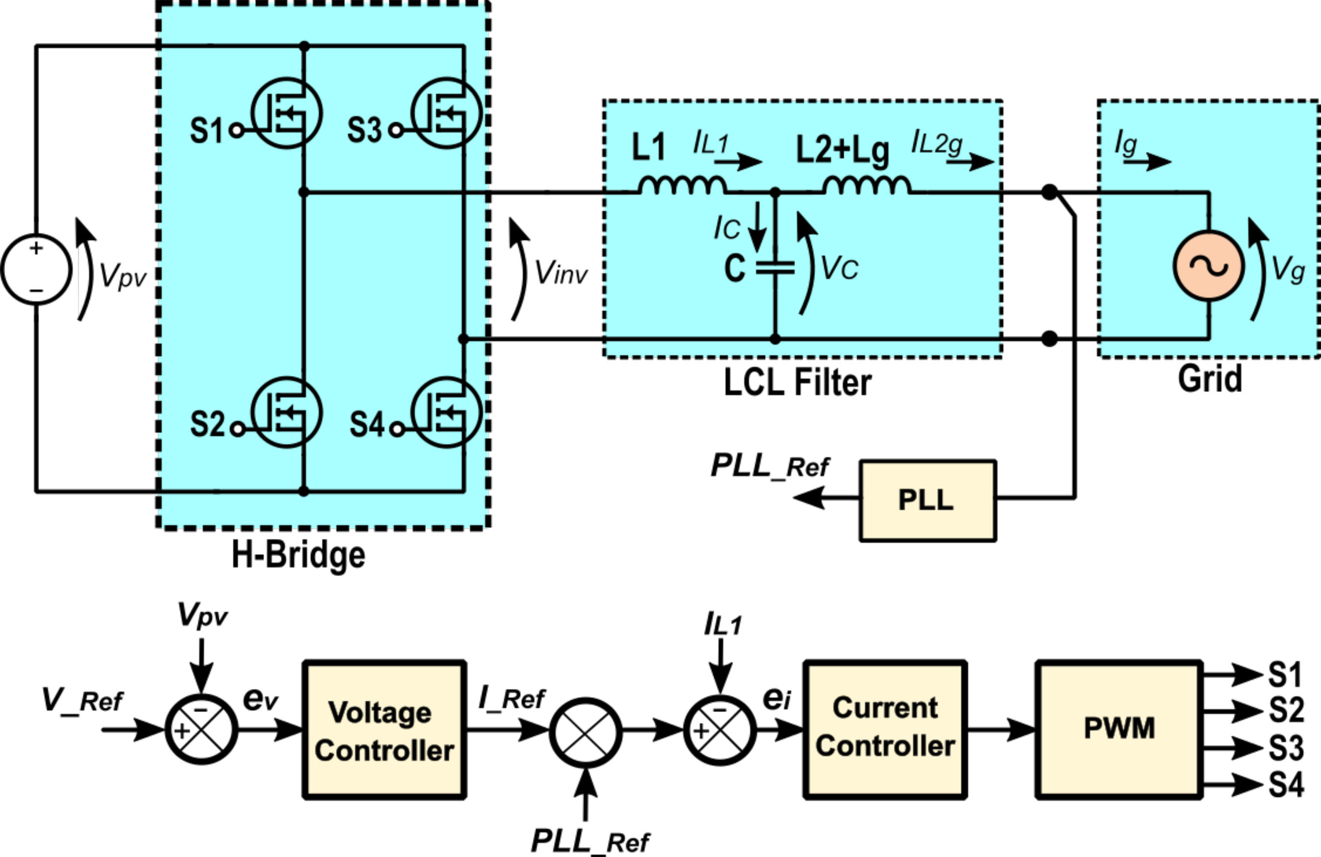
Figure 1 illustrates the topology used for the single-phase inverter configured as a Voltage Source Inverter (VSI). In this sense, the inverter's input DC voltage is regulated while the internal driver generates a current reference for AC output control.
The interface with the electrical grid is carried out through an LCL filter, where represents the filter capacitance, while and provide the inductances of the filtering stage. The grid inductance, , is combined with to form an equivalent inductance. This approach enhances the system's robustness by alleviating the impacts of fluctuations in grid impedance, which may be indeterminate or subject to change over time [25].
Inverter modeling and current control design are essential to ensure correct system operation. In this context, control is implemented directly over the grid oscillating variables without conversion to a stationary or synchronous reference. Thus, algorithms must deal directly with time-varying sinusoidal signals, requiring effective strategies to reduce errors and improve system response. The driver design must guarantee stability and rapid dynamic response, facilitating the efficient operation of the single-phase inverter. Synchronization with the electrical grid is achieved by a Phase-Locked Loop (PLL) that generates a reference signal that is phase- and frequency-synchronized with the grid. In applications affected by harmonic distortions, it is imperative to employ resilient PLL algorithms that can effectively reject disturbances and ensure synchronization accuracy [26].
The modeling of the LCL filter was based on the approaches described in [27]- [29], where the grid inductance is considered a relevant parameter for the filter behavior and its resonant frequencies.
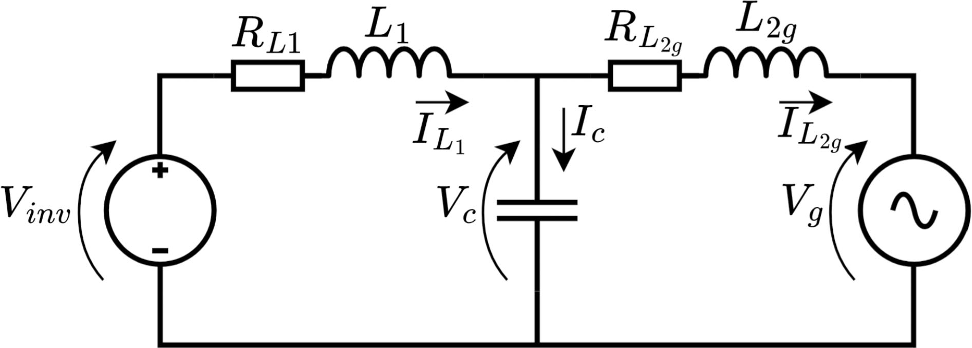
To modeling process, the simplified circuit of the LCL filter shown in Figure 2 was employed, where the inductance's and were considered a single inductance, referred to as , following the approach adopted in [27], [30]. The same methodology described in [31] was utilized to derive the equations, where the modeling is developed for a three-phase system with stationary reference . At the same time, this work applies this methodology to a single-phase system.
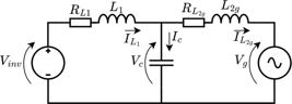
The model can be described considering the parasitic resistances of the inductor, thus obtaining the dynamic model of the system as follows:
III. SLIDING MODEL CONTROL
Traditional sliding mode controllers operate at high and variable switching frequencies, which can result in switching losses and undesired electromagnetic interference [32]. Therefore, careful design of the sliding mode control system is necessary, considering the definition of the sliding surface and the determination of the appropriate control law.
The first step in designing this type of control is to define the sliding surface, which is based on the error between the measured variable and the desired reference. This surface is designed to ensure the system's dynamic stability. Next, it is necessary to determine the control law that will guide the system trajectories toward the sliding surface and keep the states close to it.
Correctly combining the sliding surface and control law is essential for the efficient performance of the sliding mode-controlled system. This approach offers advantages in robustness and disturbance rejection, making it an attractive option for controlling complex dynamic systems.
A. Design Sliding Mode Control combined with PI applied a current controller.
This work proposes the application of a sliding mode current controller combined with a proportional-integral controller using constant switching frequency.
For the controller project, it is essential to determine the initial phase of the proposed system. This phase covers states that have not yet reached the slide surface [22], for this, it is necessary to define a sliding surface.
Initially, the error related to the reference with the controlled variable, in this case, the current through, was obtained the error related to the reference with the variable controlled, in this case, the current through the inductor . Thus, the error is described as follows:
The voltage controller generates the current reference signal to control the DC link voltage. The inductor current and the reference signal define the slip surface S according to the following expression:
The constant is a gain defined according to the desired dynamic response of the system.
After establishing the sliding surface, the control law is determined to guide the trajectories toward this surface and keep them on it. The control aims to bring the system state to the equilibrium point defined on the sliding surface () and maintain it at this equilibrium point.
Using the error obtained from Equation (2), the current controller generates a voltage value proportional to the duty cycle. This voltage value is then converted by a unipolar PWM modulator, ensuring the correct transistor switching sequence. This choice of modulation strategy implies the use of a fixed frequency as described in [11] is the recommended option for single-phase inverter applications.
Thus, the control law that governs the behavior of the proposed controller is described by (4)
Where and are the gains applied to the PI controller and function eval to determine the reaction of the system as a function of the position in the state space, applied to slip surface S.
As presented in (1) the inverter voltage can be described in (5):
is the voltage in the inductor, is the voltage in the capacitor, and voltage drop across the internal resistance in the inductor.
The eval function is essential for determining how the system reacts to the state's position in state space. Three types of eval functions can used in Sliding mode control: sign, hysteresis, and linear function with saturation [33].
The linear function with saturation uses a straight line with maximum and minimum values. The slope of the straight line, , affects the system's dynamics. Therefore, linear eval function with saturation was chosen based on [34], [35], which is applied in studies with single-phase inverters using SMC. The linear evaluation function with saturation mitigates chattering by smoothly reducing oscillations near the sliding surface, enhancing system stability and performance. Due to these characteristics, it has been chosen for use in this work, and the following equation gives its definition (6):
Combining (4) and (5) the dynamic behavior was obtained from the chain as follows (7):
The controller gains were adjusted to enhance the transient response and minimize oscillations. The adjustment process, detailed in [24], involved analyses of open-loop transfer, phase margin, and gain. The driver cutoff frequency was set one decade below the switching frequency to ensure a good dynamic response and eliminate noise. The final parameters obtained were and , with adjusted empirically based on the system response, the validity of the proposed adjustment confirmed through simulations followed by experimental implementation.
A relevant aspect is the robustness of the proposed control regarding disturbances to which the system is submitted [36].
The procedure controller design requires that the VSI gains are large enough to compensate for model uncertainties perturbations and ensure stability [22]. The sliding surface S incorporates a dynamic term weighted by gain to ensure a fast and stable response to disturbance,
It can be proved that values of proportional gain are large enough to satisfy the following stability condition described by (8) [37].
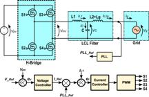
For understanding, the block diagram illustrated in Figure 3 describes the implementation of voltage and current controllers. The voltage block uses a proportional-integral (PI) controller to stabilize the DC link voltage and generate a current reference, along with the synchronization signal from the PLL, and this current reference is then applied to the current controller.

B. Repetitive controller
The repetitive control used in this work is based on the system implemented by [24], aiming to eliminate periodic disturbances and track harmonic references.
The function that describes the behavior of the repetitive controller is given by:
Where T is the fundamental period of the signal and the delay positions the poles at the odd harmonic frequencies of the input signal.
However, due to the repetitive controller's limitations in terms of transient response, it is often combined with a PI controller to improve the system's dynamics; an adequate adjustment of the PI and the gain of the repetitive controller ensures a fast response in the transient regime.
IV. METHODOLOGY
A. Configuration of Normal Voltage and Distorted Voltage Tests
In the comparative study of the proposed controllers under normal operating conditions, a controllable electronic power supply was configured with an output voltage of 127VAC, without distortion, and a fundamental frequency of 60 Hz.
The power supply was adjusted for the test under distorted voltage conditions to introduce harmonic distortions in the 3rd, 5th, and 7th harmonic components without phase shift between the sinusoidal components. The values used for each element were inspired by [38] and are presented in Table 1, where the magnitudes of the harmonic components expressed as a percentage of the voltage magnitude of the fundamental harmonic. This fundamental magnitude is a reference for the other signals in terms of amplitude, enabling a comparative analysis of the distortion levels. The THD of the grid voltage was measured both under normal operation and distorted conditions, presenting values of 0.58% and 8.96%, respectively.
The scenario of perturbation in the power grid and regular operation was used to evaluate controllers behavior and characteristics, such as step response time and THD, to assess their performance and stability under various conditions.
B. Experimental Setup, Data Collection, and Performance Evaluation Parameters
The experimental implementation used the TMDSSOLARP-EXPKIT hardware from Texas Instruments™ [39] for validation. The proposed controllers were implemented to control a single phase inverter using the TMS320F28035 fixed-point digital signal processor (DSP), which was selected to demonstrate the ease of implementation and efficiency of the proposed work, highlighting its suitability for DSPs with limited resources. The control algorithms were developed in C language, using the Texas Instruments Code Composer Studio (CCS) development environment,with the ADC capture rate set to 20kHz for current and voltage reading.
The control system uses an H-bridge converter that operates at a fixed frequency of 20kHz and employs an LCL filter. The experimental tests were carried out with an input voltage of 30Vdc and an output voltage of 12 Vac, with a resistive load connected to the output. All tests were in accordance with the hardware specifications and manufacturer's recommendations [39], as indicated in Table 2.
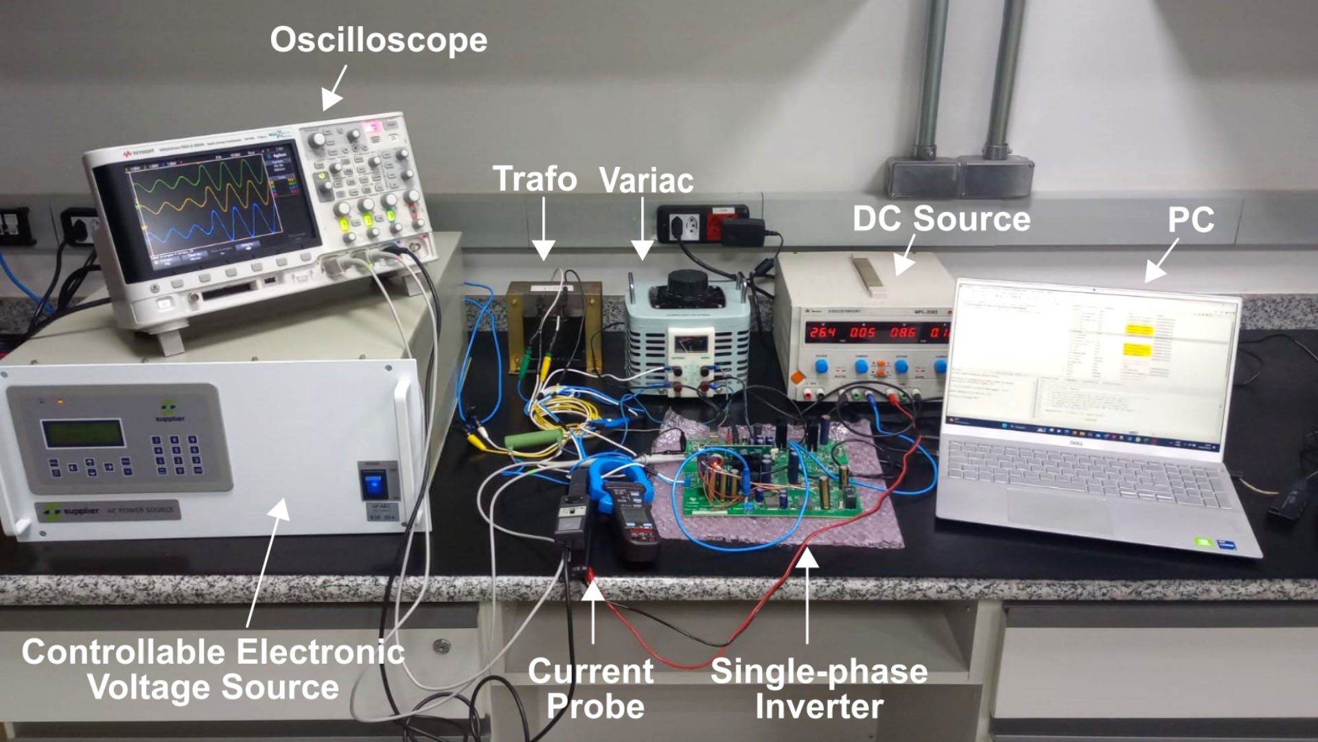
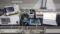
A 1:10 turns ratio transformer established the connection between the inverter and a controllable electronic power supply that simulates normal and distorted voltage conditions.
The DSP's digital-to-analog converter (DAC) provided the reference current and output current signals. These signals were superimposed to demonstrate the correct operation of the controllers, where the output current should follow the requested reference.
The results were obtained through tests conducted on the test bench, and the oscilloscope recorded the data in CSV files. The data were later analyzed using Matlab/SimulinkTM software. These results allowed for the analysis of parameters such as response time and THD.
Figure 4 presents the arrangement of the test bench described.
V. EXPERIMENTAL RESULTS
A. Analysis of Controllers under Normal Operating Conditions
This section compares the proposed SMCPI with a repetitive controller implemented based on the approaches presented by [24], [40]. Both controllers were applied to the current control.
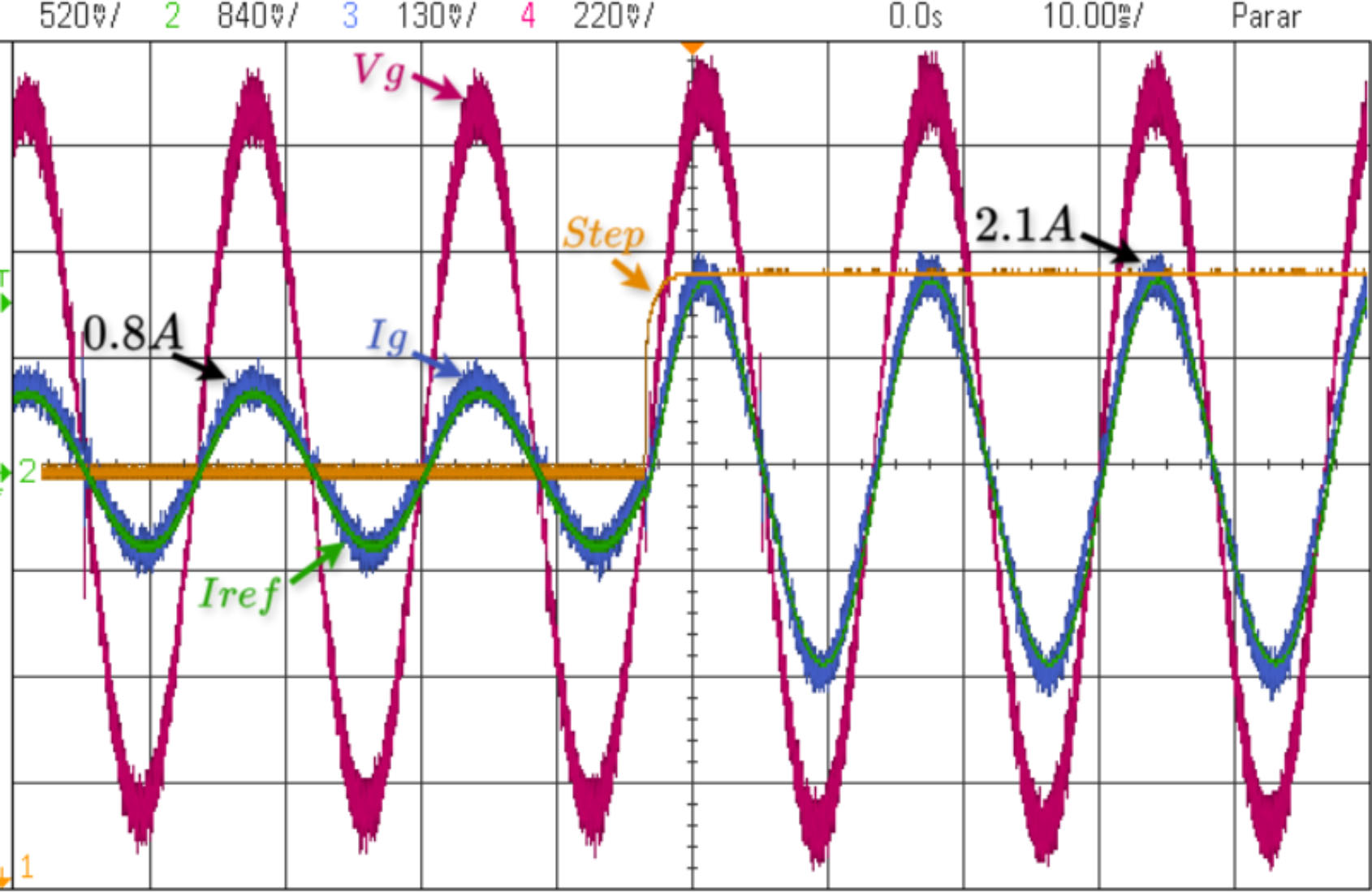
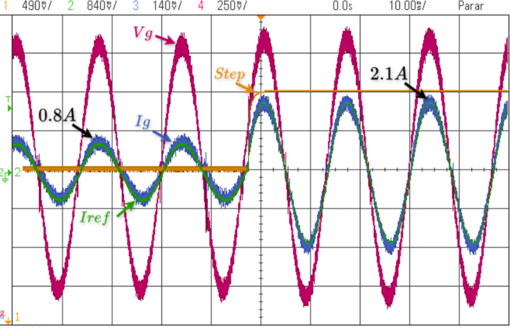
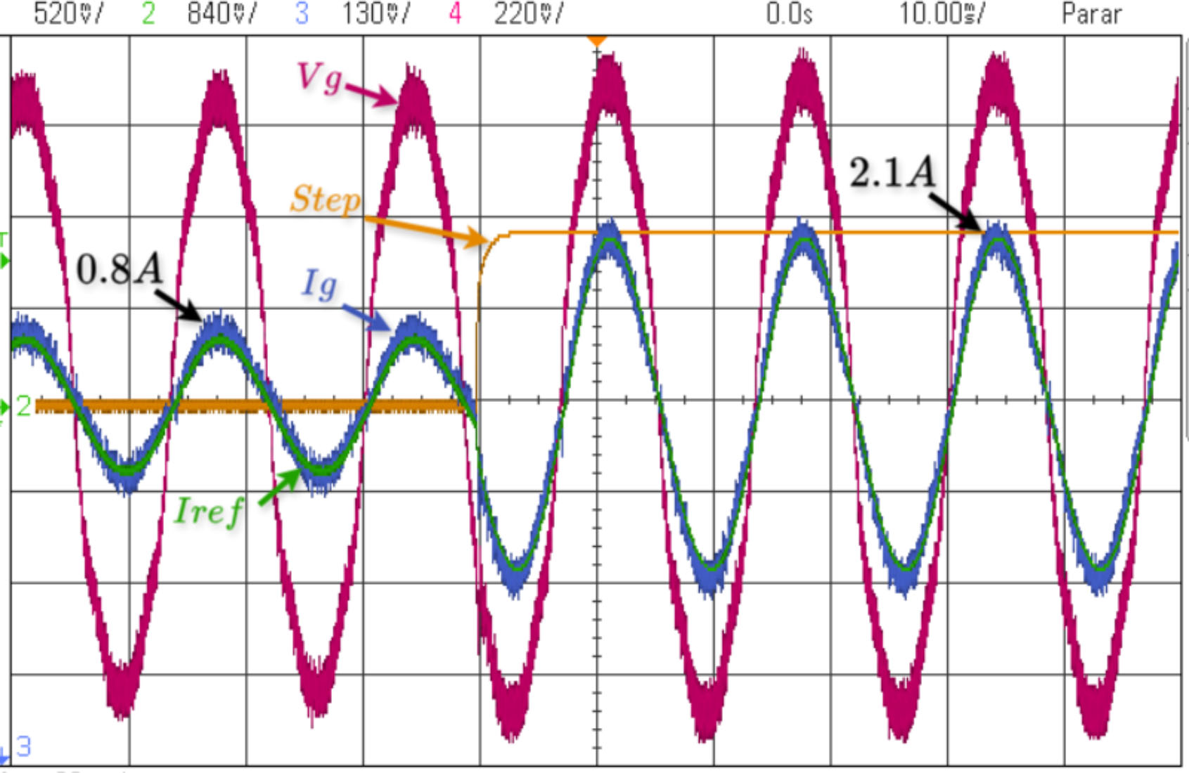
The initial test to evaluate controllers under regular operation involves applying a step current ranging from 0.8A to 2.1A.
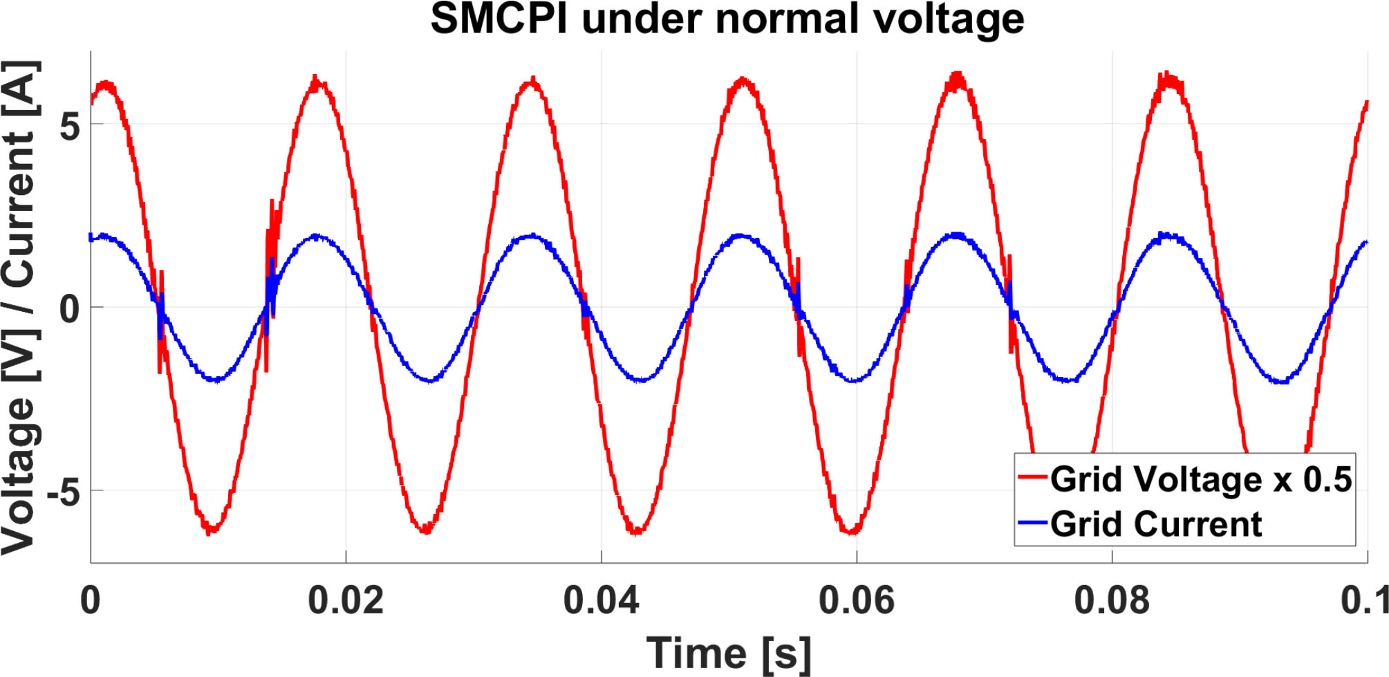
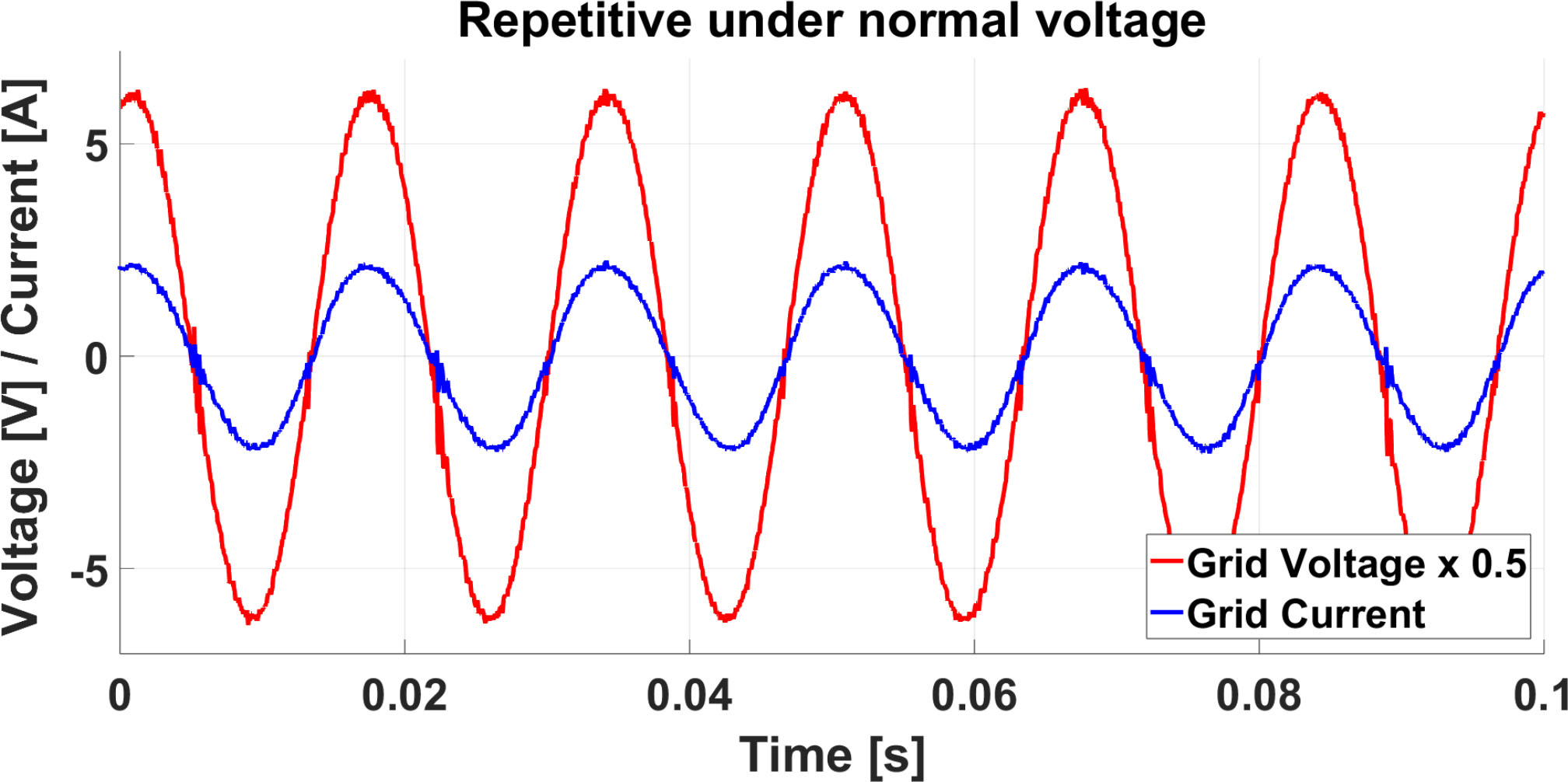
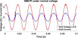
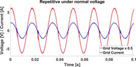
Figures 5 and 6 illustrate the dynamic response of the current injected into the power grid with respect to the design step for the system test. It can be observed that the grid voltage is in phase with the injected current.

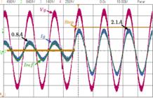
In this test, the power grid voltage consists only of the fundamental harmonic at 60Hz with a magnitude of 12Vac due to the 1:10 turns ratio of the isolation transformer. It is noticeable that the controller reaches the desired reference in response to the change in the current step. Additionally, the voltage undergoes a slight increase in value, possibly due to the increased current across the load resistance of . The controller will be applied to the same system in the subsequent subsection, but the voltage will be subject to distortions as described in the previous section A.
B. Analysis of Controllers under Distorted Voltage Conditions
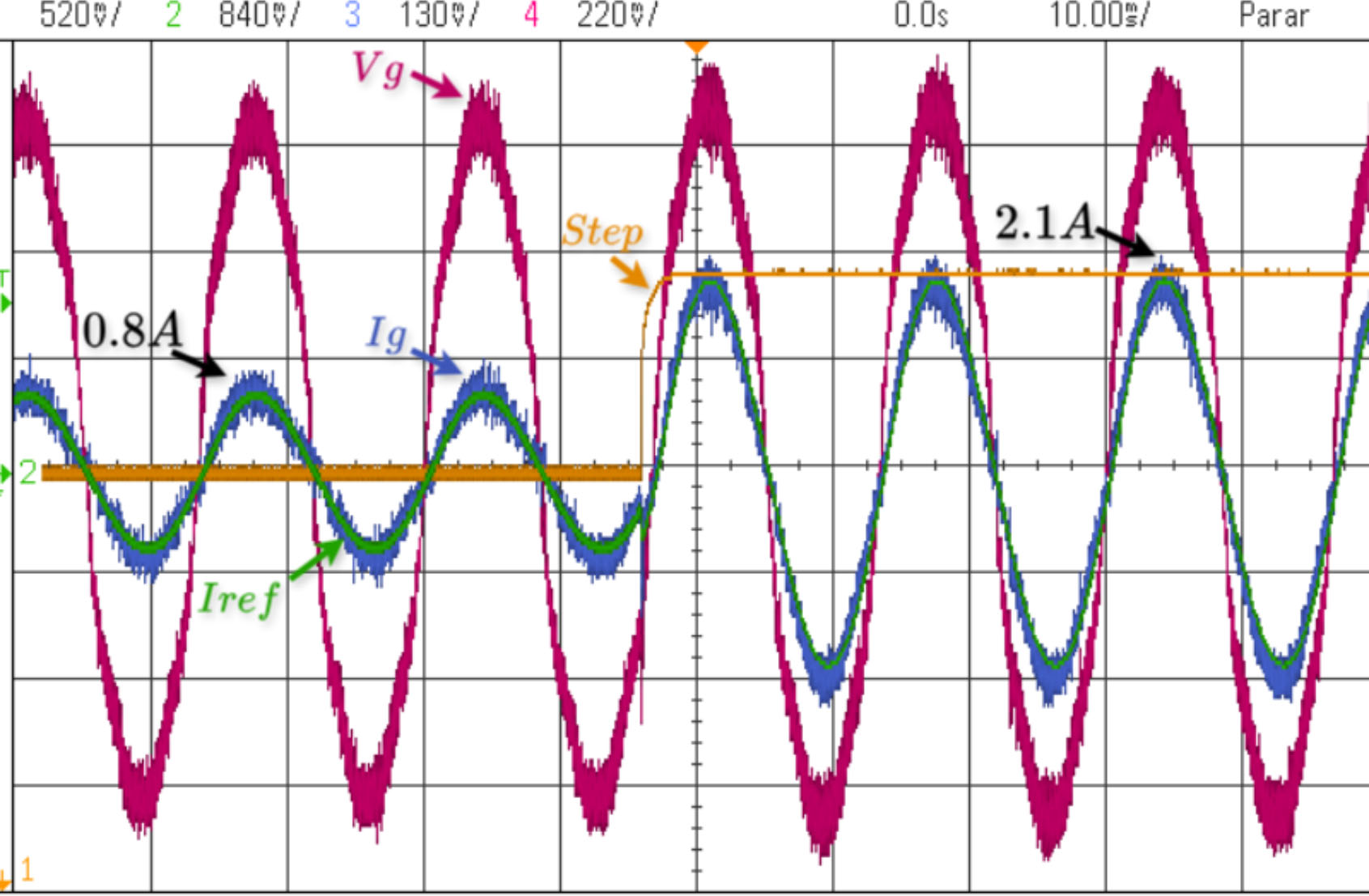
Including harmonic distortions in the power grid voltage is crucial for evaluating the proposed controller, as these disturbances can degrade the control system's performance. The introduced harmonics represent real-world scenarios to which power grids are subjected.
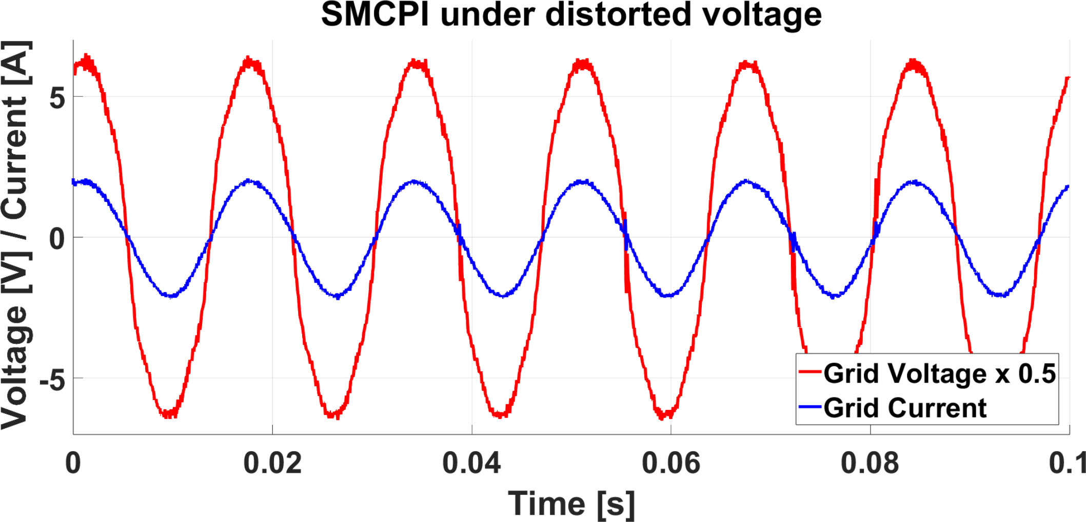
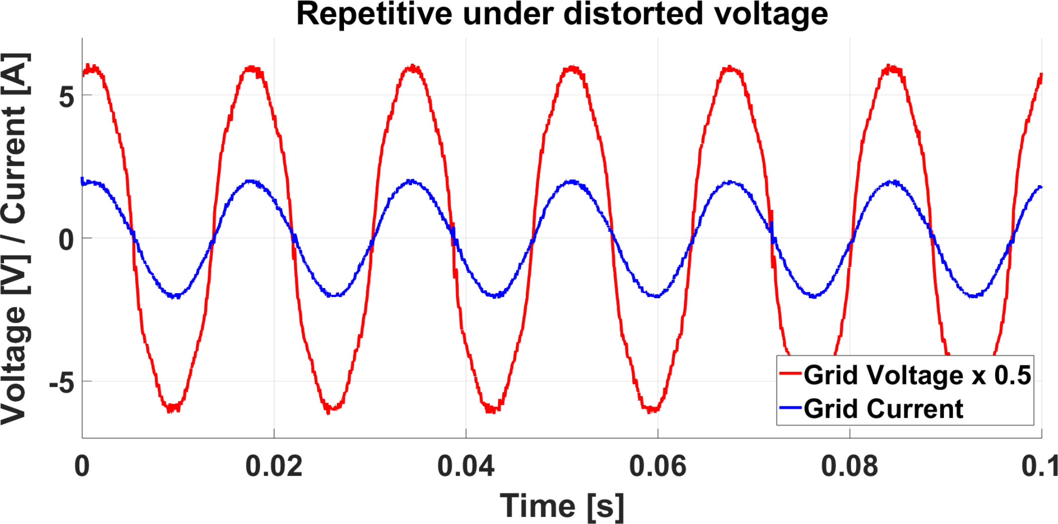
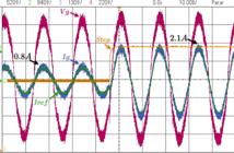
Figures 7 and 8 present the dynamic response of the injected current into the power grid under distorted voltage conditions concerning the step established by the designer, similar to the test without distorted voltage for system evaluation.

C. Evaluation of Experimental Results and Performance Comparison between Controllers
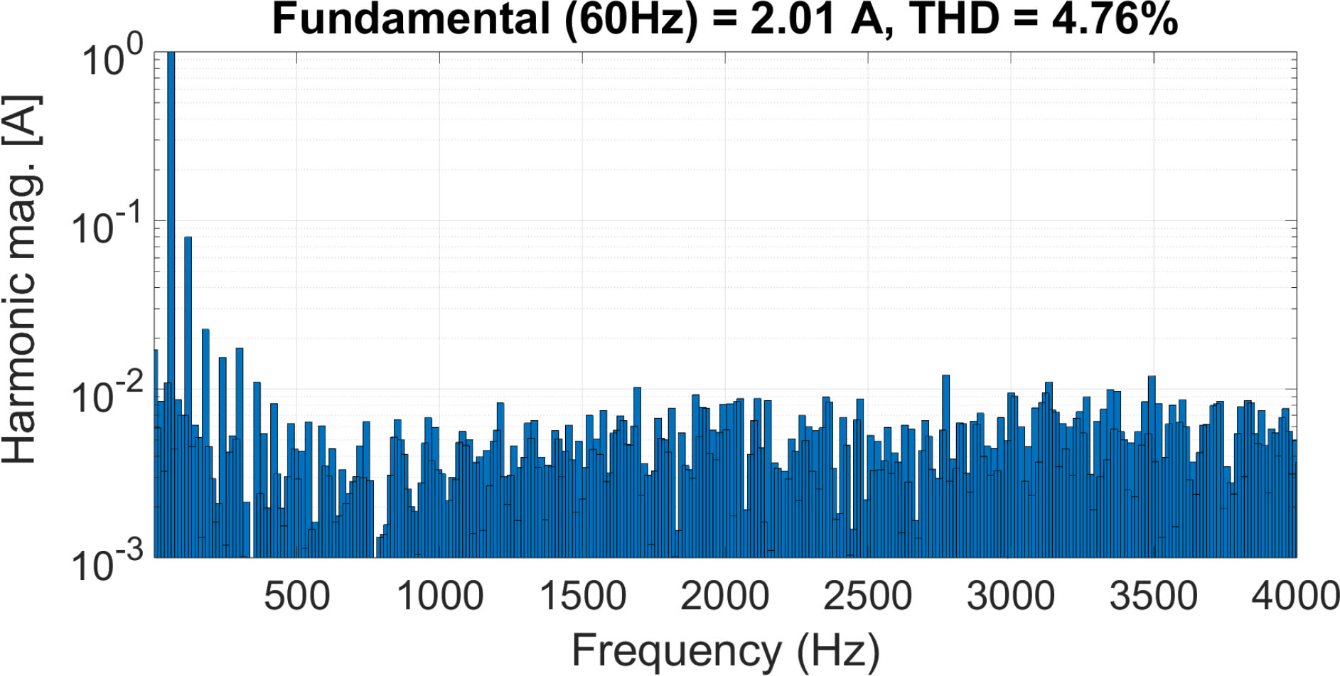
According to the performance comparison between the proposed SMCPI and the repetitive controller, the THD rates obtained under constant current in regular operation, that is, without voltage distortion in the power grid, were analyzed. The graphs used for this analysis are presented in Figures 11 and 12.
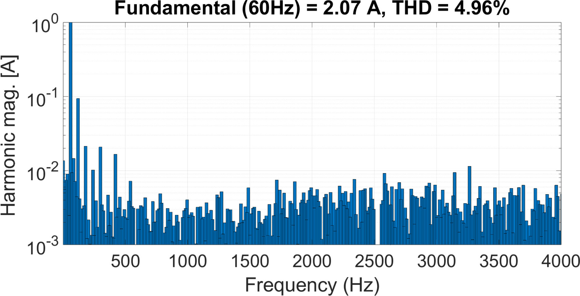
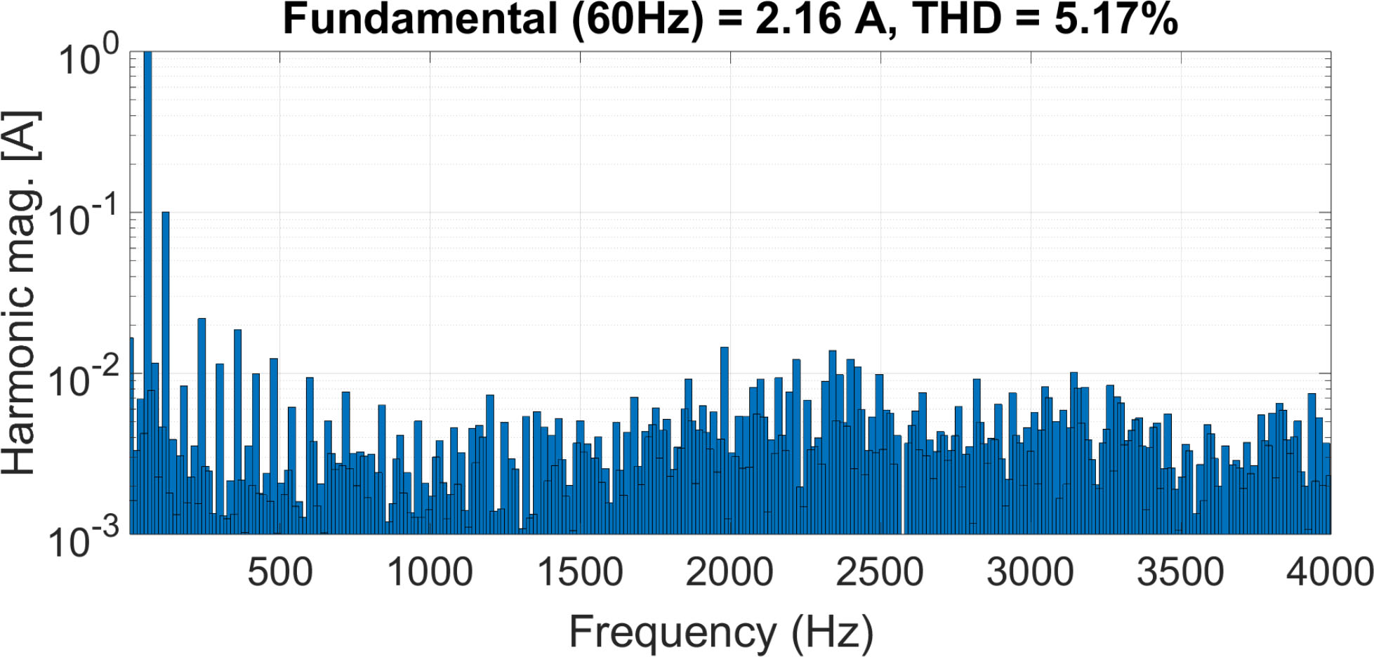
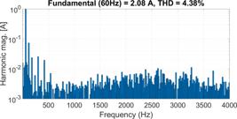
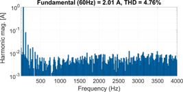
In the test with standard voltage, 9 shows the results obtained with the SMCPI controller, which maintained a THD of 4.38%. In comparison, 10 shows the results of the repetitive driver, which obtained a THD of 4.76%. Both drivers meet the levels required by the standards, which stipulate a maximum harmonic according to [4], [5]. In the distorted voltage condition, the SMCPI driver obtained a THD of 4.96% while the repetitive driver showed a rate of 5.17%. These results show that the SMCPI driver achieves values lower than the limits required by the standards, while the repetitive driver performs slightly lower under the same conditions.
Regarding the current step response time, the SMCPI exhibited better performance, with a settling time of 3.13ms for error correction in the steady state. In contrast, the Repetitive controller had a settling time of 4.32ms.
These times were measured from the step response graph of the current at the output of the single-phase inverter.
This result reinforces that SMCPI is more efficient in correcting THD in a steady state and faster in settling time, indicating a good response in meeting the requested references.
The results presented in Table 3 were prepared to facilitate the comparison between the controllers.
The same experiment evaluated the condition where the power grid presents distorted voltage. The graphs used for this analysis are presented in Figures 15 and 16.
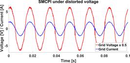
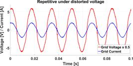
Figure 13 shows the results obtained with the SMCPI, with a THD of 4.96%. On the other hand, Figure 14 shows the results obtained with the repetitive controller, which had a THD rate of 5.17%.
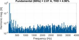
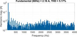
The variation in THD between the value presented by the proposed SMCPI and the Repetitive was 4.23%, a minor percentage difference compared to the result obtained in the test without distorted voltage, which was 8.68%.
Regarding the current step response time, the SMCPI controller exhibited better performance with a response time of 3.82ms, while the Repetitive controller had a response time of 4.19ms. These results are similar to those obtained previously under conditions without distorted voltage. Table 4 presents the obtained results.
D. Computational performance comparison between controllers
The controller's computational performance was evaluated considering the embedded platform used. As discussed in B, the implementation was carried out on a TMS320F28035 DSP operating at 60 MHz without support for floating point operations. This choice highlights the suitability of the proposal for applications with processing capacity restrictions, in which the use of more sophisticated controllers can significantly increase costs, becoming a limiting factor in several projects.
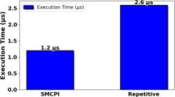
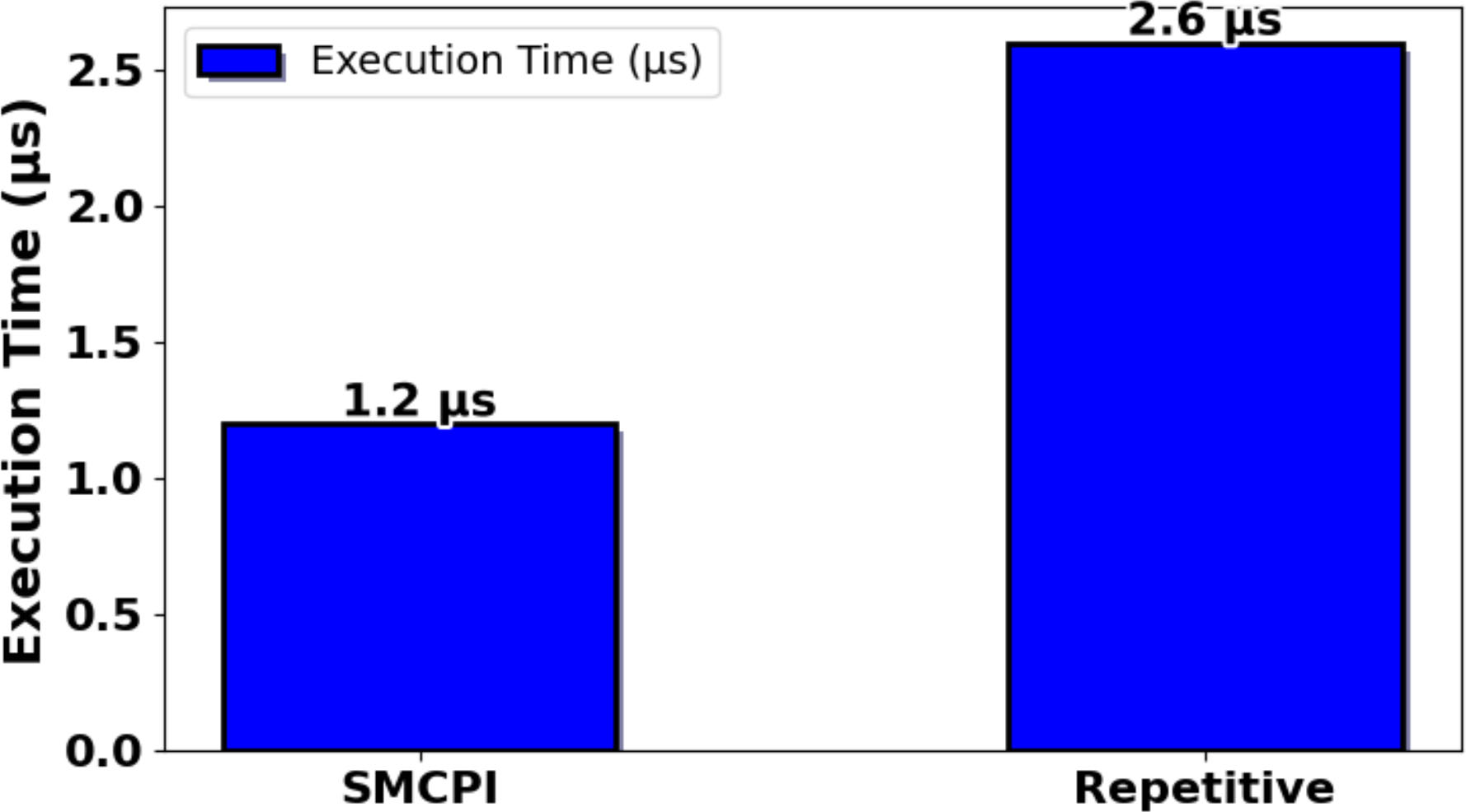
The analysis of the execution time was performed by activating a digital output pin at the beginning of the algorithm's processing cycle and deactivating it at the end of the same cycle. The results show that the SMCPI controller presented an execution time of 1.2 µs, while the repetitive controller required 2.6 µs, as presented in 17. Thus, besides offering better performance in terms of Total Harmonic Distortion (THD) under normal and distortion conditions, the SMCPI exhibited lower computational cost, consuming only 46,15% of the processing time required by the repetitive controller.
VI. CONCLUSIONS
This work presented the application of the SMCPI hybrid controller to control the current of a single-phase inverter connected to the electricity grid. Its ability to reject harmonic distortion, follow the desired current reference, and guarantee system stability was evaluated. The experimental results showed that the SMCPI meets the application's requirements, providing low harmonic content and high energy efficiency.
The tests showed that the controller achieved a THD of 4.38% in a grid without harmonic distortion, with a response time of 3.13ms. In a situation with distorted voltage, the controller showed stable performance, achieving a THD of 4.96% and a response time of 3.83ms. Compared to a commonly used repetitive controller, the SMCPI showed improved efficiency, with an increase of 4.23% in standard grid conditions and 8.68% in distorted voltage situations, meeting current standards.
In addition, the SMCPI facilitated the operation at a constant switching frequency and effectively adapted to fluctuations in grid circumstances. Maintaining system stability despite harmonic disturbances guarantees the reliability and stability of the control system. By integrating sliding mode control with proportional-integral control, the hybrid methodology reduced conventional problems such as vibration while increasing efficient and robust performance and presented a computational cost of only 46.15% compared to the repetitive controller.
The results validate the SMCPI proposal as an effective solution for grid-connected inverters, particularly in applications that require harmonic suppression, resistance to grid disturbances, ease of implementation, and low computational cost. Future work includes the application of three-phase grid-connected inverters and investigating their performance in grids with unusual characteristics like grid impedance variations, further expanding the potential applications in renewable energy systems and power grid infrastructures.
ACKNOWLEDGMENT
The authors thanks the support provided by CNPq (Conselho Nacional de Desenvolvimento Científico e Tecnológico), project 444259/2024-4 and 407867/2022-8. Furthermore, this work was supported by CAPES (Coordenação de Aperfeiçoamento de Pessoal de Nível Superior) - Funding code 001.
-
PLAGIARISM POLICY
This article was submitted to the similarity system provided by Crossref and powered by iThenticate – Similarity Check.
REFERENCES
-
1 J. Jana, H. Saha, K. D. Bhattacharya, “A review of inverter topologies for single-phase grid-connected photovoltaic systems”, Renewable and Sustainable Energy Reviews, vol. 72, pp. 1256–1270, 2017, doi: 10.1016/j.rser.2016.10.049.
» https://doi.org/10.1016/j.rser.2016.10.049 -
2 M. Morey, N. Gupta, M. M. Garg, A. Kumar, “A comprehensive review of grid-connected solar photovoltaic system: Architecture, control, and ancillary services”, Renewable Energy Focus, vol. 45, pp. 307–330, 2023, doi: 10.1016/j.ref.2023.04.009.
» https://doi.org/10.1016/j.ref.2023.04.009 -
3 U. P. Yagnik, M. D. Solanki, “Comparison of L, LC & LCL filter for grid connected converter”, in 2017 International Conference on Trends in Electronics and Informatics (ICEI), pp. 455–458, IEEE, 2017, doi: 10.1109/ICOEI.2017.8300968.
» https://doi.org/10.1109/ICOEI.2017.8300968 - 4 A. J. Sguarezi, Model Predictive Control for Doubly-Fed Induction Generators and Three-Phase Power Converters, ELSEVIER, 2022.
-
5 IEEE, “IEEE Recommended Practice and Requirements for Harmonic Control in Electric Power Systems”, IEEE Std 519-2014 (Revision of IEEE Std 519-1992), pp. 1–29, 2014, doi: 10.1109/IEEESTD.2014.6826459.
» https://doi.org/10.1109/IEEESTD.2014.6826459 -
6 N. F. M. Yusof, D. Ishak, M. Salem, “An Improved Control Strategy for Single-Phase Single-Stage Grid-Tied PV System Based on Incremental Conductance MPPT, Modified PQ Theory, and Hysteresis Current Control”, Engineering Proceedings, vol. 12, no. 1, p. 91, 2022, doi: 10.3390/engproc2021012091.
» https://doi.org/10.3390/engproc2021012091 -
7 N. Singh, S. Jena, C. K. Panigrahi, “A Novel Fuzzy-Sliding Mode control scheme for grid connected single phase VSI”, Materials Today: Proceedings, vol. 57, pp. 2204–2211, 2022, doi: 10.1016/j.matpr.2021.12.289.
» https://doi.org/10.1016/j.matpr.2021.12.289 -
8 M. Balasubramonian, V. Rajamani, “Design and real-time implementation of SHEPWM in single-phase inverter using generalized hopfield neural network”, IEEE transactions on Industrial Electronics, vol. 61, no. 11, pp. 6327–6336, 2014, doi: 10.1109/TIE.2014.2304919.
» https://doi.org/10.1109/TIE.2014.2304919 -
9 C. Xie, D. Liu, K. Li, J. Zou, K. Zhou, J. M. Guerrero, “Passivitybased design of repetitive controller for LCL-type grid-connected inverters suitable for microgrid applications”, IEEE Transactions on Power Electronics, vol. 36, no. 2, pp. 2420–2431, 2020, doi: 10.1109/TPEL.2020.3014365.
» https://doi.org/10.1109/TPEL.2020.3014365 -
10 R. O. Ramírez, J. R. Espinoza, P. E. Melin, M. E. Reyes, E. E. Espinosa, C. Silva, E. Maurelia, “Predictive controller for a threephase/single-phase voltage source converter cell”, IEEE Transactions on Industrial Informatics, vol. 10, no. 3, pp. 1878–1889, 2014, doi: 10.1109/TII.2014.2332062.
» https://doi.org/10.1109/TII.2014.2332062 -
11 H. Komurcugil, S. Biricik, S. Bayhan, Z. Zhang, “Sliding mode control: Overview of its applications in power converters”, IEEE Industrial Electronics Magazine, vol. 15, no. 1, pp. 40–49, 2020, doi: 10.1109/MIE.2020.2986165.
» https://doi.org/10.1109/MIE.2020.2986165 -
12 H. Romdhane, K. Dehri, A. S. Nouri, “Stability analysis of discrete input output second order sliding mode control”, International Journal of Modelling, Identification and Control, vol. 22, no. 2, pp. 159–169, 2014, doi: 10.1504/IJMIC.2014.064291.
» https://doi.org/10.1504/IJMIC.2014.064291 -
13 A. Sufyan, M. Jamil, S. Ghafoor, Q. Awais, H. A. Ahmad, A. A. Khan, H. Abouobaida, “A robust nonlinear sliding mode controller for a three-phase grid-connected inverter with an LCL filter”, Energies, vol. 15, no. 24, p. 9428, 2022, doi: 10.3390/en15249428.
» https://doi.org/10.3390/en15249428 -
14 M. A. E. Alali, Y. B. Shtessel, J.-P. Barbot, S. Di Gennaro, “Sensor effects in LCL-type grid-connected shunt active filters control using higher-order sliding mode control techniques”, Sensors, vol. 22, no. 19, p. 7516, 2022, doi: 10.3390/s22197516.
» https://doi.org/10.3390/s22197516 -
15 M. Huang, H. Li, W. Wu, F. Blaabjerg, “Observer-based sliding mode control to improve stability of three-phase LCL-filtered grid-connected VSIs”, Energies, vol. 12, no. 8, p. 1421, 2019, doi: 10.3390/en12081421.
» https://doi.org/10.3390/en12081421 -
16 M. A. de Brito, E. H. Dourado, L. P. Sampaio, S. A. da Silva, R. C. Garcia, “Sliding mode control for single-phase grid-connected voltage source inverter with l and lcl filters”, Eng, vol. 4, no. 1, pp. 301–316, 2023, doi: 10.3390/eng4010018.
» https://doi.org/10.3390/eng4010018 -
17 M. P. Petronijević, Č. Milosavljević, B. Veselić, S. Huseinbegović, B. Peruničić, “Discrete time quasi-sliding mode-based control of LCL grid inverters”, Facta Universitatis, Series: Electronics and Energetics, vol. 36, no. 1, pp. 133–158, 2023, doi: 10.2298/FUEE2301133P.
» https://doi.org/10.2298/FUEE2301133P -
18 N. B. Lai, K.-H. Kim, “An improved current control strategy for a gridconnected inverter under distorted grid conditions”, Energies, vol. 9, no. 3, p. 190, 2016, doi: 10.3390/en9030190.
» https://doi.org/10.3390/en9030190 -
19 S. Cho, H.-S. Kang, K.-B. Lee, J.-Y. Yoo, “Performance improvement of a grid-connected inverter under distorted grid voltage using a harmonic extractor”, Electronics, vol. 8, no. 9, p. 1038, 2019, doi: 10.3390/electronics8091038.
» https://doi.org/10.3390/electronics8091038 -
20 A. Lunardi, E. Conde, J. Assis, L. Meegahapola, D. A. Fernandes, A. J. Sguarezi Filho, “Repetitive predictive control for current control of grid-connected inverter under distorted voltage conditions”, IEEE Access, vol. 10, pp. 16931–16941, 2022, doi: 10.1109/ACCESS.2022.3147812.
» https://doi.org/10.1109/ACCESS.2022.3147812 -
21 J. Viola, J. Restrepo, J. M. Aller, F. Quizhpi, “Current control for a grid-connected inverter operating with highly distorted grid voltage”, in 2016 IEEE PES Transmission & Distribution Conference and Exposition-Latin America (PES T&D-LA), pp. 1–5, IEEE, 2016, doi: 10.1109/TDC-LA.2016.7805608.
» https://doi.org/10.1109/TDC-LA.2016.7805608 -
22 C. Lascu, I. Boldea, F. Blaabjerg, “Direct torque control of sensorless induction motor drives: a sliding-mode approach”, IEEE Transactions on Industry Applications, vol. 40, no. 2, pp. 582–590, 2004, doi: 10.1109/TIA.2004.824441.
» https://doi.org/10.1109/TIA.2004.824441 -
23 G. M. Vargas-Gil, C. J. C. Colque, A. J. Sguarezi, R. M. Monaro, “Sliding mode plus PI control applied in PV systems control”, in 2017 IEEE 6th International Conference on Renewable Energy Research and Applications (ICRERA), pp. 562–567, IEEE, 2017, doi: 10.1109/ICRERA.2017.8191124.
» https://doi.org/10.1109/ICRERA.2017.8191124 -
24 A. F. B. O. Silva, S. M. Silva, C. H. G. d. Santos, B. d. J. Cardoso Filho, “Aplicação do controle repetitivo a inversor PWM monofásico com filtro LC de sáıda utilizado em fonte programável CA”, Revista Eletrônica de Potência Sobraep, 2013, doi: 10.18618/REP.2013.4.11611169, URL: https://journal.sobraep.org. br/index.php/rep/article/view/444
» https://doi.org/10.18618/REP.2013.4.11611169» https://journal.sobraep.org. br/index.php/rep/article/view/444 -
25 J. P. Bonaldo, J. de Arimatéia Olímpio Filho, A. M. dos Santos Alonso, H. K. M. Paredes, F. P. Marafão, “Modeling and control of a single-phase grid-connected inverter with lcl filter”, IEEE Latin America Transactions, vol. 19, no. 02, pp. 250–259, 2021, doi: 10.1109/TLA.2021.9443067.
» https://doi.org/10.1109/TLA.2021.9443067 -
26 F. Lino, J. Assis, D. A. Fernandes, R. V. Jacomini, F. F. Costa, A. J. Sguarezi, “One-Cycle Fourier Finite Position Set PLL”, MDPI- Energies, vol. 14, no. 7, March 2021, doi: 10.3390/en14071824.
» https://doi.org/10.3390/en14071824 -
27 M. B. Said-Romdhane, M. W. Naouar, I. Slama Belkhodja, E. Monmasson, “An improved LCL filter design in order to ensure stability without damping and despite large grid impedance variations”, Energies, vol. 10, no. 3, p. 336, 2017, doi: 10.3390/en10030336.
» https://doi.org/10.3390/en10030336 -
28 M. Saleem, K.-Y. Choi, R.-Y. Kim, “Resonance damping for an LCL filter type grid-connected inverter with active disturbance rejection control under grid impedance uncertainty”, International Journal of Electrical Power & Energy Systems, vol. 109, pp. 444–454, 2019, doi: 10.1016/j.ijepes.2019.02.004.
» https://doi.org/10.1016/j.ijepes.2019.02.004 -
29 R. A. Fantino, C. A. Busada, J. A. Solsona, “Grid impedance estimation by measuring only the current injected to the grid by a vsi with lcl filter”, IEEE Transactions on Industrial Electronics, vol. 68, no. 3, pp. 1841–1850, 2020, doi: 10.1109/TIE.2020.2973910.
» https://doi.org/10.1109/TIE.2020.2973910 -
30 H. Komurcugil, O. Kukrer, “Investigation of active damping methods for model-based-current-control scheme of single-phase grid-tied VSI with LCL filter”, in IECON 2017-43rd Annual Conference of the IEEE Industrial Electronics Society, pp. 1261–1266, IEEE, 2017, doi: 10.1109/IECON.2017.8216215.
» https://doi.org/10.1109/IECON.2017.8216215 -
31 X. Chen, W. Wu, N. Gao, J. Liu, H. S.-H. Chung, F. Blaabjerg, “Finite control set model predictive control for an LCL-filtered grid-tied inverter with full status estimations under unbalanced grid voltage”, Energies, vol. 12, no. 14, p. 2691, 2019, doi: 10.3390/en12142691.
» https://doi.org/10.3390/en12142691 -
32 M. Cucuzzella, R. Lazzari, S. Trip, S. Rosti, C. Sandroni, A. Ferrara, “Sliding mode voltage control of boost converters in DC microgrids”, Control Engineering Practice, vol. 73, pp. 161–170, 2018, doi: 10.1016/j.conengprac.2018.01.009.
» https://doi.org/10.1016/j.conengprac.2018.01.009 -
33 G. M. Vargas Gil, L. Lima Rodrigues, R. S. Inomoto, A. J. Sguarezi, R. Machado Monaro, “Weighted-PSO applied to tune sliding mode plus PI controller applied to a boost converter in a PV system”, Energies, vol. 12, no. 5, p. 864, 2019, doi: 10.3390/en12050864.
» https://doi.org/10.3390/en12050864 -
34 A. Abrishamifar, A. Ahmad, M. Mohamadian, “Fixed switching frequency sliding mode control for single-phase unipolar inverters”, IEEE Transactions on Power Electronics, vol. 27, no. 5, pp. 2507–2514, 2011, doi: 10.1109/TPEL.2011.2175249.
» https://doi.org/10.1109/TPEL.2011.2175249 -
35 S. Chiang, T. Tai, T. Lee, “Variable structure control of UPS inverters”, IEE Proceedings-Electric Power Applications, vol. 145, no. 6, pp. 559– 567, 1998, doi: 10.1049/ip-epa:19982334.
» https://doi.org/10.1049/ip-epa:19982334 -
36 V. I. Utkin, “Sliding mode control design principles and applications to electric drives”, IEEE transactions on industrial electronics, vol. 40, no. 1, pp. 23–36, 1993, doi: 10.1109/41.184818.
» https://doi.org/10.1109/41.184818 - 37 H. K. Khalil, High-gain observers in nonlinear feedback control, SIAM, 2017.
-
38 J. Jiao, J. Y. Hung, R. Nelms, “Control for a single-phase inverter using a grid current observer”, in IECON 2017-43rd Annual Conference of the IEEE Industrial Electronics Society, pp. 164–170, IEEE, 2017, doi: 10.1109/IECON.2017.8216032.
» https://doi.org/10.1109/IECON.2017.8216032 -
39 M. Bhardwaj, B. Subharmanya, Application Report PV Inverter Design Using Solar Explorer Kit, Texas Instruments, July 2013, URL: https://www.ti.com/lit/an/sprabr4a/sprabr4a.pdf
» https://www.ti.com/lit/an/sprabr4a/sprabr4a.pdf -
40 J. Astrada, C. De Angelo, “Implementation of output impedance in single-phase inverters with repetitive control and droop control”, IET Power Electronics, vol. 13, no. 14, pp. 3138–3145, 2020, doi: 10.1049/iet-pel.2020.0165.
» https://doi.org/10.1049/iet-pel.2020.0165
Edited by
-
Associate Editor
Margarita Norambuena https://orcid.org/0000-0002-2530-2000
-
Editor-in-Chief
Heverton A. Pereira https://orcid.org/0000-0003-0710-7815