Power-Based Control with Feed-forward Disturbance Rejection for Battery-Assisted Quasi-Impedance Source Converter in Photovoltaic Systems
ABSTRACT
This work presents an enhanced power-based control technique for controlling the battery current in a quasi-impedance source converter (qZSC) topology with a feed-forward control loop in order to improve disturbance rejection. Such topology can integrate a photovoltaic array and a battery storage system (BSS) using a single inverter bridge. However, the control strategies for managing the energy stored in the battery for this topology are vulnerable to disturbances in the photovoltaic power and have a high level of complexity, especially in terms of mathematical modeling. Therefore, the proposed control method aims to improve this functionality by implementing a cascade control based on the active power between the qZSC and the grid. Therefore, the dynamic model relating the battery current and the qZSC active power output will be demonstrated, as well as the respective closed-loop controller design. The simulation and control hardware-in-the-loop (C-HIL) results demonstrate the effectiveness of the proposed modeling and control technique.
KEYWORDS
Battery energy storage; photovoltaic generation; power-based control; quasi-impedance source converter
I. INTRODUCTION
In the context of energy transition and global efforts to ensure carbon emission reduction, insertion of photovoltaic (PV) generation sources in electrical systems is constantly increasing. On the other hand, to mitigate the impacts of the PV generation variability on the electrical grid, integration of energy storage systems has been pointed out as a strategic solution, aiming to ensure no impact on the energy management capacity or the stability of the operation, thus contributing to grid reliability and stability [1].
Over the past 20 years, a topology family known as impedance source inverter (ZSI) has been proposed for PV applications, which introduces an impedance network between the DC source and the inverter bridge. The impedance network allows the usage of the short-circuit state in the inverter bridge, which provides an additional voltage boost stage, eliminating the need for a second DC-DC boost converter [2]. The quasi-impedance source converter (qZSC), one of the ZSI variants, has advantages over ZSI for PV applications, including: continuous input current, lower voltage stress on semiconductor devices, and lower operating voltage on the impedance loop capacitor [3]. Furthermore, a battery storage system (BSS) can be integrated with the PV array and the AC grid [4], resulting in the battery-assisted qZSC (BA-qZSC) shown in Fig. 1, which was used for this study.

In such a type of integration, it is necessary to control the energy flow in the BSS, and a typical approach for this topology is to use independent feedback loops to establish both the power transmitted to the grid and the power generated in the PV array [5], [6]. However, such methods may cause low frequency oscillations on the DC side currents and voltages of the BA-qZSC [7]. On the other hand, methods that control directly the battery current were proposed. In [8] the authors implement this feature considering the dynamics of the inverter bridge current to define the gains of the battery current regulator. However, the capacitors of the impedance network and their impacts on the battery current were not fully considered in the modeling. This could result in unexpected dynamic oscillations that threaten the safety and life span of the energy storage components. Thus, the current dynamic regulation method is essential for the dynamic response while ensuring the safety of the system components [9].
In this way, the authors proposed in [10] a direct control of the battery current, applying a power-based approach for the modeling in order to improve stability and simplify the control strategy, considering the Z-source network capacitance dynamics based on a full-order modeling. Although simulation findings show that this technique performs effectively in terms of tracking the battery current reference, it was ineffective in dealing with disturbances induced by oscillations in the PV array's power, with high values for battery current surge and disturbance settling time. Hence, this paper proposes further research to improve the ability of the control method presented in [10] to reject disturbances induced by rapid power fluctuations in photovoltaic generation. Despite the fact that numerous control approaches have been provided in the literature [8]- [10], none of them focuses on addressing the disturbance rejection capability for the BA-qZSC topology, which evidence the originality of the proposed work. Compared to previous control strategies already in the literature, the suggested methodology provides an additional strategy for mitigating the impacts of disturbances in the battery current, hence enhancing the rejection of disturbances in BA-qZSC topology. The main contribution may be highlighted as:
-
Improve the method proposed in [10] by adding a feed-forward loop;
-
Validate the proposed control features with real-time simulation tests;
-
Evaluate the performance of the proposed method in the face of PV power generation, AC load and AC grid voltage disturbances.
The performance of the suggested feed-forward loop is tested using a controller C-HIL configuration. Integrating a physical control hardware device with a simulated plant or environment, C-HIL simulation has emerged as a technique for system design and validation, particularly in automotive, aerospace, and industrial automation, enabling control systems validation without a fully operational physical system, reducing development time, cost, and risk. The C-HIL simulation takes into account important controller implementation parameters, like controller sampling time, which affects control performance and computational load [11], sensor accuracy, which ensures correct control decisions, and hardware limitations, which constrain algorithm complexity and execution time.
The structure of this paper is as follows: Section II describes the complete modeling in the DC side of BA-qZSC, with steady-state and transient analysis. Subsequently, Section III describes the proposed power-based control strategy. Section IV shows the simulation results of the system operating connected to the grid, and finally, Section V presents the overall conclusions of the proposed control method.
II. BATTERY-ASSISTED qZSC AND PV MODELING
A. DC side BA-qZSC modeling
The ZSI principle of operation implies the utilization of one extra switching state compared to the standard eight states (six active and two zero states) of the three-phase voltage source converter (VSC). This extra operational state, Shoot-Through (ST) state, occurs when both switches in at least one phase conduct simultaneously, thus providing a boost capability in the qZSC topology. The equivalent circuits are shown in Fig. 2. During the conventional non-ST states the inverter bridge, viewed from the DC side, is equivalent to a constant current source with value iPN (Fig. 2(a)), whereas in the ST state, the inverter bridge is a short-circuit on the DC side and the switch S7 is blocked (Fig. 2(b)).

Equivalent circuits of the qZSC in DC side: a) Conventional active states; b) Shoot-Through state.
A cycle-averaged dynamic state-space model for the BA-qZSC is obtained assuming that the Z-source network parameters are equal, i.e. , , and , also considering the ST duty ratio and its complement for the non-ST states, in which T is equal to one switching period [9]. This representation can be applied to both steady-state analysis and the dynamic analysis by using (1), where variables iL1, iL2, ib1, uC2 are cycle-averaged values of the inductor/battery currents, and capacitor voltage, respectively:
1) Steady state analysis
In this operating mode, since the derivatives of the cycle-averaged DC-side variables tend to zero, the right-hand side of the system in (1) should also be equal to zero, yielding:
where X and U are the steady-state values of the state-space vector x and the input vector u, respectively. Besides, the battery changes the operation in the main circuitry of the qZSC. According to Fig. 2, as the battery is in parallel with C1, the voltage in this capacitor can be described as , where vb1 is battery voltage, Rb is the internal battery resistance, and ib1 is the battery current. Hence, the current of the battery in steady state is given by
Meanwhile, if the parasitic inductor resistances rL are neglected, the capacitor voltages in steady state VC1 and VC2 are given by
As a consequence, the peak voltage at the DC terminals of the inverter bridge may be described as a function of the steady-state capacitor voltages or of the boost factor B provided by the qZSC topology:
Equations (4) and (5) demonstrate that the DC-side voltages can be controlled by the variable Dst. Lastly, the power balance on the DC side of the qZSC is expressed as
where Pdc is the power in the inverter bridge, PPV is the power generated in PV array, and Pb is the power in the battery.
2) Dynamic small-signal analysis
From the state-space modeling of the qZSC presented in (1), it can be seen that the equations have a nonlinear relation to the Dst control variable, because of its presence in A and B matrices. Furthermore, the system input vector u does not include the variable Dst. To solve these issues, the converter model is linearized for a given operating point [12], considering a small-signal variation in the ST duty-cycle, denoted as . With this, the small-signal model of the BA-qZSC is described as
where the tilde variables indicate the small-signal varying part and
From the results obtained for the modeling, the transfer functions between the state vector variables and the disturbances can be established. To get the transfer function from to the j-th variable (xj) in the state vector , the following relation is used:
where is the transfer function obtained for the variable of interest, Cj is the output line vector for the variable of interest, and I is the identity matrix. It is important to point out that, by using BD, we will only consider the perturbation referring to .
With this, two transfer functions of interest are shown below, as they will be used for the control of the DC side of the BA-qZSC implemented for this work. The first transfer function is for the inductor current ˜iL1 in relation to , named as . Therefore, using (9) and with , one can get
where
and
The second transfer function of interest is for the battery current as a function of denoted as , that may be used to design battery current regulator [8]. Similarly to (10), it is possible to obtain this transfer function by using Cj = [0 0 1 0] and the second of the B matrix, denoted as which is the input vector related to the inverter bridge current iPN . In this way, the transfer function is described as follows:
B. AC side BA-qZSC modeling
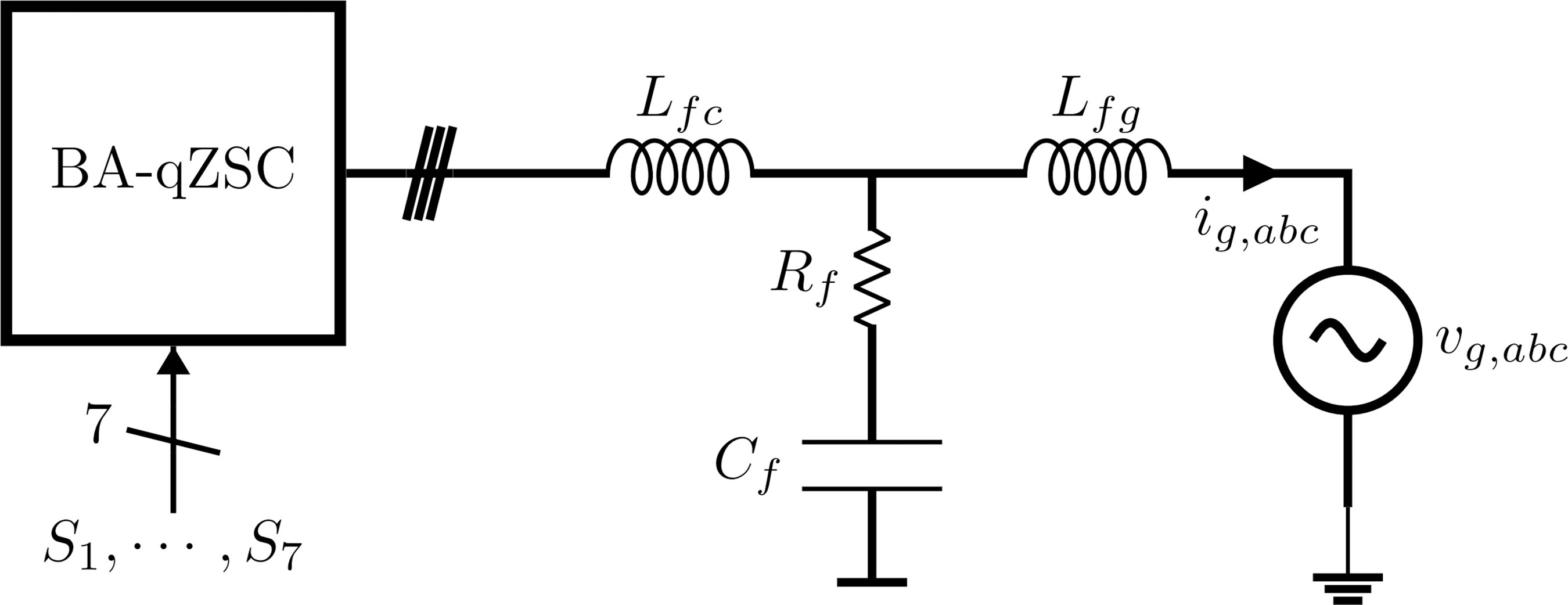
A model for the AC side of the BA-qZSC is also needed, which basically comprises the LCL + R filter on the AC side [13], chosen for the connection with the AC grid as is shown in Fig. 3, and the inverter switching delay related to the switching period T. Since the aim is to control the currents in the filter on the AC grid side (ig,abc), the model considered for the AC current regulation in αβ coordinates is
where

C. PV irradiance dynamics and BA-qZSC parameters
Solar irradiation has a significant impact on the power produced by grid-connected PV systems. As a consequence, this effect is relevant to consider for the battery current regulation in the transient state. According to [14], the PV array power variations should be modeled as a first-order low-pass filter (LPF) function, in which the time constant τPV depends on the PV array dimensions. Hence,
where k corresponds to a constant conversion factor from irradiance to power, in [m²], and EPV is the instantaneous solar irradiance in the PV array. Furthermore, the time constant τPV increases with the area of the PV array, indicating an increase in the variation smoothing effect as the installed power of the PV generation increases. This phenomenon is desirable in view of rejecting power disturbances.
III. PROPOSED CONTROL DESIGN
A. Main control diagram
The main control system must be able to manage the power flow of the PV modules, BSS and AC grid. In order to fulfill these objectives, a global control architecture can be seen in Fig. 4. The control strategy is comprised of two control loops: (i) one linked to dst, which is responsible for controlling the power produced in the PV array by the voltage vPV and the maximum power point tracking (MPPT) algorithm [9], that was designed using the same methodology described in [10]; (ii) the other linked to the modulation index mabc, that implements the conventional current control in the AC side and the battery current control with the proposed feed-forward of pPV in a cascade structure, which gives the active power p* reference, with a null imaginary power q*. The modulation used in this study is the simple boost control (SBC) [15].

B. Grid Current Control Design
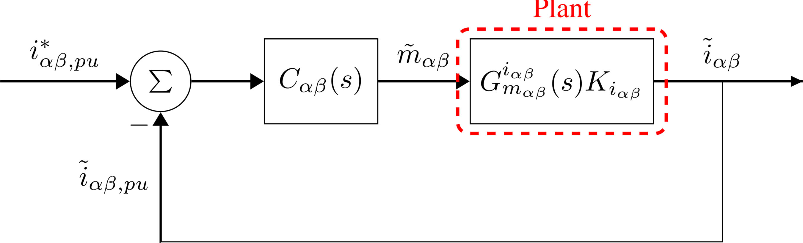
The AC current control loop is designed from the fundamentals of stability in frequency response, where the gains of the continuous-time controller transfer function Cαβ(s) are chosen to establish stability margins in the converter operation. As the controller type chosen is the proportional-resonant (PR), its transfer function is given by
where KP is its proportional gain, KR is the resonant gain, and ω1 is the fundamental angular frequency for 60 Hz. The plant transfer function (15) is the same for both α and β axes, hence the controllers for each axis will be designed identically. The simplified control diagram can be seen in Fig. 5. An additional gain Kiαβ is used in the loop to normalize in p.u. the measurement of the currents. Therefore, as can be seen from the AC current control diagram, the transfer function of the open-loop compensated control system, considering the measurement gain, is expressed as
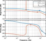
The frequency response of the transfer functions of the plant and the compensated open-loop Tol,αβ(s) can be seen in Fig. 6. The bandwidth of this control loop should be chosen to be at least 10 times smaller than the converter's switching frequency, which in this case is 6250 Hz. Thus, the control gains were chosen to obtain a phase margin of approximately 60° and a crossover frequency fiαβ of 120 Hz, since there is no harmonic compensation in the loop. The gain margin obtained is around 8 dB. Table 1 shows the values obtained for the gains of the PR controllers.
C. Battery Current Control Design
The approach based on the active power in the DC side of the BA-qZSC simplifies the definition of the control plant, since it does not depend on the impedance network parameters as shown in (14). As presented in Fig. 4, the proportional-integral (PI) controller (denoted as Cib(s) in this loop) regulates the battery current ib1 by sending an active power reference p* to the AC current loop. One of the considered loop transfer functions is the closed loop of the AC current control. This transfer function with the output currents in p.u. may be described by the following equation:
It is important to clarify that the active power given as reference for the current control p* corresponds to the power on the DC side pdc of the qZSC if the losses in the inverter bridge are neglected. However, since the internal loop controls the AC current and not directly the power, one must multiply the output Ti(s) by the voltage so that the control output is actually the active power. A simplification adopted in this case is that the closed loop transfer function of the current has dynamics very similar to the active power control loop Gp(s) [16]. Therefore, the following expression may be written:
Besides the AC current closed control loop, it is necessary to establish the mathematical relationship between the reference active power p* given by the battery regulator and the battery current ib1. Therefore, the power flow between the elements on the DC side of the converter must be analyzed. Based on (6), one can obtain the small-signal model, in view of the small variations around an operating point. Thus, considering only the small disturbances and isolating the power in the battery on the left side, one may have
Finally, to obtain the battery current, the right-hand side of (22) is divided by the battery voltage Vb1, which is considered for the control dynamics in question a constant value. Therefore, the final equation for the battery current control project is
1) Proposed disturbance rejection
Equation (23) indicates that power changes in PV array generation provoke a disturbance in the battery current control. However, given that the dynamics of the internal AC current control loop are substantially faster than those of the external loop, it may be assumed that Ti(s) ≈ 1. To reject such a disturbance, the proposed feed-forward loop aims to cancel out the effect of the disturbance, thus adding the computed ppv signal to the control effort of the battery current regulator, as is presented in Fig. 7.

2) Control parameters calculation
The battery current control loop also has a gain Kb for conversion to p.u. system. To compute the battery current control gains, the open loop frequency response specifications were used. For this purpose, it is important to define the open loop transfer function of the battery control Tol,ib(s):
As mentioned before, considering the bandwidth of the inner loop of Ti(s), the bandwidth of the outer loop should be 10 times smaller than the inner loop. In this way, the crossover frequency fib considered for the external loop is 6 Hz, while the desired phase margin ϕb1 is equal to 90°. To meet such criteria, the controller gains Cib(s), besides other relevant parameters, are given in Table 2, where KPb is the proportional gain and KIb is the integral gain of . The diagram presented in Fig. 8 shows the loop shapes before and after the compensation.

IV. CONTROLLER HARDWARE IN THE LOOP RESULTS
The C-HIL testing methodology functions as an intermediary between virtual and experimental testing processes. The rated values and the significant parameters of the studied BA-qZSC are presented in Table 3. The qZSC topology with such parameters was built in Typhoon HIL Control Center®. Fig. 9 details the experimental setup and components to carry out the results. The converter model runs in a Typhoon HIL 602+® and the proposed control strategy was embedded in a LAUNCHXL-28F379D® microcontroller. The tests of the battery current control aim to evaluate the issues of dynamic performance for reference variation and for disturbance rejection of PV power variations.

However, some issues of real-time implementation must be considered. Fig. 10 depicts the implementation scheme configured in Typhoon HIL 602+®. As can be seen, the circuit has been divided into two sub-circuits, each of which is emulated on a separate processing core. The split was made due to the overall computing expense of the real-time models for each element included. The partitioning location was determined using the modeling of the core partitioning element [17]. As a consequence of the information transfer between the cores, this partitioning may lead to latency between simulated sub-circuits in each core. Despite testing the real-world control platform of the power converter, the C-HIL test coverage has limitations. One example is the measuring sensor accuracy, which is emulated by the output channels of the real-time simulator. Therefore, the sensors are not tested together with the controller. Other factors to consider are the simulator's output signal clamping and measurement noise caused by the external connection to the real microcontroller.

A. Reference tracking performance
Fig. 11 shows the dynamic response for a step change of from 0 p.u to 1.0 p.u. In this case, the Typhoon HIL 602+ was set to export the signals with a gain scaling of 4.4 A per Volt in the analog outputs for the AC current channels and 2.2 A per Volt for the battery current channel. The waveforms in the battery current (2 V/div) demonstrate that the controller with the proposed gains in Table 2 can quickly regulate the reference without overshoot. Currents in the AC side (2 V/div) exhibit a similar dynamic behavior. This result agrees with the findings presented in [10].

B. Disturbance rejection performance
1) PV power disturbance: performance and limitations
In order to validate the disturbance rejection performance of the proposed feed-forward controller, a drop in irradiance from 1000 W/m² to 300 W/m² at t = 0.0 s was imposed in the PV array. The effects of this variation are depicted in Fig. 12.

Disturbance rejection comparison considering τPV = 0.01 s. The trigger event occurs at t = 0 s.
In this scenario, the output data of the experiment was exported and plotted with the software MATLAB®. The graph of the converter input current iL1(t) shows the dynamics of the expected irradiance variation, according to (17). Furthermore, the disturbance rejection capability in the battery current ib1(t) can be validated by inserting identical disturbances for both cases, with and without feed-forward control, as illustrated by the curves presented in Fig. 12.
It can be noticed that the feed-forward loop reduces the disturbance in the battery current. As can be observed, without the suggested disturbance rejection, the battery current reaches a maximum of around 10 A, whereas with disturbance rejection, the highest value is around 4 A.
The proposed control was also evaluated while disregarding the inherent dynamics of environmental variations in the PV array. In mathematical terms, τpv = 0. As a result, a step-type disturbance was used to simulate an instantaneous change in the generated power, which represents the shutdown of an area of the PV modules via protection devices. In this situation, it is possible to draw attention to the dynamic constraints of the proposed control method, since the disturbance becomes more critical. The results obtained for the instantaneous variation mentioned are displayed in Fig. 13. It is visible that the battery current reached higher levels during the disturbance. On the other hand, the transient is put out faster than is shown in Fig 12. Nevertheless, it is noticeable that the feed-forward control approach contributes to reducing the battery current's maximum value.

To summarize the results and quantify the contribution of the proposed control, two quantities were measured: the maximum absolute value of the amplitude of battery current due to the disturbance, denoted by , and the time in which the current returns to between -0.075 p.u. and 0.075 p.u. after the disturbance, denoted by ts. The criteria for the ts battery current amplitude values were established considering the battery current ripple, which is 0.05 p.u. in the operating test point. Table 4 displays the results obtained for and ts in Fig. 12 and Fig. 13. The proposed feed-forward control loop was able to significantly mitigate the impact of the generated PV power disturbance, even when its dynamics were ignored.
2) AC Load disturbance
The load variation test was performed by connecting a load with a unity power factor to the AC side of the converter. This load has a a nominal power consumption of 12 kW, which corresponds to the PV array's peak power. Then, the load power consumption is instantaneously reduced to half the maximum generating power (6 kW), simulating the turn-off of a portion of the load on the AC side. The results found for this disturbance are shown in Fig. 14.

The variables ia, ib and ic represent the output AC currents provided by the qZSC, whereas iga, igb, and igc are the three phase AC grid currents. Despite the significant variance produced by the AC demand, the battery current remained constant. This implies that the proposed control is unaffected by this disturbance. It is worth noting that the response to this type of disruption was the same with and without the feed-forward loop.
3) AC grid voltage disturbance
Finally, the behavior of the proposed control in the face of disturbances in the AC grid voltage to which the converter is connected was evaluated. The effects observed on the converter's AC output currents and the battery current due to this disturbance are shown in Fig. 15. In this case, a fifth harmonic with an amplitude equal to 5 % of the nominal voltage value was added to the fundamental voltage component in each phase.

Battery current disturbance due to 5% of the nominal amplitude of the fifth harmonic distortion in the AC grid voltage.
It is evident that the converter's AC side currents acquire a low-frequency harmonic content, resulting in a 8.90 % of total harmonic distortion (THD). Furthermore, as predicted by the instantaneous power theory [18], the AC grid distortion results in disturbances in the battery current at 360 Hz. Nevertheless, the small size of these disturbances indicates that the battery current is not sensitive to harmonic distortion. In particular, the harmonic distortion of the AC grid caused an additional 0.84 A ripple in the battery current in the sixth harmonic while the ripple without distorted AC grid voltage is 1.0 A.
V. CONCLUSION
In this work, a feed-forward loop strategy has been proposed for a power-based control method of battery current control in the BA-qZSC topology. The C-HIL results validate the proposed disturbance rejection mechanism, as the impacts of variation have been dampened by the feed-forward control loop of power in the PV array. The control performance in the reference tracking of the battery current regulator was also demonstrated. Furthermore, the control approach can be employed in situations where there is periodic change in PV active power, such as in implementations with the Perturb and Observe (P&O) MPPT algorithm.
The reported results indicate that a validation using more realistic oscillations in PV generation would be appropriate to verify the operation of the proposed control technique. Further study could thus be conducted in the context of developing an experimental prototype to evaluate the results discovered in C-HIL in practice. It is also possible to use the control strategy proposed for the BA-qZSC topology for other alternative energy sources that have intrinsic variations in their operation and can be connected to the DC side of the converter. Lastly, in higher power systems, the control method is similar and may be implemented by recalculating the controller gains, but with the advantage of raising the time constant τpv, which results in intrinsically smoother PV power fluctuations.
ACKNOWLEDGMENT
This study was financed in part by the Coordenação de Aperfeiçoamento de Pessoal de Nível Superior - Brasil (CAPES) Finance Code 001. This work was developed under the Research, Development and Innovation Program in Priority Areas for the National Electricity Sector #401424/2023-5: "Development of a new solar photovoltaic generation system with integrated energy storage, controlled and connected to the electrical grid through a single static power converter for smoothing power variations in the grid.", promoted by Conselho Nacional de Desenvolvimento Científico e Tecnológico (CNPq).
-
PLAGIARISM POLICY
This article was submitted to the similarity system provided by Crossref and powered by iThenticate – Similarity Check.
REFERENCES
-
1 R. M. de Souza, F. J. P. Ferreira, A. S. Neto, R. C. Neto, F. A. S. Neves, J. F. C. Castro, “An Analysis of the Limitations of Power Smoothing Metrics and Future Perspectives for Their Evolution in the Context of BESS-Based Systems”, Eletrônica de Potência, vol. 29, p. e202423, Aug. 2024, doi: 10.18618/REP.2005.2.017021, Available in: https://journal.sobraep.org.br/index.php/rep/article/view/933
» https://doi.org/10.18618/REP.2005.2.017021» https://journal.sobraep.org.br/index.php/rep/article/view/933 -
2 Fang Zheng Peng, “Z-source inverter”, IEEE Transactions on Industry Applications, vol. 39, no. 2, pp. 504–510, 2003, doi: 10.1109/TIA.2003.808920.
» https://doi.org/10.1109/TIA.2003.808920 -
3 J. Anderson, F. Peng, “Four quasi-Z-Source inverters”, in 2008 IEEE Power Electronics Specialists Conference, pp. 2743–2749, June 2008, doi: 10.1109/PESC.2008.4592360.
» https://doi.org/10.1109/PESC.2008.4592360 -
4 M. M. Haque, P. J. Wolfs, S. Alahakoon, M. A. Islam, M. Nadarajah, F. Zare, O. Farrok, “Three-Port Converters for Energy Conversion of PV-BES Integrated Systems—A Review”, IEEE Access, vol. 11, pp. 6551–6573, 2023, doi: 10.1109/ACCESS.2023.3235924.
» https://doi.org/10.1109/ACCESS.2023.3235924 -
5 B. Ge, H. Abu-Rub, F. Z. Peng, Q. Lei, A. T. De Almeida, F. J. Ferreira, D. Sun, Y. Liu, “An energy-stored quasi-Z-source inverter for application to photovoltaic power system”, IEEE Transactions on Industrial Electronics, vol. 60, no. 10, pp. 4468–4481, 2013, doi: 10.1109/TIE.2012.2217711.
» https://doi.org/10.1109/TIE.2012.2217711 -
6 S. Agrawal, B. Tyagi, V. Kumar, P. Sharma, “Digital Controller Design and Implementation for AC and DC Side of 3ph qZSI”, IEEE Transactions on Industry Applications, vol. 60, no. 1, pp. 672–683, 2024, doi: 10.1109/TIA.2023.3320120.
» https://doi.org/10.1109/TIA.2023.3320120 -
7 A. Lashab, D. Sera, J. Martins, J. M. Guerrero, “Model PredictiveBased Direct Battery Control in PV Fed Quasi Z-Source Inverters”, in 2018 5th International Symposium on EnvironmentFriendly Energies and Applications (EFEA), pp. 1–6, IEEE, 9 2018, doi: 10.1109/EFEA.2018.8617084.
» https://doi.org/10.1109/EFEA.2018.8617084 -
8 J. Khajesalehi, K. Sheshyekani, M. Hamzeh, E. Afjei, “Highperformance hybrid photovoltaic -battery system based on quasi-Zsource inverter: Application in microgrids”, IET Generation, Transmission and Distribution, vol. 9, no. 10, pp. 895–902, 2015, doi: 10.1049/iet-gtd.2014.0336.
» https://doi.org/10.1049/iet-gtd.2014.0336 -
9 S. Hu, Z. Liang, X. He, “Research on the Dynamic Characteristics and Regulation Method of the Energy Stored Quasi-Z-Source Inverter System”, IEEE Transactions on Industrial Electronics, vol. 67, no. 6, pp. 4590–4599, 2020, doi: 10.1109/TIE.2019.2931244.
» https://doi.org/10.1109/TIE.2019.2931244 -
10 M. S. Neves, L. G. B. Rolim, “A Power-Based Control Approach for a Battery-Assisted Quasi-Impedance-Source Converter Applied in Photovoltaic Systems”, in 2023 IEEE 8th Southern Power Electronics Conference and 17th Brazilian Power Electronics Conference (SPEC/COBEP), pp. 1–8, 2023, doi: 10.1109/SPEC56436.2023.10407363.
» https://doi.org/10.1109/SPEC56436.2023.10407363 -
11 S. Xia, J. Xu, L. Guo, S. Li, H. Guo, “Real-Time Modeling Method for Large-Scale Photovoltaic Power Stations Using Nested Fast and Simultaneous Solution”, IEEE Transactions on Industrial Electronics, vol. 72, no. 3, pp. 2679–2689, 2025, doi: 10.1109/TIE.2024.3440469.
» https://doi.org/10.1109/TIE.2024.3440469 -
12 W. Liu, Y. Pan, Y. Yang, “Small-Signal Modeling and Dynamic Analysis of the Quasi-Z-Source Converter”, in IECON 2019 45th Annual Conference of the IEEE Industrial Electronics Society, pp. 5039– 5044, IEEE, oct 2019, doi: 10.1109/IECON.2019.8927359, Available in: https://ieeexplore.ieee.org/document/8927359/
» https://doi.org/10.1109/IECON.2019.8927359» https://ieeexplore.ieee.org/document/8927359/ -
13 B. Mondal, A. K. B, “Analysis of Inverter Output Current Ripple and Design of Inverter-Side Output Filter Inductor for Grid-Connected Applications”, IEEE Transactions on Industry Applications, vol. 61, no. 1, pp. 686–702, 2025, doi: 10.1109/TIA.2024.3481396.
» https://doi.org/10.1109/TIA.2024.3481396 -
14 M. Wicke, T. Bocklisch, “Hierarchical Energy Management of Hybrid Battery Storage Systems for PV Capacity Firming and Spot Market Trading Considering Degradation Costs”, IEEE Access, vol. 12, pp. 52669–52686, 2024, doi: 10.1109/ACCESS.2024.3387748.
» https://doi.org/10.1109/ACCESS.2024.3387748 -
15 J. Mascarenhas, M. d. S. Neves, B. Figueiredo, L. G. B. Rolim, “Implementation of Simple Boost Control Pulse Width Modulation for a Two-Level Three-Phase Quasi-Impedance Source Converter”, in XXV Congresso Brasileiro de Automática, Oct 2024, Available in: https://www.sba.org.br/cba2024/papers/paper 5490.pdf
» https://www.sba.org.br/cba2024/papers/paper 5490.pdf -
16 J. Liu, Y. Xia, W. Wei, Q. Feng, P. Yang, “Effect of Control Damping on Small-Signal Stability of Grid-Forming VSCs Considering Interaction Between Inner and Outer Loops”, IEEE Transactions on Power Electronics, vol. 39, no. 6, pp. 7685–7695, 2024, doi: 10.1109/TPEL.2024.3381148.
» https://doi.org/10.1109/TPEL.2024.3381148 -
17“Core couplings Ideal Transformer — typhoon-hil.com”, https://www.typhoon-hil.com/documentation/typhoon-hil-softwaremanual/References/core couplings IT.html, [Accessed 04-03-2025].
» https://www.typhoon-hil.com/documentation/typhoon-hil-softwaremanual/References/core couplings IT.html - 18 H. Akagi, E. H. Watanabe, M. Aredes, Instantaneous power theory and applications to power conditioning, John Wiley & Sons, 2017.
Edited by
-
Editor-in-Chief
Heverton A. Pereira https://orcid.org/0000-0003-0710-7815
-
Associate Editor
Muhammad U. Mutarraf https://orcid.org/0000-0001-7245-2231