Automatic Power Flow Control Strategy in Hybrid Microgrids: Development and Validation using Controller Hardware-in-the-Loop
ABSTRACT
Research on hybrid microgrids has attracted significant interest mainly due to the advantages that this topology offers compared to a solely direct current (DC) or alternating current (AC) microgrid. Among these advantages, one of the most frequently mentioned is the increased system reliability, due to the possibility of operating in either islanded mode or grid-connected mode, depending on the need. Additionally, the ability to export power to the AC grid is a valuable application of this type of system. In this context, this paper proposes a new control and management strategy for a hybrid microgrid. The analyzed microgrid consists of a photovoltaic system, energy storage systems, and an emergency power source, as well as DC and AC loads. The interface with the AC side is achieved through an inverter, and the microgrid may or may not be connected to the external grid. The proposed strategy emphasizes the management of all subsystems, as well as the control of operations in both grid-connected and islanded modes. The system was implemented using Controller Hardware-in-the-Loop (C-HIL). The results demonstrated that the proposed strategy enabled effective microgrid management, particularly regarding the proper coordination of the batteries through SOC equalization and the maintenance of each operational state of the microgrid.
KEYWORDS
Bidirectional power flow; Distributed power generation; Hardware-in-the-Loop; Microgrid; Power system management
I. INTRODUCTION
Smart Grids have gained significant popularity in recent years as they address society's need for a more sustainable and efficient energy distribution [1]-[7]. These grids aim to integrate communication and information technologies with traditional electrical infrastructure to enable more efficient management of energy consumption and production [7,8].
Microgrids are an emerging technology within smart grids, working as energy distribution systems capable of operating with a variety of energy sources, including solar panels, wind turbines, and batteries. They provide a more efficient and reliable alternative for energy distribution in remote areas or locations where the traditional power grid is unavailable [9]-[15].
Microgrids can be intelligently managed using energy management and control algorithms [3],[5],[16]. These algorithms can optimize the use of renewable energy sources, reduce operational costs, and enhance the quality of energy supply. Furthermore, they can be integrated into larger smart grids to enable more efficient and sustainable management of electrical energy consumption and generation [14]-[18].
In this scenario, research on smart electrical grids and microgrids is crucial for developing innovative solutions for electrical energy distribution. Alternating current (AC) or direct current (DC) systems, each one of them, have their advantages. To make the most of them, it is interesting to integrate these technologies into hybrid microgrids. However, coexistence and cooperation among them are complex, due to their particularities [19], [20]. Additionally, the simultaneous operation of very distinct technologies increases the difficulty. Therefore, a management system is a critical part of the conception and implementation of hybrid microgrids, so research in this area follows different paths to reach good results [21]-[23]. Due to the multiplicity and diversity of microgrids, proposals have been presented commonly in the literature for particular cases, without prejudice to the generalization of controllers. Some authors even implement complex devices with applications using solid-state transformers to perform management, power flow coordination, and DC bus regulation [24].
In [25], the developed management strategy is analyzed for a specific microgrid with renewable sources and a diesel generator, the latter operating only in critical situations. A single bidirectional converter is connected to all the power units. In [26], a management system for a hybrid microgrid containing photovoltaic modules and a wind turbine, called primary sources, batteries, and fuel cells is approached. The primary sources are not part of the management, as they operate at their maximum power points. The authors claim that they achieve optimal conditions and lower costs by addressing the system only at power and energy levels. Despite this, considerations regarding the intrinsic operation of the units and converters with their respective controls for voltage regulation, paralleling, etc., are lacking. In [27], simplified control strategies are presented for hybrid microgrids operation. The voltage and current regulations are obtained without the need for complex control schemes, and the effectiveness of the proposed methodology is validated using the Matlab/Simulink platform.
While acknowledging the importance of the results achieved by the authors in the aforementioned works, it is important to emphasize that any method must take into account the inherent difficulty in the interaction between technological systems with distinct behaviors.
At the DC side, the exigence falls on power sharing and equilibrium considering variable and intermittent operation of renewable sources, such as photovoltaic systems, and battery energy systems dynamics, with frequent alterations between charge and discharge profiles depending on local load behavior. All of this in a system that must maintain DC bus voltage regulated for satisfactory operation. Therefore, there is a need for advanced controls and the use of DC-DC converters, even more so in the context of hybrid microgrids [9], [28], [29].
On the AC side, techniques for connecting microgrids to the grid and seamless transition have been extensively reviewed in [30]. The difficulty in controlling power flow in connected mode and achieving an effective seamless transition is evident. These points are even more sensitive when dealing with hybrid microgrids. In fact, according to [31], there are few solutions for hybrid microgrids with seamless transition.
Most studies on hybrid microgrids, as can be seen in this state-of-the-art review presented in [31], are divided. Some only address energy management without explaining the controllers themselves, considering operational details such as voltage and frequency regulation, load balancing, etc. Others develop controllers without clearly defining optimal management. On the other hand, some fail to utilize the best control and management techniques simultaneously to achieve reliability, flexibility, robustness, and high quality. Complexity is another issue. Furthermore, literature still lacks studies that prove the effectiveness of complex energy management systems in hybrid microgrids on real-time simulation platforms to support system operation [32]-[42].
In light of the foregoing, considering that hybrid microgrids are fundamental systems in the advancement of modern power elements and smart grids, but configure complex systems in operation and control, this paper proposes an innovative power flow management strategy, unifying different technologies and preserving electrical energy generation and consumption with high quality, efficiency, flexibility and reliability levels. The proposed approach combines DC and AC areas, including photovoltaic systems, BESS, dispatchable generators, electronic DC load, AC load and external power system access. The integration is achieved through power electronics converters.
In the DC side, following the technique developed in [43], DC-DC converters are capable of both maintaining the batteries in a balanced charging state and power sharing, and allowing optimized production by the photovoltaic modules. All this while maintaining steady DC voltage bus regulation.
The link between the DC and AC sides, as well as the operation of the latter side itself, is made by an inverter. This converter guarantees islanding and grid connection with seamless transition, with adjustments for power exchanges between the external system with the AC load and the DC elements. This applied control method was already presented by the authors in [44] with good results for AC microgrids.
In this new work, the strategy developed by the authors in [43] and [44] also proves satisfactory for hybrid microgrids, and the proposed energy flow management consolidates this broad and complex range of devices working simultaneously. It defines parameters and conditions for a hybrid microgrid’s complete operation, and its architecture, although previously defined, is vast due to the multiplicity of its components. The system follows a unique organization that is capable of, without human supervision, regulating the DC bus voltage, equalizing the state of charge (SoCs) of the batteries in energy storage systems, extracting maximum power from the photovoltaic system, allowing smooth transitions between islanded and grid-connected operation modes, controlling the inverter's output frequency, and ensuring that both DC and AC loads are continuously supplied. The Typhoon HIL 404 real-time simulator was used to simulate the hybrid microgrid and to provide a communication interface with the Texas Instruments TMS320F28379D Digital Signal Processor (DSP), used to embed the algorithm for energy flow control and management.
Considering the excellent results presented in this new work, the energy management strategy developed proves to be an important contribution to the field, leveraging progress in the study, research, and development of hybrid microgrids.
II. MIGROGRID SETUP
The hybrid microgrid implemented and simulated in real time is presented in Figure 1.

It is composed of two Battery Energy Storage Systems (BESS 1 and BESS 2) with a nominal power of 5 kW and battery charge and discharge control via bidirectional DC-DC Buck-Boost converters; a Photovoltaic System with a maximum power of 7.7 kW and MPPT control via a DC-DC Boost converter; an Inverter with a nominal power management of 5 kW; a 2.5 kW DC Electronic Load; and a 2.5 kW AC Load.
Additionally, an Emergency Auxiliary DC Power Supply, which can be formed by a fuel cell system with a DC-DC converter or a diesel generator with an AC-DC converter, is connected to the DC bus. It is activated only when the photovoltaic system cannot supply the loads during islanded operation mode.
III. IMPLEMENTATION OF THE HYBRID MICROGRID ON THE HIL PLATFORM
Figure 2 presents the supervisory interface of the microgrid scheme implemented in the Typhoon HIL Control Center software. The supervisory interface displays readings of power, current, and voltage related to the operation of the BESSs, the inverter, the Photovoltaic System, and the DC and AC Loads. It also shows the waveform of the voltages and currents of the AC Grid and the Inverter output, as well as the waveform of the DC bus voltage and the current of the AC Load. Furthermore, it displays information about the energization flags, Fe, for management in Connected Mode, Fc, and for management in Islanded Mode, Fi, whose operations will be detailed in Section 5.

Supervisory Interface of the Microgrid Implemented in SCADA within Typhoon HIL Control Center Software
IV. CONTROL STRATEGIES OF THE HYBRID MICROGRID CONVERTERS
In this section, the control strategies for the power electronic converters involved in the energy management of the Hybrid Microgrid will be detailed. Among the converters that make up the microgrid, the following stand out:
-
The bidirectional DC-DC Buck-Boost converters, designed for battery charge and discharge control and for imposing the DC bus voltage;
-
The inverter, designated for managing the power flow between the DC and AC sides of the microgrid; and
-
The DC-DC Boost converter, responsible for controlling the extraction of power from the photovoltaic system.
A. CONTROL STRATEGIES OF THE BIDIRECTIONAL BUCK-BOOST DC-DC CONVERTERS
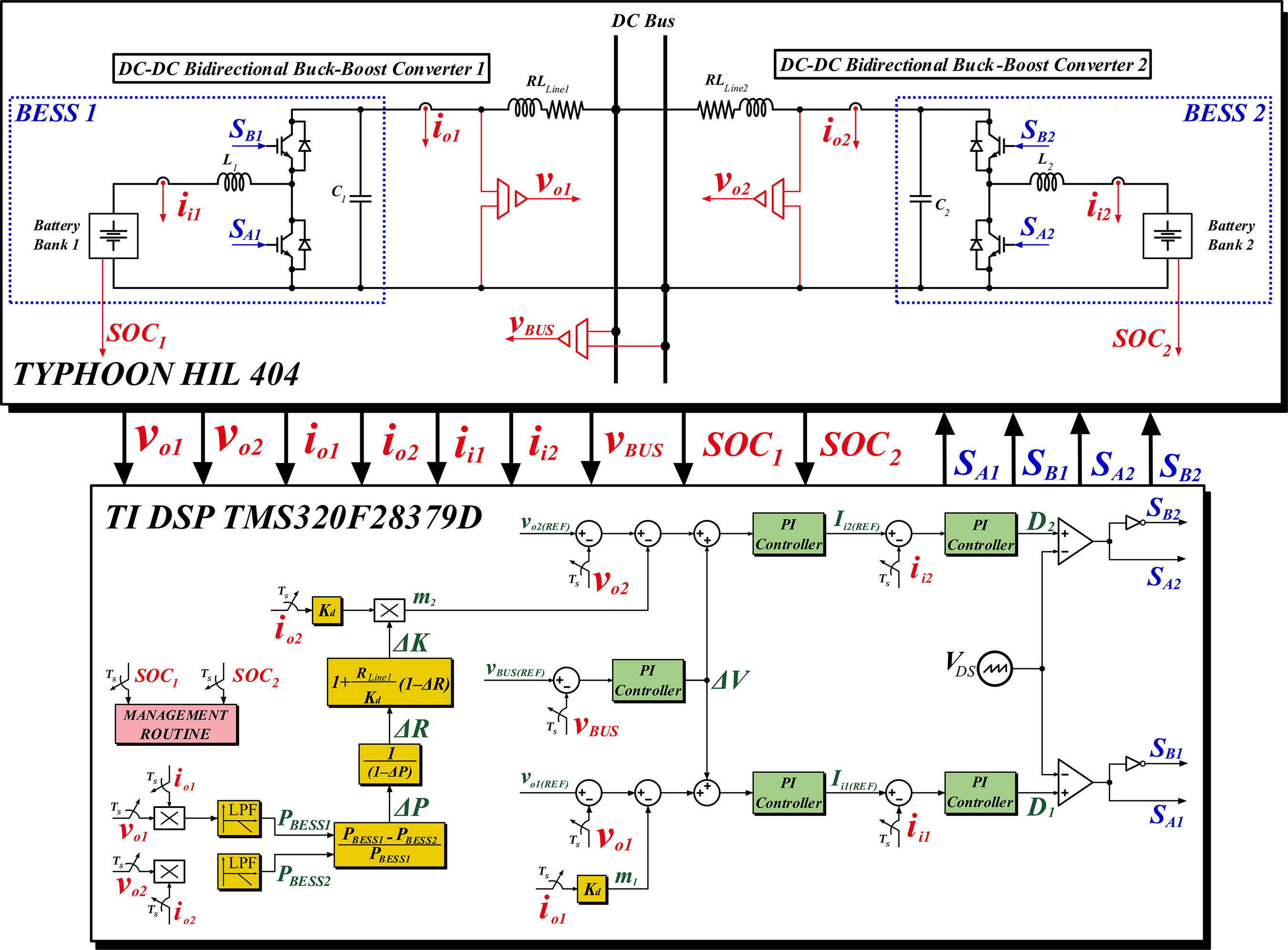
Figure 3 demonstrates the control strategies defined for the bidirectional DC-DC Buck-Boost converters that operate in BESS 1 and BESS 2. For the control strategies to function, it is necessary to acquire signals for the output voltages (vo1 and vo2), output currents (io1 and io2), and input currents (ii1 and ii2) of BESS 1 and BESS 2, as well as the signal for the DC bus voltage (vBUS). The signals for the battery state of charge (SOC1 and SOC2) are collected solely for use in the power flow management routine of the microgrid, as will be detailed in Section 5.

The traditional DC droop control is applied to the control strategy of BESS 1, which defines the pulse signals SA1 and SB1 for the bidirectional DC-DC converter 1. As is common for DC systems, the DC droop gain, Kd , can be calculated by (1), where ΔVo is the percentual voltage oscillation, and ΔIo represents the current of the DC-DC converter, considering the nominal output current.
In the proposed system, both bidirectional DC-DC converters operate simultaneously, serving as grid-forming units and managing the charge and discharge of the battery banks within an internal control loop. Since the output voltages of the BESS are controlled, the simplified system can be represented as a voltage source for each unit, along with the line resistances shown in Figure 4.
Through zero-level control (internal loops), the considerations related to expressions (2) and (3) are possible, where RLine1 is the line resistance of bidirectional DC-DC converter 1; RLine2 is the line resistance of bidirectional DC-DC converter 2; and ΔR is the variation in line resistance.
The power imbalance (ΔPo) between the grid-forming units can be calculated as:
Thus, since real-time monitoring of power imbalance is possible, the line resistance variation can be determined by reformulating (4) as (5).
The output power and the output voltages for each converter are now defined by expressions (6) to (9), where Kd1 and Kd2 are the DC droop gains, calculated by (1), for bidirectional DC-DC converters.
Hence:
The zero-level control and the design of the DC droop control then define:
Therefore, the power imbalance, given by (10), can be rewritten as (14).
As a result, the power imbalance in (14) remains unaffected by the voltage measured at the bus. With real-time measurements of ΔPo the adjustment of the DC droop coefficient, ΔK, can be derived based on the steady-state power imbalance.
To resolve the power discrepancies between the converters, ΔPo is adjusted to zero. As a result, the adjustment ΔK can be expressed by (16).
Thus, expression (16) is used to calculate the adjustment ΔK to apply to the DC droop control strategy of BESS 2, which defines the pulse signals SA2 and SB2 of bidirectional DC-DC converter 2, thereby eliminating the power imbalance between the BESS units. A detailed analysis on the evaluation of adaptive droop control for steady-state power balancing in DC Microgrids using C-HIL can be found in [43].
B. CONTROL STRATEGY OF THE INVERTER
Figure 4 illustrates the inverter control strategy. The inverter is connected to the DC bus and operates as an interface converter between the DC and AC buses of the hybrid microgrid, managing power flow between them and integrating with the energy management system.

The three-phase inverter unit features a conventional bridge topology with six semiconductor switches. At its output, an LC filter is integrated. The AC load is of the RL type, with the possibility of an increase in its value due to a parallel load of the same type. Between the filter and the AC load, there is an RL impedance typical of distribution networks, as well as an additional inductor. The external AC grid can be connected to the hybrid microgrid through a static interconnection switch. This load also has a line with series RL impedance.
For the control strategy to operate, it is necessary to acquire the following signals: the inverter output voltages (voA-INV, voB-INV and voC-INV ), the inverter output currents (ioA-INV, ioB-INV e ioC-INV), the voltages at the AC load (vLoadA, vLoadB e vLoadC the currents at the AC load (iLoadA, iLoadB e iLoadC the phase A voltage of the AC grid (vGridA), and the DC bus voltage (vBUS).
The controllers operate in the stationary αβ reference frame. Therefore, an ABC-αβ transformation is applied to the phase voltages and currents of the inverter (via the LC filter). The resulting signals, Voα-INV, Ioα-INV, Voβ-INV and Ioβ-INV, are used to calculate the instantaneous powers pINV and qINV through (17) and (18). The average values of the three-phase active and reactive powers, PINV and QINV, respectively, are determined by subjecting the instantaneous powers to a low-pass filter.
Using the calculated powers, the inverter control strategy is established, enabling operations in islanded mode, smooth transitions, active synchronization, connection to the external AC grid, and power flow control. This strategy is based on the conventional droop control method, represented by equations (19) and (20), where ω0 is the nominal constant frequency, E0 is the voltage amplitude equivalent, kdp and kdq are the droop constants, and P0 and Q0 are the reference powers for when PINV = P0, QINV = Q0, ωINV = ω0 and EINV = E0. This technique enables power sharing on the AC side and generates voltage and frequency references.
For the active synchronization and smooth transition stage with the external AC grid, a classic PLL (Phase Locked Loop) structure is employed. In this structure, the product of the phase A voltage of the inverter and the phase A voltage of the AC grid, shifted by 90°, is subjected to the actions of a PI controller and a low-pass filter. The final result is the derivation of a frequency correction signal, ∆ω, which is added to the droop equations during the transition stage. This ensures synchronization in both frequency and phase. For voltage amplitude, the value of ∆E is obtained from the difference between the amplitudes of the grid and inverter voltages. Consequently, the relations representing the droop equations are modified as follows:
Once synchronization and the transition are completed, the inverter system begins operating in grid-connected mode. In this mode, the inverter's power outputs can be freely controlled by adjusting the active and reactive power references, PINV(REF) and QINV(REF) respectively. Using these references, the management routine determines the desired energy flow characteristics. To achieve this, the droop equations are modified once again, with the values of ω0 and E0 replaced by ωGRID e EGRID, respectively, which are provided by a SOGI-PLL coupled to the external AC grid, ensuring synchronization between the two systems. Thus, the new droop equations are as follows in equations (23)-(25).
From the ωINV and EINV signals, the voltage references Vα(REF) and Vβ(REF) are generated and subsequently processed by the voltage and current control loops. These loops feature non-ideal Proportional-Resonant (P+Res) controllers, whose transfer function is defined by (26).
The resulting signals from the current control loop, which are in the αβ coordinate system, are transformed back to the ABC reference frame and normalized according to the DC bus voltage. Finally, the results of this normalization are processed by the PWM modulator to control the inverter switches. A detailed analysis on the evaluation of unified control strategy for islanded, seamless transition and grid-connected operations of inverter-based distributed generation and microgrids is presented in [44].
C. CONTROL STRATEGY OF THE BOOST DC-DC CONVERTER OF THE PHOTOVOLTAIC SYSTEM
Figure 5 illustrates the control strategy adopted for the Boost DC-DC converter of the Photovoltaic System. Additionally, Figure 5 shows the circuit of the DC electronic load, represented by a Buck DC-DC converter, whose duty cycle is adjusted for operation at a total power (PLOAD(CC)) of 2500W.

The PV Boost DC-DC converter operates under two distinct modes, which are automatically managed by a supervisory routine depending on the microgrid operating condition:
-
Conventional MPPT-Based Operation: When the microgrid is on grid-connected mode or when the battery system is charging, the Boost converter operates in a traditional voltage-regulated MPPT mode. The measured PV voltage is compared with the reference voltage generated by the Perturb-and-Observe (P&O) algorithm. The resulting error is processed by a PI controller to generate the duty cycle. This mode ensures that the PV array operates at its maximum power point, maximizing energy harvesting under varying irradiance and temperature conditions.
-
Power-Control Mode: As will be detailed in section V, when the microgrid transitions to islanded operation and the battery system becomes fully charged, the supervisory management routine disables the MPPT algorithm. In this condition, operating at the maximum power point would cause energy imbalance, since the battery cannot absorb excess power. Therefore, the converter switches to a power-regulation mode in order to balance photovoltaics power generation with the total load consumption.
V. ENERGY MANAGEMENT OF THE HYBRID MICROGRID
This section details the energy management strategies of the Hybrid Microgrid concerning:
-
the initial energization of the system;
-
the equalization of the state of charge (SOC) of the energy storage system batteries;
-
the management of power flow in grid-connected mode with the AC network; and
-
the management of power flow in islanded mode.
It is worth noting that the energy management strategies of the Hybrid Microgrid are implemented through routines defined in control code embedded in the Texas Instruments DSP TMS320F28379D. Therefore, these routines are executed in a loop at each sampling period of the control code, allowing the adopted strategies for system energization and SOC equalization to be completed after several sampling periods.
A. MANAGEMENT STRATEGY FOR MICROGRID ENERGIZATION
Figure 6 presents the flowchart detailing the Hybrid Microgrid Energization process.

Initially, the condition of the energization flag, Fe, is verified. If this flag is equal to 1, the routine for energizing the microgrid is initiated. Once Fe is set to 1, the Energy Storage Systems (BESS 1 and BESS 2) are activated, supplying power to the DC Electronic Load of the microgrid. The traditional control loops for the output voltages and input currents of the bidirectional Buck-Boost DC-DC converters responsible for battery charging and discharging are activated without implementing the DC droop control.
Next, the routine for calculating the variation in the DC droop control constant, ΔK, is activated. This value is used in the control strategy of the bidirectional DC-DC converters to eliminate the power imbalance between BESS 1 and BESS 2, following equation (19). It is important to note that while the calculation of ΔK is not completed, the remaining steps of the microgrid energization execution routine are not carried out.
Once the battery SOCs are equalized, the inverter control is activated so that it can supply the Three-Phase AC Load. Then, the synchronization of the Inverter with the three-phase voltages of the AC Grid is established, enabling operation in the Connected Mode. The explanation of the synchronization and connection with the AC Grid routine will be detailed in Subsection 5.3.
Once the microgrid energization step is completed, the Fe flag is set to 0 so that the energization routine is no longer executed.
B. ENERGY MANAGEMENT STRATEGY FOR SOC EQUALIZATION
Figure 7 illustrates the flowchart of the SOC Equalization routine for the batteries. The initial step of this routine consists of calculating the SOC Variation (ΔSOC) between the batteries by subtracting the state of charge of battery 1, SOC1, from the state of charge of battery 2, SOC2. Then, it is checked whether the equalization process has been enabled. If affirmative, the SOC Equalization routine performs three checks:

-
If ΔSOC is greater than the limit variation of SOC, ΔSOCLIM, defined as 1%, SOC1 will be greater than SOC2, indicating that battery 1 must be discharged so that SOC1 reaches the value of SOC2, or battery 2 must be charged so that SOC2 reaches the value of SOC1. To determine which condition to follow, the photovoltaic system output power, PPV, is checked to see if it is greater than the total load power, PLOAD(TOTAL) (PLOAD(CC) + PLOAD(CA))
If PPV is greater than PLOAD(TOTAL), BESS 1 is deactivated, and BESS 2 is activated so that battery 2 charges until SOC2, reaches the value of SOC1 as there will be excess power from the photovoltaic system sufficient to charge the battery with the lower SOC.
If PPV is less than PLOAD(TOTAL), the photovoltaic system power will not be sufficient to supply the entire system load. In this case, BESS 1 must be activated while BESS 2 is deactivated so that battery 1 partially supplies the load and discharges until SOC1 reaches the value of SOC2. As long as ΔSOC remains greater than ΔSOCLIM, the SOC Equalization routine will remain active, as the equalization process will not yet be complete.
-
If ΔSOC is less than the negative of ΔSOCLIM , SOC1 will be lower than SOC2, indicating that battery 1 must be charged so that SOC1 reaches the value of SOC2, or battery 2 must be discharged so that SOC2 reaches the value of SOC1. Therefore, if PPV is greater than PLOAD(TOTAL), BESS 1 is activated, and BESS 2 is deactivated so that battery 1 charges until SOC1 reaches the value of SOC2, as there will be excess power from the photovoltaic system sufficient to charge the battery with the lower SOC. If PPV is less than PLOAD(TOTAL), the photovoltaic system power will not be sufficient to supply the entire system load. In this case, BESS 2 must be activated while BESS 1 is deactivated so that battery 2 partially supplies the load and discharges until SOC2 reaches the value of SOC1. Similar to the previous condition, as long as ΔSOC remains less than -ΔSOCLIM, the SOC Equalization routine will remain active, as the equalization process will not yet be complete.
-
Finally, if ΔSOC reaches a value between -ΔSOCLIM and ΔSOCLIM , both BESS 1 and 2 are activated simultaneously, and the SOC Equalization routine is deactivated, as the difference between SOC1 and SOC2 will be less than 1%.
With the SOC Equalization routine deactivated, the bidirectional DC-DC converters will continue to operate through the control with the adaptive DC droop activated, ensuring that the powers and SOC values of the batteries in BESS 1 and 2 remain approximately equal for any operating conditions of the Hybrid Microgrid, as will be detailed in Section 6.
C. ENERGY MANAGEMENT STRATEGY FOR SYNCHRONIZATION AND CONNECTION WITH THE AC GRID
Figure 8 demonstrates the flowchart of the Synchronization and Connection routine with the AC Grid.

The management system receives frequency values ωGRID, ωINV, Δω and voltage values EGRID, ΔE, working according to equations (17)-(26). Beyond that, the connection command conex is also received for decision whether to connect or not to the AC Grid. The difference difω between the grid ωGRID and inverter ωINV frequencies is calculated. The system checks if the command conex is 1 and, if this is the case, a connection attempt will be made. Otherwise, immediately, the equation references are given by ω0 = ωREF and E0 = EREF, making the hybrid microgrid work in islanded mode. If conex = 1, the AC Grid is verified and the synchronization process starts, with verification of both systems’ parameters. If the synchronization is well-succeeded, the variable sincOK receives the value 1, the switch is closed, ω0 = ωGRID and E0 = EGRID and the hybrid microgrid now operates connected the AC Grid with power flow control. If the synchronization has not finished, it will continue through ω0 = ωREF + Δω and E0 = EREF + ΔE with sincOK = 0 and the switch is maintained opened. To return to islanded mode, simply set conex = 0, reverting to the conventional droop control method.
D. MICROGRID MANAGEMENT STRATEGY OPERATING IN CONNECTED MODE
Figure 9 presents the flowchart detailing the Energy Management process of the Microgrid in Connected Mode. For the Connected Mode Management routine to be executed, it is first verified whether the connection with the AC Grid has been established. If confirmed, the routine then evaluates two operating conditions of the batteries:

-
If SOC1 or SOC2 reaches a value less than or equal to the minimum SOC limit, SOCLIM(MIN), defined as 50%, a management flag for Connected Mode, named Fc , is set to a value of 0.
-
If SOC1 or SOC2 reaches a value greater than or equal to the maximum SOC limit, SOCLIM(MAX), defined as 90%, the flag Fc is set to a value of 2.
Once the two initial checks are completed, the routine establishes that the reactive power reference of the Inverter, QREF(INV), is equal to the reactive power required by the Three-Phase AC Load, QLOAD(AC). In this way, the Inverter control will ensure that all the reactive power required to supply the Three-Phase AC Load is delivered by the microgrid instead of the AC Grid.
Subsequently, the Connected Mode Management routine performs three additional necessary checks to establish the active power reference of the Inverter, PREF(INV):
-
If the flag Fc is equal to 0, which indicates that the batteries have discharged due to the low power supplied by the photovoltaic system and the SOCs have reached SOCLIM(MIN), the routine performs three analyses to ensure the recharging of the batteries:
-
If PPV becomes greater than PLOAD(TOTAL), the PREF(INV) is defined as equal to the active power demanded by the Three-Phase Load AC, PLOAD(AC). In this condition, since there is excess power from the photovoltaic system, the routine ensures that the photovoltaic system supplies the total load and guarantees that the excess power is used to charge the batteries. Therefore, in this situation, the active power originating from the AC Grid is null, as the Inverter is controlled to supply only the active power required by the Three-Phase Load AC.
-
If PPV presents a value between the active power required by the DC Electronic Load, PLAOD(DC), and PLOAD(TOTAL), the PREF(INV) is defined as zero. Under this condition, since the photovoltaic system can only supply the DC Electronic Load, the routine ensures that the AC Grid supplies the active power for the AC Three-Phase Load, as the active power from the inverter will be zero. It also ensures that the excess power from the photovoltaic system, above PLOAD(DC) is used to charge the batteries.
-
If PPV is less than PLOAD(DC), the PREF(INV) is defined as the negative sum of PLOAD(DC) with an additional power value, PADDITIONAL . Under this condition, since the photovoltaic system cannot supply the DC Electronic Load, and much less the AC Three-Phase Load, all the active power required by the total load comes from the AC Grid. Furthermore, the value of PADDITIONAL adjusted to PREF(INV) ensures that the AC Grid supplies additional active power to charge the batteries.
-
It is important to highlight that when the flag Fc is set to 0, the Grid-Connected Mode Management routine ensures that the batteries receive a full charge until the SOCs reach the value of SOCLIM(MAX), regardless of the power condition provided by the photovoltaic system. This is crucial to prevent the batteries from operating with SOCs close to SOCLIM(MIN), which cannot be guaranteed during Islanded Mode operation, as will be explained in Subsection 5.5.
-
2. If the flag Fc is equal to 2, indicating that the batteries are fully charged — either due to the high power provided by the photovoltaic system during the period when the flag Fc was equal to 1 or due to the full charge stage defined during the period when Fc was equal to 0 — and the SOCs have reached the value of SOCLIM(MAX), the routine sets PREF(INV) to PPV - PLOAD(DC) provided there is surplus power from the photovoltaic system, i.e., if PPV > PLOAD(TOTAL). In this condition, the inverter can supply the active power demanded by the Three-Phase AC Load and inject all the surplus active power from the photovoltaic system into the AC Grid. Since the surplus active power is not injected into BESS 1 and 2, the batteries remain at a constant SOC equal to SOCLIM(MAX), ensuring that they do not receive additional charge or exceed the maximum SOC limit. However, if PPV becomes less than PLOAD(TOTAL). the flag Fc is reset to 1.
-
3. If the flag Fc is equal to 1, indicating that the battery SOCs are between SOCLIM(MIN) and SOCLIM(MAX), the routine sets PREF(INV) to PLOAD(AC). In this condition, the active power supplied by the inverter to the Three-Phase AC Load originates from BESS 1 and 2 if PPV remains less than PLOAD(TOTAL), or it originates from the photovoltaic system if PPV becomes greater than PLOAD(TOTAL). Thus, under the condition where the flag FcF_c equals 1, the batteries can discharge until the SOCs reach SOCLIM(MIN) or charge until the SOCs reach SOCLIM(MAX), depending on the power level provided by the photovoltaic system.
E. MICROGRID MANAGEMENT STRATEGY OPERATING IN ISLANDED MODE
Figure 10 demonstrates the flowchart of the Energy Management Routine of the Microgrid in Islanded Mode.

For the Energy Management Routine in Islanded Mode to be executed, it is first verified whether the disconnection from the AC Grid has been established and whether the SOC equalization has been completed. Upon confirmation of these initial verifications, the routine then evaluates two battery operating conditions:
-
If SOC1 or SOC2 reaches a value less than or equal to SOCLIM(MIN), a management flag in Islanded Mode, referred to as Fi, is set to 0.
-
If SOC1 or SOC2 reaches a value greater than or equal to SOCLIM(MAX), the flag Fi is set to 2.
Once the value of Fi is set, the routine keeps the Inverter control operational to ensure that the Three-Phase AC Load remains powered. The references PREF(INV) and QREF(INV) are updated to the values of PLOAD(AC) e QLOAD(AC), respectively, to facilitate the transition in management if the microgrid returns to Connected Mode.
Subsequently, the Energy Management routine in Islanded Mode performs three additional checks necessary to determine how BESS 1 and 2 and the DC-DC converter (Boost) of the photovoltaic system operate:
-
If the flag Fi equals 0, indicating that the batteries have discharged due to the low power supplied by the photovoltaic system and the SOCs have reached the value of SOCLIM(MIN), the routine disables the operation of the BESS 1 and 2 circuits, keeps the Boost converter control activated to perform Maximum Power Point Tracking (MPPT) of the photovoltaic system, and activates the auxiliary emergency DC source connected to the DC bus. It is worth noting that this operating condition represents an extreme and atypical case of microgrid operation in Islanded Mode, where the photovoltaic system cannot supply the total load power, and the battery SOCs have reached the minimum limit. Thus, the emergency source, which may be represented by a diesel generator connected to a controlled rectifier circuit or a system based on fuel cells and supercapacitors, temporarily supplies the loads while the photovoltaic system recovers. Since BESS 1 and 2 are deactivated, the batteries remain at a constant SOC equal to SOCLIM(MIN), ensuring they do not undergo further discharge and reach an SOC lower than the minimum limit. The flag Fi remains at value 0 while PPV is less than PLOAD(TOTAL), If PPV becomes greater than PLOAD(TOTAL), the flag Fi changes to value 1.
-
If the flag Fi equals 2, indicating that the batteries have charged due to the high power supplied by the photovoltaic system and the SOCs have reached the value of SOCLIM(MAX), the routine keeps the operation of the BESS 1 and 2 circuits enabled, deactivates the auxiliary emergency DC source, and activates the Boost converter of the photovoltaic system to operate in Power Control mode. In this mode, the photovoltaic system is controlled to supply only the power required by the total load. As a result, the batteries remain at a constant SOC equal to SOCLIM(MAX), ensuring they do not receive additional charge and exceed the maximum limit. The flag Fi remains at value 2 as long as PPV is greater than or equal to PLOAD(TOTAL). If PPV becomes less than PLOAD(TOTAL), the flag Fi changes to value 1.
If the flag Fi equals 1, indicating that the SOCs of the batteries are between SOCLIM(MIN) and SOCLIM(MAX) the routine enables the operation of the BESS 1 and 2 circuits, activates the control of the Boost converter in the photovoltaic system for MPPT (Maximum Power Point Tracking), and deactivates the auxiliary emergency DC source. Therefore, in the condition where the flag Fi equals 1, the batteries can discharge until their SOCs reach the value of SOCLIM(MIN) or charge until their SOCs reach the value of SOCLIM(MAX),)}, depending on the level of power supplied by the photovoltaic system.
VI. REAL-TIME SIMULATION RESULTS
This section presents the main experimental results of the operation of the Hybrid Microgrid related to:
-
Initial energization process of microgrid and the SOCSOC equalization of the energy storage system batteries;
-
Power flow management in the Grid-Connected Mode; and
-
Power flow management in the Islanded Mode.
The Hybrid Microgrid was implemented using two Typhoon HIL Hardware-in-the-Loop (HIL) platforms, model HIL404, connected in parallel. One of the platforms was used to simulate the DC section of the microgrid in real time (Photovoltaic System, BESS 1, BESS 2, DC Electronic Load, and Emergency Auxiliary Source), while the other was used for the AC section (Inverter, Three-Phase AC Load, and AC Grid). The control strategies for the power electronic converters and the power flow management of the microgrid were embedded in two Texas Instruments DSPs, model TMS320F28379D, which communicated with each other through the HIL platforms. Experimental results were obtained from signals visualized on an oscilloscope and through analog outputs of the HIL platforms, scaled between 0 and 3V. The correct scales of the measured quantities are presented in the results shown in this section.
Table I provides the specifications of the implemented microgrid, and Figure 11 shows the HIL platforms where the system was simulated, the supervisory system implemented in the Typhoon HIL software, and the control code interface programmed in Texas Instruments' Code Composer software.

HIL Platforms for Microgrid Simulation at the Power Electronics Research Center (NUPEP) at UFU.
Due to the conventions adopted for the connections of the voltage and current probes used in the microgrid power calculations, it is important to note the following:
-
Positive power values for BESS 1 and 2 indicate that the batteries are discharging. Conversely, negative power values indicate that the batteries are charging.
-
Positive active power values for the Inverter indicate that the power flow is directed from the DC bus to the AC side of the microgrid. Therefore, negative active power values indicate that the power flow is directed from the AC side to the DC bus.
-
Positive power values for the AC Grid indicate that the AC Grid is supplying power to the microgrid. Conversely, negative power values indicate that the microgrid's surplus active power is being injected into the AC Grid.
A. ENERGIZING THE MICROGRID AND SOC EQUALIZATION
Figure 12(a) illustrates the power behavior of BESS 1 (PBESS1), BESS 2 (PBESS2), the photovoltaic system (PPV), and the Inverter (PINV). Figure 12(b) shows the behavior of the DC bus voltage (VBUS) and the state-of-charge curves of Battery 1 (SOC1) and Battery 2 (SOC2) during the microgrid energization phases and the battery SOC equalization process.

Stages of Microgrid Energization and SOC Equalization of the Batteries: behaviors of (a) PBESS1, PBESS2, PPV e PINV; and (b) SOC1, SOC2 e VBUS.
With the start of the Microgrid Energization Routine, BESS 1 and BESS 2 are activated at time t₀, powering the DC Electronic Load. At this moment, Batteries 1 and 2 have SOC values of 85% and 83%, respectively.
From t₀ to t₁, the stage for calculating the variation of the DC droop control constant (ΔK) takes place. Since the resistance of the line connecting BESS 1 to the DC bus is lower than the resistance of the line connecting BESS 2, the power PBESS1 is greater than PBESS2. During this interval, as the batteries discharge, it is observed that the SOC1 reduction curve has a steeper slope compared to the SOC2 reduction curve, due to the difference in the power supplied by BESS 1 and BESS 2.
Once the value of ΔK is determined, the DC droop is activated at instant t₁, promoting a better distribution of powers PBESS1 and PBESS2 during the interval between t₁ and t₂. The adaptive DC droop, in turn, is activated at instant t₂, which allows the equalization of the powers from BESS 1 and BESS 2. Although the SOC Equalization has not yet been activated, the batteries 1 and 2 begin to exhibit state-of-charge curves with the same slope due to the activation of the adaptive DC droop and the resulting equalization of the powers PBESS1 and PBESS2.
It can be observed that the voltage on the DC bus, oscillates due to the differences between the powers PBESS1 and PBESS2 during the interval between t₀ and t₃, even with the output voltage control loops of BESS 1 and BESS 2 in operation. Thus, from instant t₃ onwards, the DC bus voltage control is activated, regulating VBUS at 400V.
With the adaptive DC droop and VBUS control in operation, SOC Equalization is activated at instant t₄. Since the photovoltaic system is turned off and the state of charge of battery 2 (SOC₂) is higher than that of battery 1 (SOC₁) during the interval between t₄ and t₅, the SOC Equalization management keeps BESS 1 turned off, causing SOC₁ to remain constant, while BESS 2 remains active so that SOC₂ decreases in an attempt to equalize with SOC₁.
At instant t₅, the photovoltaic system is activated, with the photovoltaic modules operating at an irradiance of 750 W/m². Since SOC₂ is still higher than SOC₁ and the power from the photovoltaic system exceeds the power of the DC Electronic Load during the interval between t₅ and t₆, the SOC Equalization management keeps BESS 2 turned off, causing SOC₂ to remain constant, while BESS 1 remains active so that SOC₁ increases in an attempt to match SOC₂. During this interval, the power of BESS 1 is negative, indicating that battery 1 is being charged.
At instant t₆, the difference between SOC₁ and SOC₂ reaches a value of less than 1%, concluding the SOC Equalization routine. At this point, the Microgrid Energization routine activates the Inverter and the Three-Phase AC Load, keeping the system operating in Islanded Mode until instant t₇, when the microgrid connects to the AC Grid. It is worth noting that, with the end of the SOC Equalization routine, BESS 1 and BESS 2 resume simultaneous operation, their powers (PBESS1 and PBESS2) remain equal due to the adaptive DC droop operation, and, as a result, the states of charge of batteries 1 and 2 will consistently operate with a difference of less than 1%.
Upon connecting to the AC Grid at instant t₇, the batteries begin charging as the Connected Mode management flag, Fc, is initially set to 0. At instant t₈, the irradiance of the photovoltaic modules is adjusted to 1000 W/m², leading to an increase in the power supplied by the photovoltaic system and, consequently, an increase in the power injected into BESS 1 and BESS 2. From instant t₇ onward, the batteries charge until their SOCs reach the value of SOCLIM(MAX), regardless of the power level provided by the photovoltaic system, due to the Fc flag being set to 0.
B. OPERATION OF THE MICROGRID IN CONNECTED MODE TO THE AC GRID
Figure 13(a) shows the behavior of the power from the Photovoltaic System (PPV) the Inverter (PINV), and the AC Grid (PGRID). Figure 13(b) shows the behavior of the state-of-charge curves for Battery 1 (SOC1) and Battery 2 (SOC2), as well as the power of BESS 1 (PBESS1) and BESS 2 (PBESS2). Figure 13(c) presents the behavior of the DC bus voltage (VBUS), the power of the DC Electronic Load (PLOAD(DC)) and the Total Load (PLOAD(TOTAL)) during the operation of the microgrid in Connected Mode.

Operation of the Microgrid in Connected Mode: behaviors of (a) PPV, PINV e PGRID; of (b) SOC1, SOC2, PBESS1 e PBESS2; and (c) VBUS, PLOAD(CC) e PLOAD(TOTAL).
At instant t₉, the SOCs of the batteries reach the value of SOCLIM(MAX), and the value of the flag Fc is changed to 2. Since the power of the Photovoltaic System (PPV) is greater than the Total Load power (PLOAD(TOTAL)) during the interval between t₉ and t₁₀, due to the irradiance of the photovoltaic modules being set at 1000 W/m², the management routine sets the Inverter power reference to the difference between PPV and PLOAD(DC). This causes the excess power from the Photovoltaic System to be injected into the AC Grid, as indicated by the negative value of PGRID. Since all excess power is transferred to the AC side of the microgrid during this interval, the powers PBESS1 and PBESS2. become approximately zero, ensuring that the batteries do not discharge and maintain constant SOCs at the value of SOCLIM(MAX).
At instant t10, the irradiance of the photovoltaic modules is reduced to 100 W/m², causing the power of the Photovoltaic System to drop below the Total Load power and even lower than the Electronic DC Load power. Consequently, the management system changes the value of the flag Fc to 1 and sets the Inverter power reference to PLOAD(AC). Since PPV is less than PLOAD(DC) during the interval between t₁₀ and t₁₁, the batteries discharge to supply the additional power required to meet the DC and AC Loads.
At instant t₁₁, the irradiance of the photovoltaic modules increases to 500 W/m², raising the power of the Photovoltaic System above the power of the Electronic DC Load. However, as the flag Fc remains equal to 1 during the interval between t₁₁ and t₁₂, the batteries continue to discharge to supply the remaining power needed for the AC Load, albeit with a lower slope in their SOC curves.
At instant t₁₂, the irradiance of the photovoltaic modules is restored to 1000 W/m², causing the power of the Photovoltaic System to exceed the Total Load power. Thus, as the flag Fc remains equal to 1 during the interval between t₁₂ and t₁₃, the batteries begin to charge due to the excess power from the Photovoltaic System, as evidenced by the negative values of PBESS1 and PBESS2.
At instant t₁₃, as the irradiance of the photovoltaic modules decreases again to 100 W/m² and the SOCs of the batteries have not reached SOCLIM(MAX), the flag Fc remains set to 1 during the interval between t₁₃ and t₁₄, so that the batteries return to discharging to supply the additional power required to meet the DC and AC loads, as occurred during the interval between t₁₀ and t₁₁. During the interval between t₁₀ and t₁₄, the AC grid does not supply any active power, which results in a null value for PGRID.
As the batteries have discharged and their SOCs have dropped to the value of SOCLIM(MIN) at instant t₁₄, the management system changes the flag Fc to 0 so that the batteries undergo a full recharge. Since, at this same instant, the irradiance of the photovoltaic modules increases to 500 W/m², which raises the power of the Photovoltaic System to a value above PLOAD(DC), the management system establishes the Inverter power reference as zero. In this way, the AC grid supplies the active power required by the AC load, the Photovoltaic System supplies the power required by the Electronic DC Load, and the excess power on the DC bus is used to charge the batteries during the interval between t₁₄ and t₁₅.
The irradiance of the photovoltaic modules is again reduced to 100 W/m², and the power of the Photovoltaic System falls below the power of the Electronic DC Load at instant t₁₅. Since the flag Fc remains set to 0 during the interval between t₁₅ and t₁₆, the management system establishes the Inverter power reference as equal to the negative sum of PLOAD(DC) plus an PADICIONAL 1500 W. In this way, the AC grid supplies the active power required by both the DC and AC loads and provides an additional 1500 W to assist in recharging the batteries.
At instant t₁₆, the irradiance of the photovoltaic modules rises again to 1000 W/m², and the power of the Photovoltaic System exceeds the Total Load power. Since the flag Fc continues to remain at 0 during the interval between t₁₆ and t₁₇, the management system establishes the Inverter power reference as equal to PLOAD(AC) Consequently, the AC grid ceases to provide active power because the Photovoltaic System is capable of supplying sufficient power to feed the DC and AC loads while also recharging the batteries.
At t₁₇, the SOCs of the batteries once again reach the value of SOCLIM(MAX), and the value of the flag Fc is once again changed to 2. Consequently, the operation of the microgrid during the interval between t₁₇ and t₁₈ proceeds similarly to what was observed in the interval between t₉ and t₁₀, as the power of the Photovoltaic System remains higher than the Total Load power. At instant t₁₈, however, the flag Fc reverts to 1 due to the reduction of PPV, causing the batteries to discharge again until instant t₁₉.
It is important to note that throughout the entire operation in Connected Mode observed during the interval between t₉ and t₁₉, the voltage on the DC bus remains regulated at 400 V, the powers of BESS 1 and BESS 2 remain approximately equal, and the difference between the SOCs of the batteries stays below 1%.
C. OPERATION OF THE MICROGRID IN ISLANDED MODE
Figure 14(a) illustrates the behavior of the powers of the Photovoltaic System (PPV), the AC Grid (PGRID), the Emergency Auxiliary Source (PAUX), and the Total Load PLOAD(TOTAL). Figure 14(b) shows the behavior of the state-of-charge curves of batteries 1 (SOC1) and 2 (SOC2) as well as the powers of BESS 1 (PBESS1) and BESS 2 (PBESS2). Figure 14(c) presents the behavior of the voltage on the DC bus (VBUS) during the operation of the microgrid in Islanded Mode.

Operation of the Microgrid in Islanded Mode: behaviors of (a) PPV, PGRID, PAUX e PLOAD(TOTAL); of (b) SOC1, SOC2, PBESS1 e PBESS2; and (c) VBUS.
Between t₁₉ and t₂₀, the irradiance of the photovoltaic modules returns to 1000 W/m², and the power of the Photovoltaic System exceeds the Total Load power. Thus, since the management flag for Connected Mode (Fc) remains equal to 1, the batteries are charged.
At instant t20, as the SOCs of the batteries reach SOCLIM(MAX), the flag Fc is changed to 2. Since the power of the Photovoltaic System remains greater than the Total Load power, the Connected Mode management ensures that the surplus power from the Photovoltaic System is injected into the AC Grid between t₂₀ and t₂₁, just as occurred in the interval between t₁₇ and t₁₈ illustrated in Figure 14. During this interval, the SOCs of the batteries remain constant at SOCLIM(MAX) because the powers PBESS1 and PBESS2 are approximately zero.
At t21, the AC Grid is disconnected, and the microgrid transitions to Islanded Mode. Since the batteries are at SOCs equal to SOCLIM(MAX) and there is still surplus power from the Photovoltaic System during the interval between t₂₁ and t₂₂ due to the irradiance being set to 1000 W/m², the management flag for Islanded Mode (Fi) is set to 2. Thus, the Islanded Mode Management routine activates Power Control, in which the Photovoltaic System’s boost converter provides only the power required by the Total Load. Consequently, BESS 1 and BESS 2 continue to operate with DC bus voltage regulation, despite having approximately zero power output, and the batteries remain at constant SOCs equal to SOCLIM(MAX).
At instant t22, the power PPV becomes less than PC PLOAD(TOTAL) due to the reduction in the irradiance of the photovoltaic modules to 100 W/m². As a result, the Islanded Mode Management adjusts the flag Fi to 1, causing BESS 1 and BESS 2 to supply the power required by the Total Load, leading to battery discharges and consequent reductions in SOCs during the interval between t₂₂ and t₂₃.
Between t₂₃ and t₂₄, the irradiance of the photovoltaic modules is set to 800 W/m², causing the power PPV to exceed PLOAD(TOTAL). Since the flag Fi remains at 1, the batteries undergo recharging through the surplus power from the Photovoltaic System.
Between t₂₄ and t₂₅, the irradiance of the photovoltaic modules drops back to 100 W/m², and the power PPV once again falls below PLOAD(TOTAL). Consequently, the batteries discharge, and the behavior of BESS 1 and BESS 2 power remains similar to what was observed in the interval between t₂₂ and t₂₃.
At instant t₂₅, the SOCs of the batteries reach SOCLIM(MIN), prompting the Islanded Mode Management to change the Fi flag to 0. Since PPV remains lower than PLOAD(TOTAL) throughout the interval between t₂₅ and t₂₇, even with the irradiance increasing to 400 W/m² between t₂₆ and t₂₇, and given that the batteries cannot discharge further with SOCs below SOCLIM(MIN), the Islanded Mode Management disables the BESS 1 and BESS 2 circuits and activates the Emergency Auxiliary Source. It is important to note that between t₂₅ and t₂₇, the DC bus remains regulated at 400V since the Emergency Auxiliary Source supplies the power required by the Total Load.
At t₂₇, the irradiance of the photovoltaic modules returns to 1000 W/m², and the power PPV surpasses PLOAD(TOTAL). Consequently, between t₂₇ and t₂₈, the Islanded Mode Management assigns the value 1 to the Fi, flag once again, leading to BESS 1 and BESS 2 power behaviors similar to those observed between t₂₃ and t₂₄.
Between t₂₈ and t₂₉, the irradiance of the photovoltaic modules decreases to 400 W/m², and PPV becomes lower than PLOAD(TOTAL). Since the Fi flag remains at 1, the batteries discharge to supply the Total Load.
During the interval between t₂₉ and t₃₀, the irradiance of the photovoltaic modules rises again to 1000 W/m², and PPV exceeds PLOAD(TOTAL). As a result, the behavior of BESS 1 and BESS 2 power remains similar to what was observed in the interval between t₂₇ and t₂₈.
Finally, at instant t₃₀, the SOCs of the batteries once again reach SOCLIM(MAX), prompting the Islanded Mode Management routine to change the Fc flag to 2. From this moment onward, the microgrid returns to the operational condition observed in the interval between t₂₁ and t₂₂.
VII. CONCLUSION
In this paper, the authors presented a new energy management system for a hybrid microgrid. The method proposed here seeks to provide a complete management strategy that addresses various technologies found in hybrid microgrids, applying cutting-edge, high-performance control systems, considering all possible conditions within their structure, and integrating diverse operations.
Thes system follows a unique architecture capable of, without human supervision, regulating the DC bus voltage, equalizing the state of charge (SoC) of the batteries in the energy storage systems, extracting the maximum power from the photovoltaic system, enabling smooth transitions between islanded and grid-connected operating modes, controlling the inverter output frequency, and ensuring that DC and AC loads are continuously supplied. In detail, the adaptive DC droop control applied to the battery energy storage systems (BESSs) enabled proper power sharing, in addition to DC bus voltage regulation and SoC equalization. These energy storage systems, equipped with bidirectional DC–DC converters, were appropriately managed to ensure battery charging and discharging according to the microgrid energy balance.
The photovoltaic system, in turn, was configured to operate at the maximum power point, ensuring—depending on the intermittency of photovoltaic generation—the supply of DC and AC loads, the charging of the batteries, and, in the case of surplus energy, the injection of active power into the AC grid during grid-connected operation.
The bidirectional inverter worked as the interface between the DC and AC systems. Moreover, it enabled operation in both islanded and grid-connected modes, with seamless transitions ensured between them. In addition, power flow was fully controlled by the inverter, allowing the absorption or injection of active and reactive power whenever required.
It is worth emphasizing that, regardless of the operating mode (islanded or grid-connected), the proposed energy management system always ensures the supply of DC and AC loads. In more critical situations, a dispatchable generator can be employed, thus guaranteeing full load demand.
Considering all dynamically tested scenarios in a Controller Hardware-in-the-Loop (C-HIL) platform and the presented results, it can be observed that the proposed approach renders the operation of the hybrid microgrid flexible and reliable, with high levels of power quality and overall performance.
In future work, the authors intend to validate the effectiveness of the developed strategy in a Power Hardware-in-the-Loop environment, as well as explore new research directions involving the integration of other energy generation sources, such as wind power and fuel cells; testing under nonlinear load conditions; the development of solutions to enhance power quality; and the application of advanced techniques for improved process optimization.
ACKNOWLEDGMENT
This work was supported in part by the Federal University of Uberlândia, Federal University of Triângulo Mineiro, Fundação de Amparo à Pesquisa do Estado de Minas Gerais (FAPEMIG) - Grants APQ-02208-24, APQ-04929-22 and APQ-03554-16, Coordenação de Aperfeiçoamento de Pessoal de Nível Superior (CAPES) - Finance Code 001, Conselho Nacional de Desenvolvimento Científico e Tecnológico (CNPq) - Grants 141192/2021-6, 140796/2019-3, 303085/2022-3, 407403/2022-1, and 406881/2022-7.
-
PLAGIARISM POLICY
This article was submitted to the similarity system provided by Crossref and powered by iThenticate – Similarity Check.
DATA AVAILABILITY
The data used in this research is available in the body of the document.
REFERENCES
-
1 S. Ansari, A. Chandel, M. Tariq, “A Comprehensive Review on Power Converters Control and Control Strategies of AC/DC Microgrid”, IEEE Access, vol. 9, Aug. 2020, doi: 10.1109/ACCESS.2020.3020035.
» https://doi.org/10.1109/ACCESS.2020.3020035 -
2 A. Bidram and A. Davoudi, “Hierarchical structure of microgrids control system”, IEEE Trans. Smart Grid, vol. 3, no. 4, pp. 1963-1976, May 2012, doi: 10.1109/TSG.2012.2197425.
» https://doi.org/10.1109/TSG.2012.2197425 -
3 A. Naderipour, H. Saboori, H. Mehrjerdi, S. Jadid, Z. Abdul-Malek, “Sustainable and reliable hybrid AC-DC microgrid planning considering technology choice of equipment”, Sustainable Energy, Grids and Networks, vol. 23, Sept. 2020, doi: 10.1016/j.segan.2020.100386.
» https://doi.org/10.1016/j.segan.2020.100386 -
4 P. T. Baboli, S. Bahramara, M. P. Moghaddam, and M.-R. Haghifam, “A mixed-integer linear model for optimal operation of hybrid AC-DC microgrid considering renewable energy resources and PHEVs”, in Proc. IEEE Eindhoven PowerTech, pp. 1-5, Jul. 2015, doi: 10.1109/PTC.2015.7232507.
» https://doi.org/10.1109/PTC.2015.7232507 -
5 N. Eghtedarpour and E. Farjah, “Control strategy for distributed integration of photovoltaic and energy storage systems in DC micro-grids”, Renewable Energy, vol. 45, pp. 96-110, Sept. 2012, doi: 10.1016/j.renene.2012.02.017.
» https://doi.org/10.1016/j.renene.2012.02.017 -
6 A. Karabiber, C.Keles, A. Kaygusuz, B. B. Alagoz, “An approach for the integration of renewable distributed generation in hybrid DC-AC microgrids”, Renewable Energy, vol. 52, pp. 251-259, Apr. 2013, doi: 10.1016/j.renene.2012.10.041.
» https://doi.org/10.1016/j.renene.2012.10.041 -
7 R. Zamora and A. K. Srivastava, “Controls for microgrids with storage: Review, challenges, and research needs”, Renewable and Sustainable Energy Reviews, vol. 14, no. 7, pp. 2009–2018, Sept.2010, doi: 10.1016/j.rser.2010.03.019.
» https://doi.org/10.1016/j.rser.2010.03.019 -
8 M. Debouza, A. Al-Durra, T. H. M. EL-Fouly, H. H. Zeineldin, “Establishing Realistic Testbeds for DC Microgrids Studies Validation: Needs and Challenges”, in IEEE Industry Applications Society Annual Meeting, Oct. 2020, doi: 10.1109/IAS44978.2020.9334919.
» https://doi.org/10.1109/IAS44978.2020.9334919 -
9 F. S. Ismail, “DC Microgrid Planning, Operation, and Control: A Comprehensive Review”, IEEE Access, Mar. 2021, doi: 10.1109/ACCESS.2021.3062840.
» https://doi.org/10.1109/ACCESS.2021.3062840 -
10 A. M. Sallam, H. M. A. Ahmed, and M. M. A. Salama, “A planning framework for AC-DC bilayer microgrids”, Electric Power Syst. Res, vol. 188, Art. no. 106524, Nov. 2020, doi: 10.1016/j.epsr.2020.106524.
» https://doi.org/10.1016/j.epsr.2020.106524 -
11 H. Lotfi and A. Khodaei, “AC versus DC microgrid planning”, IEEE Trans. Smart Grid, vol. 8, no. 1, pp. 296-304, Jan. 2017, doi: 10.1109/TSG.2015.2457910.
» https://doi.org/10.1109/TSG.2015.2457910 -
12 M. Shafiee-Rad, M. S. Sadabadi, Q. Shafiee, and M. R. Jahed-Motlagh, “Robust decentralized voltage control for uncertain DC microgrids”, Int. J. Electr. Power Energy Syst, vol. 125, art. no. 106468, Feb. 2021, doi: 10.1016/j.ijepes.2020.106468.
» https://doi.org/10.1016/j.ijepes.2020.106468 -
13 L. Xu and D. Chen, “Control and operation of a DC microgrid with variable generation and energy storage”, IEEE Trans. Power Del, vol. 26, no. 4, pp. 2513-2522, Oct. 2011, doi: 10.1109/TPWRD.2011.2158456.
» https://doi.org/10.1109/TPWRD.2011.2158456 -
14 D. I. Brandao, J. A. Pomilio, F. P. Marafão, A. M. S. Alonso, Validação experimental de uma microrrede com controle centralizado e despachável, Eletrônica de Potência, Vol. 23, no. 3, pp.281-291, Jul./Set. 2018, doi: 10.18618/REP.2018.3.2779.
» https://doi.org/10.18618/REP.2018.3.2779 -
15 R. F. Coelho, L. Schmitz, L. T. Macedo, D. C. Martins, Estratégia para controle do fluxo de potência em uma microrrede híbrida destinada a alimentação de cargas CC críticas, Eletrônica de Potência, vol. 20, no.2, pp. 205-214, Mar./May c2015, doi: 10.18618/REP.2015.2.205214
» https://doi.org/10.18618/REP.2015.2.205214 -
16 Q. Xu, T. Zhao, Y. Xu, Z. Xu, P. Wang, and F. Blaabjerg, “A distributed and robust energy management system for networked hybrid AC/DC microgrids”, IEEE Trans. Smart Grid, vol. 11, no. 4, pp. 3496-3508, Jul. 2020, doi: 10.1109/TSG.2019.2961737.
» https://doi.org/10.1109/TSG.2019.2961737 -
17 J. G. de Matos, L. A. S. Ribeiro, F. S. F. Silva, “Controle da potência gerada em microrredes autônomas e isoladas com fontes de energia renováveis e sistema de armazenamento com bancos de baterias”, Eletrônica de Potência, vol. 19, no. 2, pp. 152-162, Mar./May 2014, doi: 10.18618/REP.2014.2.152162.
» https://doi.org/10.18618/REP.2014.2.152162 -
18 M. Mobarrez, N. Ghanbari, S. Bhattacharya, “Control Hardware-in-the-Loop Demonstration of a Building-Scale DC Microgrid Utilizing Distributed Control Algorithm”, in IEEE Power & Energy Society General Meeting (PESGM), Aug. 2018, doi: 10.1109/PESGM.2018.8586602.
» https://doi.org/10.1109/PESGM.2018.8586602 -
19 J. M. Guerrero, M. Chandorkar, T. -L. Lee and P. C. Loh, "Advanced Control Architectures for Intelligent Microgrids—Part I: Decentralized and Hierarchical Control," in IEEE Transactions on Industrial Electronics, vol. 60, no. 4, pp. 1254-1262, Apr. 2013, doi: 10.1109/TIE.2012.2194969.
» https://doi.org/10.1109/TIE.2012.2194969 -
20 J. M. Guerrero, P. C. Loh, T. -L. Lee and M. Chandorkar, "Advanced Control Architectures for Intelligent Microgrids—Part II: Power Quality, Energy Storage, and AC/DC Microgrids," in IEEE Transactions on Industrial Electronics, vol. 60, no. 4, pp. 1263-1270, Apr. 2013, doi: 10.1109/TIE.2012.2196889.
» https://doi.org/10.1109/TIE.2012.2196889 -
21 O. Azeem, M. Ali, G. Abbas, M. Uzair, A. Qahmash, A. Algarni, M. R. Hussain, “A Comprehensive Review on Integration Challenges, Optimization Techniques and Control Strategies of Hybrid AC/DC Microgrid”, in Appl. Sci. vol. 11, 6242, Jul. 2021. doi: 10.3390/app11146242
» https://doi.org/10.3390/app11146242 -
22 S. P. Bihari et al, "A Comprehensive Review of Microgrid Control Mechanism and Impact Assessment for Hybrid Renewable Energy Integration," in IEEE Access, vol. 9, pp. 88942-88958, Jun. 2021, doi: 10.1109/ACCESS.2021.3090266.
» https://doi.org/10.1109/ACCESS.2021.3090266 -
23 G. S. Thirunavukkarasu, M. Seyedmahmoudian, E. Jamei, B. Horan, S. Mekhilef, A. Stojcevski, “Role of optimization techniques in microgrid energy management systems—A review,” in Energy Strategy Reviews, vol. 43, 100899, Sept. 2022, doi: 10.1016/j.esr.2022.100899.
» https://doi.org/10.1016/j.esr.2022.100899 -
24 Z. Qu, Z. Shi, Y. Wang, A. Abu-Siada, Z. Chong and H. Dong, “Energy Management Strategy of AC/DC Hybrid Microgrid Based on Solid-State Transformer,” in IEEE Access, vol. 10, pp. 20633-20642, Jan. 2022, doi: 10.1109/ACCESS.2022.3149522.
» https://doi.org/10.1109/ACCESS.2022.3149522 -
25 B. Singh, G. Pathak and B. K. Panigrahi, “Seamless Transfer of Renewable-Based Microgrid Between Utility Grid and Diesel Generator,” in IEEE Transactions on Power Electronics, vol. 33, no. 10, pp. 8427-8437, Oct. 2018, doi: 10.1109/TPEL.2017.2778104.
» https://doi.org/10.1109/TPEL.2017.2778104 -
26 P. García, J. P. Torreglosa, L. M. Fernández, F. Jurado, “Optimal energy management system for stand-alone wind turbine / photovoltaic / hydrogen / battery hybrid system with supervisory control based on fuzzy logic,” in International Journal of Hydrogen Energy, vol. 38, no. 33, pp. 14146-14158, Nov. 2013, doi: 10.1016/j.ijhydene.2013.08.106.
» https://doi.org/10.1016/j.ijhydene.2013.08.106 -
27 T. D. C. Busarello, M. G. Simões, H. Laaksonen and K. Kauhaniemi, “Simplified Control Strategies for Power Converters in a Grid-Connected Hybrid DC-AC Microgrid,” 2023 International Conference on Future Energy Solutions (FES), Vaasa, Finland, Jun. 2023, pp. 1-6, doi: 10.1109/FES57669.2023.10182409.
» https://doi.org/10.1109/FES57669.2023.10182409 -
28 Q. Xu et al. “Review on Advanced Control Technologies for Bidirectional DC/DC Converters in DC Microgrids,” IEEE J. Emerg. Sel. Top. Power Electron., v. 9, n. 2, p. 1205-1221, Apr. 2021, doi: 10.1109/JESTPE.2020.2978064.
» https://doi.org/10.1109/JESTPE.2020.2978064 -
29 A. Ashok Kumar; N. Amutha Prabha “A comprehensive review of DC microgrid in market segments and control technique,” Heliyon, The Author(s), v. 8, n. 11, p. e11694, Nov. 2022, doi: 10.1016/j.heliyon.2022.e11694.
» https://doi.org/10.1016/j.heliyon.2022.e11694 -
30 M. E. T. Souza and L. C. G. Freitas, “Grid-Connected and Seamless Transition Modes for Microgrids: An Overview of Control Methods, Operation Elements, and General Requirements,” in IEEE Access, vol. 10, pp. 97802-97834, Sept. 2022, doi: 10.1109/ACCESS.2022.3206362.
» https://doi.org/10.1109/ACCESS.2022.3206362 -
31 S. D'silva, M. Shadmand, S. Bayhan and H. Abu-Rub, "Towards Grid of Microgrids: Seamless Transition between Grid-Connected and Islanded Modes of Operation," in IEEE Open Journal of the Industrial Electronics Society, vol. 1, pp. 66-81, Apr. 2020, doi: 10.1109/OJIES.2020.2988618.
» https://doi.org/10.1109/OJIES.2020.2988618 -
32 Kyung-Wook Heo, Hyun-Jun Choi, Jee-Hoon Jung, “Power Hardware-in-the-Loop Simulation for DC Microgrid Reliability Test”, in IEEE 9th International Power Electronics and Motion Control Conference (IPEMC2020-ECCE Asia), Nov. 2020, doi: 10.1109/IPEMC-ECCEAsia48364.2020.9367766.
» https://doi.org/10.1109/IPEMC-ECCEAsia48364.2020.9367766 -
33 H. Kakigano, T. Hiraiwa, H. Fujiwara, Y. Miura, T. Ise, “An analysis method of a DC microgrid using hardware-in-the-loop simulation”, in IEEE 13th Workshop on Control and Modeling for Power Electronics (COMPEL), Jun. 2012, doi: 10.1109/COMPEL.2012.6251801.
» https://doi.org/10.1109/COMPEL.2012.6251801 -
34 S. K. Bagudai, O. Ray, S.R. Samantaray, “Evaluation of Control Strategies within Hybrid DC-AC Microgrids using Typhoon HIL”, in 8th International Conference on Power Systems (ICPS), Dec. 2019, doi: 10.1109/ICPS48983.2019.9067331.
» https://doi.org/10.1109/ICPS48983.2019.9067331 -
35 M. Ferrari, B. Park, M. M. Olama, “Design and Evaluation of a Model-Free Frequency Control Strategy in Islanded Microgrids with Power-Hardware-in-the-Loop Testing”, in IEEE Power & Energy Society Innovative Smart Grid Technologies Conference (ISGT), Feb. 2021, doi: 10.1109/ISGT49243.2021.9372219.
» https://doi.org/10.1109/ISGT49243.2021.9372219 -
36 G. M. Vishwanath, N. P. Padhy, “Power Hardware in Loop based experimentation on DFIG wind system integrated to isolated DC microgrid”, in IEEE International Conference on Power Electronics, Drives and Energy Systems (PEDES), Dec. 2018, doi: 10.1109/PEDES.2018.8707595.
» https://doi.org/10.1109/PEDES.2018.8707595 -
37 D. Shi, C. Jin, Z. Zhang, F. H. Choo; K. L. Hai, P. Wang, “Implementation of hardware-in-the-loop simulation workbench for a hybrid AC-DC microgrid”, in IEEE Power & Energy Society Innovative Smart Grid Technologies Conference (ISGT), Apr. 2017, doi: 10.1109/ISGT.2017.8086052.
» https://doi.org/10.1109/ISGT.2017.8086052 -
38 Dong-Hyun Lim, Byoung-Sun Ko, Rae-Young Kim, “A Verification of Improved Distributed Control in DC Microgrid based on Hardware-in-the-loop Simulation”, in Asian Conference on Energy, Power and Transportation Electrification (ACEPT), Oct. 2018, doi: 10.1109/ACEPT.2018.8610845.
» https://doi.org/10.1109/ACEPT.2018.8610845 -
39 V. N. Kumar, B. R. Naidu, G. Panda, “Hardware-in-loop validation of a dynamic control employed for a hybrid DC microgrid incorporating high gain DC-DC power stages”, in IEEE PES Asia-Pacific Power and Energy Engineering Conference (APPEEC), Nov. 2017, doi: 10.1109/appeec.2017.8308930.
» https://doi.org/10.1109/appeec.2017.8308930 -
40 K. Prabakar, F. Li, B. Xiao, “Controller hardware-in-loop testbed setup for multi-objective optimization based tuning of inverter controller parameters in a microgrid setting”, in Clemson University Power Systems Conference (PSC), Mar. 2016, doi: 10.1109/PSC.2016.7462824.
» https://doi.org/10.1109/PSC.2016.7462824 -
41 M. F. Maglia, M. M. Olama, B. Ollis, “Hardware-in-the-loop Testing of Signal Temporal Logic Frequency Control in a Microgrid”, in IEEE Power & Energy Society Innovative Smart Grid Technologies Conference (ISGT), Feb. 2020, doi: 10.1109/ISGT45199.2020.9087664.
» https://doi.org/10.1109/ISGT45199.2020.9087664 -
42 F. Katiraei, R. Iravani, N. Hatziargyriou, and A. Dimeas, “Microgrids management”, IEEE Power Energy Mag, vol. 6, no. 3, pp. 54–65, May 2008, doi: 10.1109/MPE.2008.918702.
» https://doi.org/10.1109/MPE.2008.918702 -
43 B. C. Moura, P. J. S. Neto, D. B. Rodrigues, É. C. Guimarães, L. C. G. Freitas; J. P. C. Silveira, G. B. Lima. “Evaluating Adaptive Droop Control for Steady-State Power Balancing in DC Microgrids Using Controller Hardware-in-the-Loop”. Eletrônica de Potência, v. 29, p. e202451, Dec. 2024, doi: 10.18618/REP.e202451.
» https://doi.org/10.18618/REP.e202451 -
44 M. E. T. Souza, Jr., H. T. M. Carvalho, D. B. Rodrigues, E. C. Guimarães, E. A. A. Coelho, and L. C. G. Freitas. Unified Control Strategy for Islanded, Seamless Transition and Grid-Connected Operations of Inverter-Based Distributed Generation and Microgrids, IEEE Access, vol. 13, pp. 202253-202274, Jan. 2025, doi. 10.1109/ACCESS.2025.3638146.
» https://doi.org/10.1109/ACCESS.2025.3638146
Edited by
-
The review of this paper was arranged by Associate Editor Tiago D. C. Busarello https://orcid.org/0000-0002-5406-3811 and Editor-in-Chief Allan F. Cupertino https://orcid.org/0000-0001-8418-1985.