 Analysis of multipath effects and mitigation techniques for enhanced smartphone GNSS positioning
Abstract:
Multipath significantly degrades GNSS positioning quality, especially in smartphones due to their inferior GNSS antennas. To mitigate this, the Laboratory of Space Geodesy and Hydrography (LAGEH) developed the Multipath Effect Attenuator (AEM), which was used for the first time in smartphone applications. A new prototype, AEM Smart, was also created for use in smartphones. The smartphone used in this research was the Xiaomi Mi 8, with a dual frequency GNSS sensor and allows access to raw GNSS data. The multipath effect was evaluated based on the MP1 and MP5 indices, referring to the L1 and L5 carrier phases, respectively. The positioning quality was assessed using Precise Point Positioning (PPP) GNSS data processing. This contribution shows that L5 is significantly superior to L1 measurements, with more than 73% improvement in multipath effect suppression. Furthermore, this study indicates that attenuators can reduce the multipath effect in L1 by more than 24%. Also, a strong correlation of about 94% was found between the multipath effect on L1 and the 2D and 3D positional accuracies. Finally, through the PPP technique in combination with the Xiaomi Mi 8 and AEM 3, it was possible to obtain a 2D and 3D accuracy of approximately 0.24 and 0.60 m, respectively.
Keywords:
Smartphone; GNSS; Multipath; AEM-LAGEH; Accuracy
1. Introduction
Mobile devices, such as smartphones, are susceptible to the same errors that usually affect the Global Navigation Satellite System (GNSS) positioning performed with geodetic receivers. Along their trajectory between satellite and receiver, GNSS emitted signals suffer several interferences that can degrade the information obtained by GNSS receivers, compromising their performance. In addition to several GNSS positioning techniques, there are tools and methodologies that can be used to model, minimize, or eliminate these errors. Zhao et al. (2013) claim that among the GNSS vulnerabilities, the most significant are electromagnetic interference, multipath, and ionospheric disturbances.
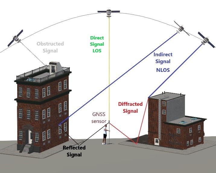
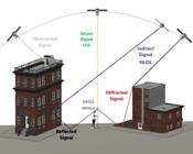
The term multipath generally refers to the situation when a GNSS antenna captures both direct (Line-Of-Sight - LOS) and indirect (Non-Line-Of-Sight - NLOS) signals simultaneously (Figure 1). In addition to the direct signals, there may also be reflected and/or diffracted signals that are easily tracked by the GNSS antenna. The pseudorange measurements are impacted by the extra path length caused by the reflected or diffracted signal. This issue can result in significant errors (about 100 m) in code and carrier phase measurements and is, therefore, treated as a harmful interference (Diggelen, 2009).
The magnitude of the error caused by multipath in any GNSS measurement depends mainly on four factors: 1) the reflecting surface, 2) the satellite/antenna geometry, 3) the type of antenna, and 4) the hardware and firmware of the receiver (Petropoulos and Prashant, 2021). Since the satellite is constantly moving, the multipath effect generally varies over time (Spilker Jr. et al., 1996). Consequently, there is currently no general and accurate mathematical model to correct these errors (Wu et al., 2018).
Usually, trees, buildings, walls, vehicles, water mass, and surfaces near a GNSS receiver can induce multipath. Thus, the magnitude of the multipath can vary, as each surface has its own physical properties. According to Polezel et al. (2004), materials with higher reflection coefficients, such as iron, cause larger multipath errors than materials like wood.
On mobile devices, the multipath effect is even more pronounced due to the poor quality of GNSS antennas in terms of suppressing multipath related errors (Gogoi et al., 2018; Håkansson, 2019; Zhang et al., 2019). According to Geng et al. (2019), raw GNSS observations collected by smartphones are seriously affected by the multipath effect, which significantly impacts the final positioning accuracy.
Håkansson (2019) conducted investigations using raw GNSS data collected from the Nexus 9 tablet under different multipath conditions. The author observed errors of tens of meters in code measurements without multipath mitigation.
Wen et al. (2020) performed PPP (Precise Point Positioning) with ambiguity resolution using observations from a GNSS antenna coupled with a Xiaomi Mi 8 smartphone. The results obtained by the authors indicated that it is possible to achieve centimeter level accuracy. Additionally, the study shows that ambiguity fixed solutions are possible under certain conditions. However, the authors point out that, due to the vulnerability of the smartphone GNSS antenna to multipath effects, accurate positioning is a significant challenge.
Many studies in GNSS literature address the so-called multipath effect (Petropoulos and Prashant, 2021; Polezel et al., 2004; Souza, 2008; Suzuki and Amano, 2021; Wu et al., 2018; Zhang et al., 2019; Zimmermann et al., 2019). Multipath mitigation techniques can be classified as location-dependent, hardware-based, or algorithm-based data processing techniques (Petropoulos and Prashant,2021). Nasr-Azadani et al. (2023), performed a comparative analysis of two algorithms, Code Minus Carrier Delta range (CMCD) and Signal Selection, to assess their performance in detecting multipath effects on smartphones. The findings show that signal selection, using signal-to-noise ratio (SNR)-dependent elevation angles, significantly aids in identifying multipath or NLOS observations.
On the other hand, there is specific equipment, such as Choke Ring 3D antennas, designed to minimize this error. However, these GNSS antennas usually cost thousands of dollars and are used for specific geodetic applications. Moreover, for moving or kinematic applications, the use of a Choke Ring antenna, which typically weighs up to 5 kg, can pose challenges in certain scenarios.
In the Brazilian context, the Laboratory of Space Geodesy and Hydrography (LAGEH - Laboratório de Geodésia Espacial e Hidrografia) at the Federal University of Paraná (UFPR - Universidade Federal do Paraná) has been developing technological innovations for satellite-based positioning. As an example, is the Attenuator Multipath Effect (AEM), a portable material that attenuates electromagnetic signals affected by multipath.
The development of AEM-LAGEH was based on Electromagnetic Radiation Absorbing Materials technology, which absorbs these waves and converts them into heat (Viski, 2012). AEM-LAGEH is a foam immersed in a liquid chemical compound. Since it is a foam, it can be molded into different shapes and consists of a lightweight material. Several studies have already proven its effectiveness in mitigating multipath effects related to the L1 and L2 carrier phase (Viski, 2012; Viski et al., 2015).
Currently, the third version of AEM-LAGEH (AEM-LAGEH 3) stands out for delivering similar results to a Choke Ring 3D model antenna (LEIAT504). In experiments conducted by Krueger et al. (2012), AEM-LAGEH 3 minimized multipath effect by 28%, while the Choke Ring 3D antenna reduced it by 34%, for the L1 carrier phase.
This study presents the results of the performance of AEM-LAGEH 3 in smartphone applications. Furthermore, as the AEM-LAGEH 3 was designed for conventional GNSS antennas, a new prototype called AEM-LAGEH Smart was developed, intended for smartphones GNSS positioning. The design of AEM-LAGEH SMART was tailored to fit smartphones. As this was a preliminary study, only a thin layer of the chemical compounds was applied, unlike AEM-LAGEH 3, which was fully immersed multiple times.
It is important to highlight that this study contributes valuable GNSS data collected with smartphones over an extended period, distinguishing itself from many related studies that only examine short periods of GNSS data collected using smartphones.
This article is based on a chapter previously published in the doctoral thesis titled “Avaliação e mitigação do efeito do multicaminho no posicionamento GNSS via smartphones” (Gomes, 2023). The decision to republish this content as an article aims to reach a wider audience and foster further discussions on the topic.
The paper is structured as follows: Section 2 presents some considerations regarding GNSS antennas. The methodology is described in Section 3, followed by the main results and discussions in Section 4. Finally, conclusions are drawn in Section 5.
2. GNSS receiver antenna
In addition to electromagnetic waves emitted by positioning satellites, antennas receive a variety of unwanted waves that are within the reception bandwidth, so it is essential that the antenna has a uniform gain. Gain is a measure of how receptive an antenna is to an electromagnetic wave as a function of: the signal’s incident direction (azimuth and elevation angle) on the antenna and its polarization (Kaplan and Hegarty, 2017; Morton et al., 2020).
The GNSS signals are right-hand circularly polarized (RHCP). Nonetheless, specular reflection from a surface at normal incidence results in a left-hand circularly polarized (LHCP) reflected signal. Therefore, GNSS antennas are often designed to have higher gain for RHCP signals (Morton et al., 2020).
In the research carried out by Ur et al. (2016), as expected, the position accuracy using the RHCP antenna was much better compared to the receiver equipped with the LHCP antenna. Furthermore, according to their research, the results show that the SNR recorded by RHCP antenna is roughly 6 dB higher than the SNR recorded with the LHCP antenna.
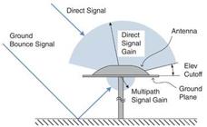
The installation structure around a GNSS antenna can significantly affect the satellite signals, consequently influencing the overall quality of GNSS positioning. Figure 2 contains an example of an idealized antenna, where the gain in the satellite direction is enhanced and the gain in the multipath direction is attenuated. In addition to the elevation mask (cutoff), the enhancement of the direct signal gain can be obtained from several factors related to the antenna design, such as the spiral elements and the dimension of the horizontal plane of the antenna.
One of the main problems of GNSS receivers is the high sensitivity, as it tracks not only the direct signals, but also the reflected and diffracted signals on surfaces. However, the existence of GNSS in smartphones depends precisely on this high sensitivity, as the GNSS antennas present in these devices are very small and the signal inside the smartphone is very weak (Morton et al., 2020). In addition, in certain situations, the sensitivity of the GNSS receiver is also necessary, especially where there are several obstructions, such as in big cities with large buildings.
Smartphones are usually equipped with a Planar Inverted-F Antenna (PIFA) (Banville et al., 2019). In general, to minimize the sensor dimension, the smartphone antenna is linearly polarized and has a pattern gain that allows it to track signals from all directions. Thus, smartphones are more susceptible to multipath interference and the reception of indirect signals, resulting in higher code noise and multipath (Banville et al., 2019; Morton et al., 2020). Additionally, an indirect signal can be stronger than a direct signal thanks to the attenuation suffered by direct signals along the axis of the dipole antenna (Morton et al., 2020).
3. Methodology
3.1 Multipath calculation
To characterize the multipath, a linear combination of pseudorange and carrier phase measurements was used (Seepersad and Bisnath, 2015). The pseudorange and noise multipath estimation on L 1 (MP1) is presented in Equation 1 and on L 5 (MP5) in Equation 2:
Where P 1 is the pseudorange measured on L1, P 5 is the pseudorange measured on L5, and
With frequencies f 1 =L 1 frequency 1575.42 MHz and f 5 =L 5 frequency 1176.45 MHz.
3.2 Test area and experimental setup
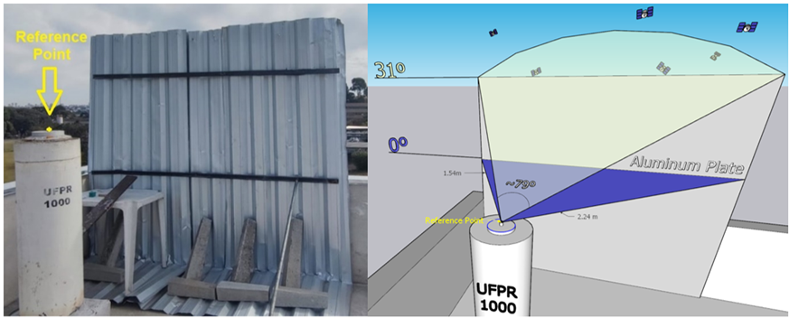
The study area was established on the UFPR 1000 pillar (Approximate geodetic coordinates: -25° 26´ 55.06˝ latitude, -49° 13´ 52.30˝ longitude), located on the terrace of the Camil Gemael Astronomy Laboratory (Figure 3). Therefore, in order to induce the multipath effect, an aluminium plate was positioned close to the base of the pillar column, as shown in Figure 4. The aluminium plate provides an obstruction of about 31° (elevation angle) and 79° (horizontal angle) with respect to the reference point.

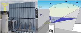
Aluminium plate next to UFPR 1000 pillar (left) and the obstruction angles provided by the aluminium plate (right).
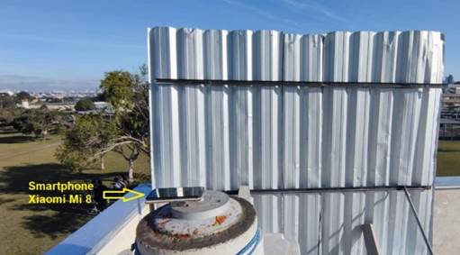
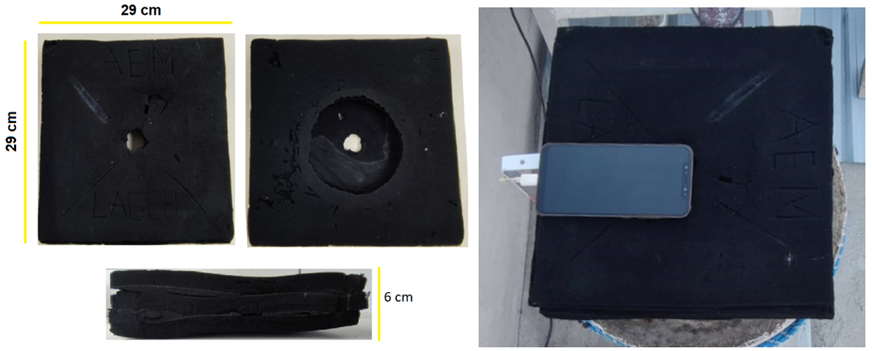
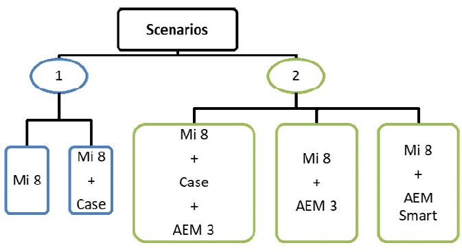
Two scenarios were idealized: 1) using only the smartphone (Figure 5) and 2) using the smartphone associated with some equipment. The equipment employed in the second scenario are basically the AEM LAGEH 3 (Figure 6), a waterproof plastic case for the smartphone (Figure 7), and the AEM LAGEH Smart (Figure 8).

Scenario 1: smartphone Xiaomi Mi 8 and the aluminium plate employed to generate multipath effect on GNSS signals.


Figure 9 shows the main characteristics of each scenario conducted with the presence of the aluminium plate next to the pillar.
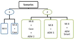
Characteristics of the scenarios. In scenario 1, only the smartphone and the waterproof case were used, while in scenario 2, the attenuators and case were used.
3.3 Data collection and post-processing
Data collection was carried out with a free app available on Google Play, called Geo++ Rinex Logger. The app allows access to raw GNSS data referring to multi-constellations (e.g., GPS, GLONASS, Galileo and BeiDou) and multi-frequencies (e.g., L1, L5, E1a, E5a, B1, B2). The recording rate used by the app is equal to 1 Hz and there is no elevation mask option. In addition, the app can automatically store the data in RINEX files with 1 hour duration. It is important to mention that there is also the “keep screen on while logging” function, which was used to prevent the smartphone screen from turning off and causing interruptions during data collection (Geo++, 2017).
The smartphone selected was the Xiaomi Mi 8 (Android version: 10) which can provide the GNSS raw data and contains a dual frequency GNSS sensor, the BCM47755 (Technology, 2018). The sensor is compatible with: GPS (L1 and L5), GLONASS (L1), Galileo (E1 and E5) and BeiDou (B1). During all campaigns, the available function on Android, called “Force Full GNSS measurements”, was also used to prevent interruptions during data collection. The data collection time was set from 17:00 (UTC-3) to avoid the time of day with the highest solar radiation intensity and to prevent possible overheating
In total, 15 campaign were conducted with at least 17 hours duration (17 RINEX files), the main characteristics are presented in Table 1. Furthermore, the Topcon Hiper SR geodetic receiver (GPS and GLONASS, L1 and L2) was used in one campaign (campaign15), for comparison purposes.
The post-processing data was conducted using the IBGE-PPP Brazilian online service (IBGE, n.d.). The main characteristic of this service are: use the Precise Point Positioning (PPP) technique; free of cost; utilize 10° cutoff; process information from GPS and GLONASS and recognized the L1 and L2 carrier phases (IBGE, 2017). Despite the smartphone used in these assessments tracking and storing information from the mentioned constellations and frequencies, the processing via IBGE-PPP only considered data from the GPS and GLONASS constellations and the L1 frequency.
In total, 276 RINEX files were sent for processing in IBGE-PPP, each lasting about 1 hour. The same archives were analyzed in TEQC software (UNAVCO, n.d.) to obtain the multipath values (MP1 and MP5).
For positional quality assessment, the ground truth coordinates of the Pillar UFPR 1000 (UTM North (N R ), UTM East (E R ) and the ellipsoidal height (h R )) (Huinca, 2009), were used to obtain the discrepancies or bias (∆), as shown in Equation 4 (Monico et al., 2009).
where: N, E and h are the coordinates obtained via IBGE-PPP (2000.4 epoch). The standard deviation of an isolated observation (σi) and the precision of the sample mean (σx) are obtained from Equation 5 and Equation 6, respectively:
The North (N), East (E) and ellipsoidal height (h) accuracies, were calculate using the bias (∆) and the standard deviation (σx) obtained from the GNSS processing coordinates using IBGE-PPP, as shown in Equation 7. The planimetric (2D) and planialtimetric (3D) accuracies (Acc) were calculated via Equations 8 and 9, respectively:
4. Results
4.1 Multipath
As mentioned previously, each RINEX observation file with 1 hour duration was analyzed in TEQC software. Table 2 shows the multipath root mean square (RMS) for L1 (MP1) and L5 (MP5), to each observation file generated during the Campaign 11 (characteristic: Mi 8 + AEM Smart).
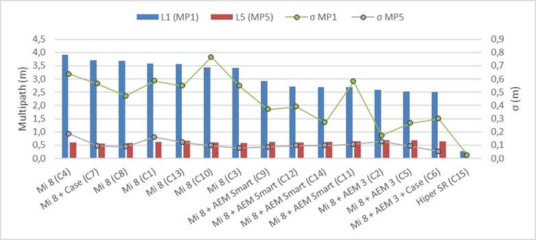
Table 3 contains L1 (MP1) and L5 (MP5) multipath results, as well as statistics such as multipath standard deviation (σ) and average () for each campaign. These results are also illustrated in Figure 10.
L1 (MP1) and L5 (MP5) multipath average values and the standard deviation in each campaign.

The most evident results shown in Table 3 and illustrated in Figure 10 are the differences between MP1 and MP5 multipath indices. Carrier phase L5 presented superior performances for all campaign scenarios, providing the lowest MP values. Furthermore, evaluating the MP consistency using the standard deviations, the highest standard deviation in MP5 was 0.19 m, while the lowest standard deviation value was 0.05 m, which is close to the MP1 value obtained in the HiPer SR geodesic receiver campaign (0.02 m). This reaffirms the consistency and quality of the L5 signal.
Since it is crucial to consider the different equipment set, when assessing multipath effects mitigation performances, Table 4 brings the average and standard deviation of the values related to L1 (MP1) and at L5 (MP5) multipath for the different equipment setups/combinations involved in the experiments. For visual analysis purposes, these results are also shown in Figure 11.
Statistics for MP1 and MP5 considering the different equipment setups/combinations adopted in this study.
According to Table 4, the best results were obtained with the combination Mi 8 + AEM 3. Also, this fusion results in the lowest MP1 value, around 2.54 m, and provide the best consistency, as its standard deviation was lower than the others, around 0.25 m.
Considering the average multipath values in Table 4, a significant improvement is observed when using L5 (MP5) compared to L1 (MP1). The combinations Mi 8, Mi 8 + AEM Smart, and Mi 8 + AEM 3 show improvements of approximately 83%, 78%, and 74%, respectively. This indicates that the use of L5 can result in better multipath data.
Finally, it is also important to highlight that the highest values in MP1 were achieved in campaigns performed only with the Mi 8.
Another consideration made concerns the variability of the data through the analysis of the coefficient of variation (CV). The most consistent MP1 values are from the Mi 8 + AEM 3 combination, with a CV of about 10%, while the Mi 8 + AEM Smart and Mi 8 alone resulted in about 15% and 16%, respectively. In the context of MP5, again, the Mi 8 + AEM 3 combination shows the least variability in the data (14%), followed by the Mi 8 + AEM Smart combination (16%), while the Mi 8 alone resulted in a higher coefficient of variation, around 20%. Although the average is quite different between MP1 and MP5, the CVs are close, indicating that the consistency of the methods is practically equivalent.
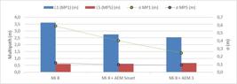
Average and multipath standard deviation (σ) in L1 (MP1) and L5 (MP5) referring to each characteristic.
From the results presented in Figure 11, it is interesting to remark a considerable reduction of MP1 values obtained for the GNSS smartphone observations. These improvements stand by approximately 24% and 30% using the AEM Smart and AEM 3, respectively, in comparison to those results where the AEM was not employed.
4.1 Accuracy
Table 5 shows the results from GNSS data processing of the Campaign 11. It can be observed that, as expected the average () of the formal standard deviations (σ) from GNSS data processing is lower than the standard deviations (σx) of the differences between the estimated coordinates with respect to those adopted as reference coordinates. Thus, in order to avoid overestimating the results quality, it was decided to use the highest values of standard deviations (σx) from the external comparison to compute the accuracies for all the campaigns.
Campaign 11 - Formal Standard Deviation (σ) obtained from GNSS data processing (PPP Solutions) and differences (Δ) with respect to the reference coordinates.
Table 6 contains the mean standard deviation from the set of all PPP solutions, and average of the differences between the results from GNSS data processing coordinates for each equipment combination (campaign) and the reference geodetic coordinates. It is worth noting that the IBGE-PPP is not compatible with L5, therefore, all campaigns conducted with the Mi 8 were processed considering only L1 (single frequency). Thus, the data collected by the geodetic receiver were processed considering the combination of L1+L2 (dual frequency) and L1 only.
Statistics (mean standard deviation (σx)) obtained from GNSS data processing (PPP) results and differences (Δ) between the ground truth coordinates for each equipment combination (campaign - C).
The accuracy achieved for each coordinate component (North, East, and ellipsoidal height), as well as the planimetric (2D) and planialtimetric (3D) accuracies for each equipment combination (campaign) are presented in Table 7. Figure 12 contains the same values presented in this table and the average values referring to the multipath effect on the L1 carrier phase (presented in Table 3). It is important to mention that Figure 12 does not bring the results for the geodetic receiver, since its positioning accuracy results are too small compared to those results obtained with the smartphone GNSS observations.
The best results were achieved by the campaign carried out with the HiPer SR geodesic receiver. Considering the L1+L2 combination, an accuracy of approximately 0.03 meters and 0.04 meters was obtained for 2D and 3D, respectively, while processing using only L1 resulted in 2D and 3D accuracy of approximately 0.13 meters and 0.19 meters, respectively.

2D and 3D accuracies and the corresponding L1 multipath average results for each campaign performed with the smartphone.
All campaigns performed with the smartphone associated with the proposed AEMs resulted in accuracies below 0.50 meters and better than 1.4 meters for 2D and 3D accuracy, respectively. Notably, the average MP1 values in these campaigns were lower than 2.67 meters. In contrast, campaigns conducted with the Mi 8 yielded higher values, with results exceeding 1.2 meters and 2.4 meters for 2D and 3D accuracies, respectively, and MP1 values greater than 3.4 meters. Consistent with the planimetric accuracies (2D), the best planialtimetric accuracies (3D) were also achieved in campaigns where the equipment combination included attenuators. Specifically, the best 3D accuracy result was obtained in Campaign 5, where the smartphone was used alongside the AEM LAGEH 3.
When comparing the results from campaigns C6 and C7, which involved the use of the case, it is evident that the case does not significantly impact the outcomes. Therefore, it can be used in scenarios where precipitation may occur without a considerable effect on the results.
Regarding the differences between the AEM’s, it is clear that AEM 3 provided better 2D accuracy compared to all campaigns using AEM Smart. This difference may be attributed to the distinct design of the two AEMs and the varying amounts of chemical compounds applied to each.
Additionally, the spatial distribution of the data presented in Figure 12 reveals a tendency in the accuracies and the multipath in L1. To further investigate this, an analysis using Pearson’s correlation was conducted. The correlation coefficient, which measures the extent to which two variables co-vary, was used. Analysis of the campaigns using only the smartphone showed a high correlation, approximately 94.6% and 93.3%, between L1 (MP1) multipath and 2D and 3D accuracies, respectively.
5. Conclusions
In this contribution, 260 hours of GNSS data collected via the Xiaomi Mi 8 smartphone were assessed through GNSS positioning and multipath index analysis. The results provide important insights into GNSS positioning via smartphone and its relationship with multipath.
In the campaigns conducted with the smartphone only, MP1 values greater than 2.5 meters were obtained, while the highest MP5 value found was equal to 0.68 meters (Campaign 2). Also, the standard deviations related to multipath in L1 and L5 showed consistency, following a trend of approximately 0.10 meters, even in campaigns with attenuators. Furthermore, when evaluating the average multipath values for each signal, L5 demonstrated better results, with improvements of more than 73% compared to L1 when using the AEMs, and more than 83% when using the smartphone only. Although the attenuators provided better results in MP1, it cannot be concluded that they significantly affected MP5 values.
In relation to the comparison between L5 and L1, this improvement can be attributed to the higher chipping rate of the L5 signals compared to those of the L1 band. This elevated chipping rate enhances the signal’s resilience against multipath effects, making L5 significantly less susceptible to interference from reflected signals.
Regarding the efficiency of the AEMs, it can be stated that the AEM 3 provided better results. However, this may be related to the characteristics of the object, such as its dimensions (e.g., thickness, width and length), the amount, and the region where the chemical product was applied. The AEM Smart has only a small layer of chemical (on the underside), while the AEM 3 was completely coated several times. Therefore, new experiments should be carried out to identify the best AEM design (number of layers, thickness, etc.), as well as the region and amount of chemical material, to achieve better results.
Another important issue concerns the reduction of MP1 values obtained with the combinations. A reduction of approximately 24% and 30% was observed when using AEM Smart and AEM 3, respectively. Furthermore, a high correlation, around 94%, was detected between MP1 values and 2D and 3D accuracies. Therefore, it is concluded that multipath directly affects the accuracy obtained via the Xiaomi Mi 8 smartphone.
All campaigns carried out using only the smartphone resulted in planimetric accuracy (2D) between 1.22 m and 2.46 m. The Mi 8 + AEM Smart combination provided 2D positional accuracy between 0.33 m and 0.47 m, while the Mi 8 + AEM 3 combination provided 2D accuracy between 0.24 m and 0.32 m.
The best result regarding 3D accuracy with the smartphone was achieved with the Mi 8 + AEM 3 combination (C5), which yielded a value of approximately 0.60 m. All campaigns conducted with the AEMs resulted in planialtimetric accuracy (3D) between 0.60 m and 1.32 m. In contrast, the 3D results using only the smartphone ranged between 2.48 m and 4.15 m.
As expected, the best results for both MP1 values and positional accuracy were obtained with the Topcon HiPer SR geodesic receiver. However, it is worth mentioning that the IBGE-PPP service utilized both carrier phases (L1 and L2), unlike the data collected via smartphone, which were processed using only the L1 carrier phase. Therefore, it is interesting to note that the L1+L2 combination (dual frequency) resulted in an improvement of approximately 76% and 79% in 2D and 3D accuracy, respectively, compared to the solution using only L1 (single frequency). This is an important consideration regarding the accuracy.
In this context, another significant issue concerns the elevation mask adopted by the IBGE-PPP (10°). If processing is conducted with an elevation mask (cutoff) equal to 0°, the attenuators may provide more significant results.
All campaigns were carried out with the smartphone positioned horizontally. However, further investigations will be conducted to identify the optimal attitude for data collection. Subsequently, the design of the attenuators may be adapted to achieve the best possible performance.
We also recommend conducting investigations using different tracking rate intervals (e.g., 10 s and 30 s) and durations (e.g., 10 min, 30 min, and periods longer than 1 hour) to enhance the investigation by considering other characteristics.
Finally, from the results of this research, it can be concluded that the attenuators contributed to the mitigation of the multipath effect experienced in the L1 carrier phase. Consequently, the positional accuracy obtained via IBGE-PPP was also improved. Considering the average of the 2D and 3D accuracies obtained with Mi 8 alone and Mi 8 + Case configuration (campaigns 1, 3, 4, 8, 10, 13, and 7), and comparing with the average obtained from the other campaigns, we observe an improvement of over 80% and 66% in the 2D and 3D accuracies, respectively.
In addition, in a future update of the IBGE-PPP service that recognizes the L5 carrier phase, more promising results can be achieved from positioning via smartphones with dual frequency GNSS sensors. With this new information, researchers can better understand the relationship between multipath and GNSS positioning accuracy and work towards improving positioning technology for various applications.
ACKNOWLEDGEMENT
This work was carried out as part of the main author’s doctoral thesis, financed by Coordenação de Aperfeiçoamento de Pessoal de Nível Superior - CAPES (Process number: 40001016002P6).
REFERENCES
-
BANVILLE, S.; LACHAPELLE, G.; GHODDOUSI-FARD, R.; GRATTON, P. Automated Processing of Low-Cost GNSS Receiver Data , p. 3636-3652, 2019. Available in: <Available in: http://www.ion.org/publications/abstract.cfm?jp=p&articleID=16972 >. [Accessed 11 out. 2021].
» http://www.ion.org/publications/abstract.cfm?jp=p&articleID=16972 - DIGGELEN, F. VAN. A-GPS : assisted GPS, GNSS, and SBAS London: Artech House, 2009.
- GENG, J.; JIANG, E.; LI, G.; XIN, S.; WEI, N. An improved Hatch filter algorithm towards sub-meter positioning using only android raw GNSS measurements without external augmentation corrections. Remote Sens Basel, v. 11, n. 14, p. 20, 2019. MDPI AG.
-
GEO++. Logging of GNSS Raw Data On Android Geo++ Available in: <Available in: http://www.geopp.de/logging-of-gnss-raw-data-on-android/ >. [Accessed 1 out. 2018].
» http://www.geopp.de/logging-of-gnss-raw-data-on-android/ - GOGOI, N.; MINETTO, A.; LINTY, N.; DOVIS, F. A Controlled-Environment Quality Assessment of Android GNSS Raw Measurements. Electronics, v. 8, n. 1, p. 5, 2018. MDPI AG.
-
GOMES, A., 2023. Avaliação E Mitigação Do Efeito Do Multicaminho No Posicionamento GNSS Via Smartphones Universidade Federal do Paraná. Available in: <Available in: https://acervodigital.ufpr.br/handle/1884/83478 >. [Accessed 16 feb. 2024].
» https://acervodigital.ufpr.br/handle/1884/83478 -
HÅKANSSON, M. Characterization of GNSS observations from a Nexus 9 Android tablet. GPS Solutions, v. 23, p. 21, 2019. Available in: <Available in: https://doi.org/10.1007/s10291-018-0818-7 >. [Accessed 3 may. 2019].
» https://doi.org/10.1007/s10291-018-0818-7 - HUINCA, S. C. M. Calibração Relativa de Antenas GNSS na BCAL/UFPR, 2009. Curitiba: Universidade Federal do Paraná.
- IBGE. Manual do Usuário Aplicativo Online IBGE-PPP Rio de Janeiro, 2017.
-
IBGE, n.d. IBGE-PPP - Serviço online para pós-processamento de dados GNSS. Available in: <Available in: https://www.ibge.gov.br/geociencias/informacoes-sobre-posicionamento-geodesico/servicos-para-posicionamento-geodesico/16334-servico-online-para-pos-processamento-de-dados-gnss-ibge-ppp.html?=&t=processar-os-dados >. [Accessed 31 jul. 2024].
» https://www.ibge.gov.br/geociencias/informacoes-sobre-posicionamento-geodesico/servicos-para-posicionamento-geodesico/16334-servico-online-para-pos-processamento-de-dados-gnss-ibge-ppp.html?=&t=processar-os-dados - KAPLAN, E. D.; HEGARTY, C. J. Understanding GPS/GNSS Principles and Applications 2017.
- KRUEGER, C. P.; HUINCA, S. C. M.; LEANDRO, D.; VISK, A. R. A INOVAÇÃO DE PRODUTOS QUE CONTRIBUIRÃO PARA O POSICIONAMENTO POR SATÉLITES COM ALTA PRECISÃO. III Simpósio Brasileiro de Geomática. Anais... . p.218-222, 2012. Presidente Prudente.
- MONICO, J. F. G.; DAL PÓZ, A. P.; GALO, M.; DOS SANTOS, M. C.; DE OLIVEIRA, L. C. Acurácia e precisão: Revendo os conceitos de forma acurada. Boletim de Ciencias Geodesicas, v. 15, n. 3, p. 469-483, 2009.
- MORTON, Y. T. J.; DIGGELEN, F. VAN; SPILKER, J. J. J.; PARKINSON, B. W. Position, Navigation, and Timing Technologies in the 21st Century Integrated ed. John Wiley & Sons, Inc., Hoboken, New Jersey, p. 551 - 589, 2020.
- NASR-AZADANI, S.; ALIZADEH, M. M.; SCHUH, H. Detecting Multipath Effects on Smartphone Gnss Measurements Using Cmcd and Elevation-Dependent Snr Selection Technique. ISPRS Annals of the Photogrammetry, Remote Sensing and Spatial Information Sciences, v. 10, n. 4/W1-2022, p. 595-602, 2023.
- PETROPOULOS, G. P. .; PRASHANT, K. S. (ORGS.). GPS and GNSS Technology in Geosciences Elsevier, 2021.
- POLEZEL, W. G. C.; SOUZA, E. M. DE; MONICO, J. F. G. Análise dos fatores que influenciam o Multicaminho. Congresso Brasileiro de Cadastro Técnico Multifinalitário - COBRAC. Anais... . p.10, 2004. Florianópolis, SC.
-
SEEPERSAD, G.; BISNATH, S. Reduction of PPP convergence period through pseudorange multipath and noise mitigation. GPS Solutions , v. 19, n. 3, p. 369-379, 2015. Springer Berlin Heidelberg. Available in: <http://dx.doi.org/10.1007/s10291-014-0395-3>. [Accessed 16 nov. 2021].
» https://doi.org/http://dx.doi.org/10.1007/s10291-014-0395-3 - SOUZA, E. M. DE. Análise de wavelets para detecção e correção do multicaminho no posicionamento relativo GNSS estático e cinemático, 2008. Universidade Estadual Paulista - Presidente Prudente.
- SPILKER JR., J. J.; AXELRAD;, P.; PARKINSON;, B. W.; ENGE, P. Global Positioning System: Theory and Applications, Volume I. 1996.
-
SUZUKI, T.; AMANO, Y. NLOS Multipath Classification of GNSS Signal Correlation Output Using Machine Learning. Sensors 2021, Vol. 21, Page 2503, v. 21, n. 7, p. 2503, 2021. Multidisciplinary Digital Publishing Institute. Available in: <Available in: https://www.mdpi.com/1424-8220/21/7/2503/htm >. [Accessed 16 nov. 2021].
» https://www.mdpi.com/1424-8220/21/7/2503/htm - TECHNOLOGY, B. S. Dual Frequency performance in mass market 2018.
-
UNAVCO, n.d. TEQC software. Available in: <Available in: https://www.unavco.org/software/data-processing/teqc/teqc.html > [Accessed 31 jul. 2024].
» https://www.unavco.org/software/data-processing/teqc/teqc.html - UR, R.; LIGHARI, R.; BERG, M.; et al. Analysis of the measured RHCP and LHCP GNSS signals in multipath environment; Analysis of the measured RHCP and LHCP GNSS signals in multipath environment. 2016 International Conference on Localization and GNSS (ICL-GNSS), 2016.
-
VISKI, A. R. ANÁLISE DA ATENUAÇÃO DO EFEITO MULTICAMINHO NO POSICIONAMENTO GPS DE PLATAFORMAS LAGRANGEANAS E EULERIANAS EM MASSAS DE ÁGUA, 2012. Universidade Federal do Paraná. Available in: <Available in: https://acervodigital.ufpr.br/bitstream/handle/1884/41291/R - D - ANDERSON RENATO VISKI.pdf?sequence=2 >. [Accessed 16 nov. 2021].
» https://acervodigital.ufpr.br/bitstream/handle/1884/41291/R - D - ANDERSON RENATO VISKI.pdf?sequence=2 - VISKI, A. R.; KRUEGER, C. P.; BLENINGER, T. USO DE ISOLANTE ELETROMAGNETICO NA ATENUAÇÃO DO EFEITO MULTICAMINHO NO POSICIONAMENTO GPS DE PLATAFORMAS EULERIANAS EM MASSAS DE ÁGUA Use of Insulation in Electromagnetic Mitigation in Effect Multipath GPS Positioning Platform Eulerian Masses in Water. Revista Brasileira de Cartografia, p. 12, 2015.
- WEN, Q.; GENG, J.; LI, G.; GUO, J. Precise point positioning with ambiguity resolution using an external survey-grade antenna enhanced dual-frequency android GNSS data. Measurement, v. 157, p. 107634, 2020. Elsevier.
- WU, R.; WANG, W.; LU, D.; WANG, L.; JIA, Q. Multipath Interference Suppression. In: Adaptive Interference Mitigation in GNSS. Navigation: Science and Technology. Singapore: Springer, 2018.
-
ZHANG, Z.; LI, B.; GAO, Y.; SHEN, Y. Real-time carrier phase multipath detection based on dual-frequency C/N0 data. , v. 23, p. 7, 2019. Available in: <Available in: https://doi.org/10.1007/s10291-018-0799-6 >. [Accessed 20 out. 2021].
» https://doi.org/10.1007/s10291-018-0799-6 -
ZHAO, X.; ZHAN, X.; YAN, K. GNSS vulnerabilities: simulation, verification, and mitigation platform design. Geo-spatial Information Science, 2013. Available in: <Available in: https://www.tandfonline.com/action/journalInformation?journalCode=tgsi20 >. [Accessed 6 jul. 2020].
» https://www.tandfonline.com/action/journalInformation?journalCode=tgsi20 - ZIMMERMANN, F.; SCHMITZ, B.; KLINGBEIL, L.; KUHLMANN, H. GPS multipath analysis using fresnel zones. Sensors (Switzerland), v. 19, n. 1, p. 1-25, 2019.