 Compact Star Shaped Swastika Stub Integrated Multiband Printed Antenna for Ku/K/Ka Band Application
Abstract
The triple-band operation of a microstrip patch antenna on an FR4 substrate is demonstrated, covering Ku-, K-, and Ka-bands. The antenna features a star-shaped patch with a swastika stub on the FR4 dielectric substrate, activated by a 50-ohm microstrip transmission line. The Finite Integration Technique (FIT) is employed in computer simulations, aligning with a comprehensive investigation. The lower band exhibits measured impedance bandwidths with a VSWR of 2:1 at 3.02 GHz (11.83 to 14.93 GHz), 4.29 GHz (16.42 to 20.72 GHz), 1.85 GHz (21.38 to 23.40 GHz), and 3.49 GHz (23.74 to 27.09 GHz). This innovative antenna design showcases versatility across frequency bands, with the FR4 substrate contributing to its production. The activated microstrip transmission line ensures efficient signal transmission with stable 50-ohm impedance. The FIT-based simulation tool enhances precision in predicting the antenna's behavior. Within the operational frequency range, the antenna demonstrates a stable omnidirectional radiation pattern, crucial for its applications in communication systems. Comparisons between measurement and simulation findings validate the proposed prototype's performance, emphasizing the reliability of the FIT-based simulation tool. This comprehensive study highlights not only the antenna's operational capabilities but also the accuracy of the computational approach employed.
Keywords:
Microstrip Patch Antenna; Triple-Band Operation; FR4 Substrate; Finite Integration Technique (FIT); Omnidirectional Radiation Pattern
HIGHLIGHTS
The proposed microstrip patch antenna on an FR4 substrate demonstrates impressive triple-band operation covering Ku-, K-, and Ka-bands.
The star-shaped patch with a swastika stub design on the FR4 substrate showcases innovation in antenna geometry.
Utilizing the Finite Integration Technique (FIT) in computer simulations measured the antenna's measured performance.
INTRODUCTION
Developing a compact, cost-effective, highly portable, wide-ranging, and versatile planar antenna has emerged as a critical priority. This is driven by the escalating demands placed on wireless communication systems and the increasing requirements of diverse applications. In recent decades, there has been a substantial investment of research efforts in the field. Academics have concentrated on the propagation of antennas to meet diverse design objectives. Among the various options, printed planar microstrip patch antennas have emerged as a focal point of interest. This is attributed to their attractiveness in areas such as compact size, low weight, straightforward production processes, and their seamless compatibility with other elements within wireless apparatus.
Recent literature underscores the existence of numerous low-profile planar patch antennas, along with their capacity to operate across multiple frequency bands. Various innovative antenna designs have been explored to enhance performance and capabilities. These encompass a range of configurations, including the hexagonal-shaped triangular slotted antenna [1], stacked circular patch antennas [2], S-shaped microstrip patch antennas [3], square slotted patch antennas [4], and modified fork-shaped antennas with integrated parasitic elements [5]. Additionally, researchers have delved into techniques involving the incorporation of shorting pins or walls [6], as well as the integration of strips [7] to augment functionality. Moreover, significant progress has been achieved through the introduction of stubs or supplementary components to either the ground plane or the radiating patch [7, 8]. These endeavors represent a concerted effort to diversify and refine antenna design methodologies, resulting in a broader spectrum of options for various applications in wireless communication and technology. Top of Form
Microstrip patch antennas exhibit limitations such as restricted bandwidth, modest gain, and an amplified influence of cross-polarization, all of which are regarded as their drawbacks. Expanding the bandwidth without altering the antenna's dimensions, cost, or weight is a challenging endeavor due to the heightened bandwidth requirements of contemporary communication systems and devices catering to diverse applications. This complicates the achievement of this objective. Enhancing the patch antenna's bandwidth can be approached through several strategies. These encompass employing a thicker substrate, utilizing a material with lower dielectric constant, or integrating slots and stub elements into the radiating patch structure.
Furthermore, adjustments to the size and shape of the slots can contribute to bandwidth augmentation. These alterations may involve variations like rectangular slots [9], circular slots [10], octagonal slots [11], fractal-shaped slots [12], or modified and partial slots [13]. Incorporating a ground plane [13, 14] can also prove advantageous in attaining the desired bandwidth around the anticipated resonant frequency.
In contemporary communication systems, the utilization of large dish antennas in radar and satellite applications has progressively given way to smaller, more streamlined antenna alternatives. Traditional satellite antennas functioning at ultra-high frequency or very high frequency necessitate increasing antenna dimensions as wavelengths become longer [15]. In contrast, satellite antennas functioning within the Ku/K band exhibit compactness, reduced initial investment requirements, enhanced cost-effectiveness, and heightened reliability. The utility of these antennas spans from individual satellites to satellite constellations, as well as various wireless communication scenarios and educational contexts [16]. A thorough investigation has been carried out in the domain of planar dual-band antenna design, focusing particularly on the Ku/K frequency bands. The objective is to identify a low-profile antenna solution viable for satellite communication purposes.
Significant research efforts have been dedicated to the exploration of planar dual-band antenna designs tailored to the Ku/K frequency bands. The goal is to identify a compact antenna solution that can effectively serve satellite communication purposes. In recent times, a multitude of compact antenna concepts have emerged for applications within the Ku and K frequency bands. Here are some representative examples: the dual-layer multi-feed electromagnetic (EM) bandgap antenna [17], the triangular slotted microstrip patch antenna [18], an S-shaped patch antenna optimized for wideband applications [3], the double-S-shaped slotted patch antenna [19], a linear polarized planar filtenna [20], and a single-fed dielectric resonator antenna [21].
This manuscript introduces a design concept for a printed microstrip patch antenna that exhibits a compact, planar configuration and is capable of operating across the Ku, K, and Ka frequency bands. The proposed design employs a straightforward geometrical arrangement, achieved by combining two mutually perpendicular rectangular shapes with a swastika-shaped stub. Achieving the desired frequency bands is accomplished by fine-tuning parameters on the radiating patch. This process involves conducting numerical simulations utilizing the readily available CST software. The substrate employed is constructed from FR4 material, possessing a dielectric constant of 4.4. Subsequently, an antenna prototype is constructed based on the dimensions that have been optimized through simulation. This meticulous procedure ensures that the antenna performs optimally within the specified frequency ranges. The use of advanced simulation tools and precise material selection, such as the FR4 substrate, enhances the accuracy and effectiveness of the final antenna design. This systematic approach, from simulation to fabrication, underscores the importance of precision and empirical validation in the development of high-performance antennas.
The prototype antenna's performance is corroborated through experimental measurements, affirming its effectiveness in operating across four discrete frequency bands. Specifically, it operates within the ranges of 11.83 to 14.93 GHz for the Ku band, 16.42 to 20.72 GHz for the K band, and 21.38 to 23.40 GHz and 23.74 to 27.09 GHz for the Ka band, addressing applications in satellite communication and radar systems. The forthcoming sections delve into a comprehensive analysis and discussion of the geometrical design, aligning with parametric investigations, simulation outcomes, and the experimental findings.
ANTENNA DESIGN AND ITS PARAMETRIC
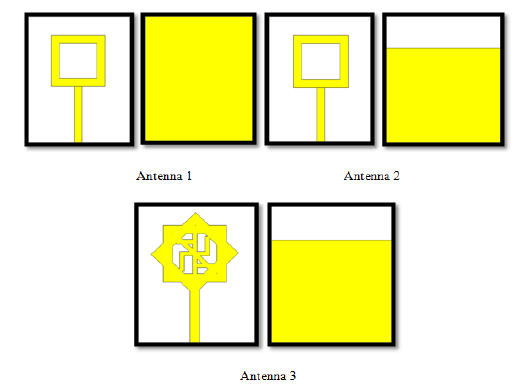
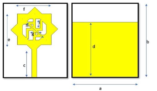
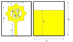
Figure 1 illustrates the evolutionary stages of the geometrical configuration for the Integrated Printed Antenna with Star Shaped Swastika Stub. The antenna was fabricated on an FR4 substrate, known for its relative permittivity of 4.4. This substrate choice is pivotal as it significantly influences the antenna's performance. By leveraging the unique properties of FR4, the antenna design can effectively achieve the desired electromagnetic characteristics. This includes factors like impedance matching, radiation pattern, and bandwidth. The integration of the Star Shaped Swastika Stub into the design further enhances its capabilities, allowing for optimized performance across specified frequency bands. This combination of precise geometry and tailored substrate material underscores the meticulous engineering involved in developing high-performance printed antennas. It represents a strategic fusion of design innovation and material science to create a functional and reliable antenna for diverse applications in modern wireless communication systems. The complete dimensions of the antenna measure 26 mm in width, 32 mm in length, and 1.6 mm in height. The region responsible for radiation occupies an area of 18.7 mm × 17.5 mm, encompassing the loading of the Swastika stub. The substrate maintains a thickness denoted as "j," while the design incorporates copper with a thickness denoted as "k". The antenna possesses a straightforward geometric configuration achieved through the integration of two rectangles which are orthogonal to each other, resulting in the creation of star shaped patch. This design facilitates the attainment of specified resonance frequencies while maintaining an acceptable bandwidth. The radiating patch is supplied with power through a Sub Miniature version A (SMA) connector using a 50Ω coaxial cable. The center conductor of the SMA establishes electrical continuity with the antenna's radiating element via a 12.4 mm long and 2.0 mm wide microstrip line. Conversely, the outer conductor links to the partial ground plane. The placement of the microstrip feed line at the midpoint of the antenna, precisely along the x-axis, ensures uniform distribution of electromagnetic energy to the radiator, optimizing its performance.
The antenna is designed using the below equation.
The equations incorporate the following variables:
"c" signifies the speed of light.
"fr" represents the resonant frequency.
"h" denotes the substrate's height.
"εeff" stands for the effective dielectric constant.
To evaluate the antenna's performance, a range of parameter configurations were adjusted to achieve the requisite resonance frequencies and bandwidths. To attain this objective, a numerical investigation was carried out employing CST, a software founded on the Finite Integration Technique (FIT) and comprehensive full-wave electromagnetic field simulation. This involved an extensive process of exploring various parameters and conducting multiple simulations. As a result, the most effective dimensions for these parameters have been successfully determined and are detailed in Table I. This rigorous analytical approach ensured precision in refining the antenna design for optimal performance. CST's application of FIT, coupled with its sophisticated electromagnetic field simulations, facilitated a thorough assessment of the antenna's behavior. The process involved systematically adjusting key variables and analyzing their effects on the antenna's characteristics. This iterative procedure led to the identification of dimensions that enhance performance across specified frequency bands. The culmination of this effort is presented in the detailed findings outlined in Table I, which serve as a valuable reference for constructing the optimized antenna prototype
The development process of the Star Shaped Swastika Stub Integrated Printed Antenna began by considering the established formulae commonly utilized for standard rectangular metallic antenna radiating patches [22-24]. The parametric analyses do not encompass substrate materials, the antenna's overall dimensions, or the feed location as independent variables, given their demonstrated significant impact on antenna performance. To holistically investigate the influence of specific elements on the reflection coefficient, a singular item was selected as the variable, while the other components were maintained constant throughout the entirety of the process.

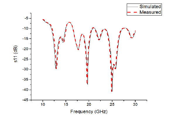
Figure 1 depicts the evolving geometric structure of the antenna in question. In contrast, Figure 2 showcases the suggested antenna along with its associated parameters. Figure 3 displays the corresponding performance of the antenna with regard to the reflection coefficient (S11). The achieved bandwidths of the suggested antenna are 3.02 GHz (11.83 to 14.93 GHz), 4.29 GHz (16.42 to 20.72 GHz), 1.85 GHz(21.38 to 23.40 GHz), and 3.49 GHz (23.74 to 27.09 GHz). The initial resonant mode is activated at distinct frequencies of 12.78, 17.64, 19.71, 22.28, and 25.01 GHz. Significantly, the wideband feature of the central operating band is enhanced by the inclusion of two extra resonant frequencies at 17.64 and 19.71 GHz. This notably contributes to the overall expansion of the band.
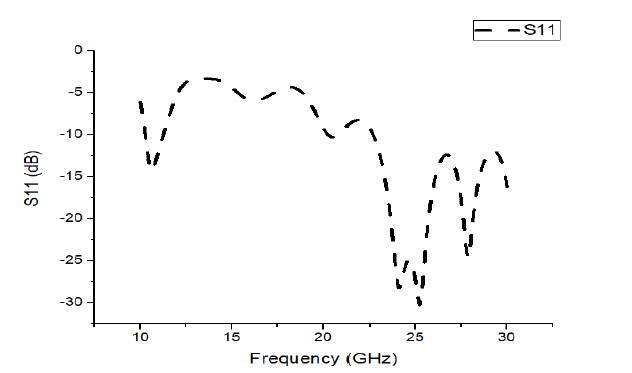
Illustrated in Figure 1, the evolution process is delineated into three stages. The first stage, Antenna 1, features a simple rectangular ring configuration with full ground coverage. This configuration resonates at 25 GHz and exhibits a wide bandwidth within the operational frequency range due to the inherent attributes of the rectangular ring structure. Figure 3 showcases the return loss characteristics of Antenna 1.
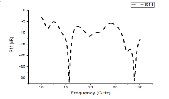
In the second stage, Antenna 2 is fashioned by reducing the ground size, inducing alterations in the inductance and capacitance of the antenna design. As a result, this results in dual-band operation at 15.8 GHz and 29.2 GHz. Figure 4 displays the return loss characteristics of Antenna 2.
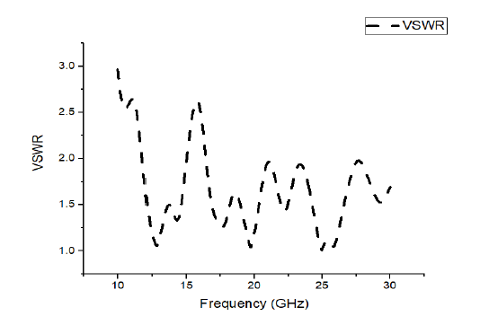
Moving to the third stage, Antenna 3 operates across frequencies of 12.78, 17.64, 19.71, 22.28, and 25.01 GHz. This is accomplished by introducing a vertical step along with the swastika stub. Figure 5 illustrates the return loss characteristics of Antenna 3. This adjustment leads to a significant increase in bandwidth across the Ku, K, and Ka bands. The Voltage Standing Wave Ratio (VSWR) features of the proposed antenna are depicted in Figure 6.

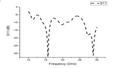
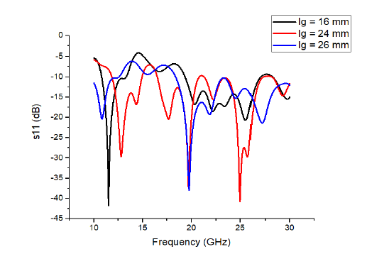
A comprehensive evaluation of key parameters including ground length (lg), feed width (wf), and patch width is conducted through parametric analysis to identify the optimal values that significantly influence the desired output. This process aims to select the parameter values that yield the desired antenna performance. The parametric analysis of the ground length is presented in Figure 5 and Figure 6, illustrating the range of ground lengths examined. Notably, it becomes evident from the figure that a ground length of 24 mm aligns with the desired outcomes, thus emerging as the most suitable choice for this parameter.
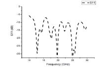

The ground length is investigated across a range spanning from 16 mm to 26 mm. After careful consideration, 24 mm is determined as the preferred ground length. This choice is underscored by its favorable impedance matching characteristics across all resonating bands, which leads to its selection as the final and optimal ground length
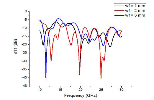
Upon close inspection of Figure 7 and Figure 8, a discernible pattern emerges. A systematic increase in feed width, spanning from 1 mm to 3 mm, reveals a noteworthy trend: the optimal feed width of 2 mm ensures comprehensive impedance matching across all operational bands. As a consequence, the designated ideal value for the feed width, denoted as "wf," is firmly set at 2 millimeters (mm). This meticulous analysis underscores the critical role of feed width in achieving optimal impedance characteristics for the antenna's performance. The observed trend reaffirms that the 2 mm value represents a finely-tuned balance, allowing the antenna to effectively resonate across a diverse range of operational frequencies. This careful consideration of feed width is pivotal in the design process, as it directly influences the antenna's ability to efficiently transmit and receive signals within the desired frequency bands. Thus, "wf=2 mm" serves as a crucial parameter, ensuring the antenna's peak performance across its specified range of operation.

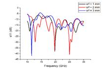
Figure 9 portrays the parametric assessment of the patch width "wp." The depicted configuration displays favorable impedance matching characteristics across all resonating bands when the patch width is set at 13.5 mm. Therefore, this value is deemed the most appropriate for practical implementation.

RESULTS AND DISCUSSION
Figure 10 provides a visual representation of the simulated surface current distributions at both the lower and upper resonant frequencies. The graphic vividly portrays that the current distribution across the radiating patch's surface exhibits non-uniformity across different resonating frequencies. In detail, during the lower resonant mode, the surface currents conspicuously concentrate around the feed line and its immediate vicinity. Moving into the mid-band range, the distribution of surface currents shifts towards the central and upper regions of the radiating element. Conversely, as the frequency increases, the current distribution becomes more pronounced in the central area of the patch and extends towards the swastika stub.
This visual analysis of surface current distributions provides critical insights into the antenna's behavior at different resonance frequencies. It underscores the dynamic nature of current flow across the radiating patch, indicating that the distribution pattern adapts with shifts in frequency. This understanding is pivotal in optimizing the antenna's performance for specific operational bands. By fine-tuning the design to align with the observed current distributions, engineers can enhance the antenna's efficiency and effectiveness across a range of frequencies. Consequently, this comprehensive examination of surface currents plays a pivotal role in refining the antenna's functionality for diverse applications in wireless communication systems.
This observed phenomenon serves as tangible evidence that substantiates the proposal to extend the radiating patch and incorporate a swastika stub. This strategic design modification effectively accomplishes the targeted resonance frequency and desired bandwidth across all operational bands.
Figure 11 presents the normalized radiation patterns of the analyzed antenna prototype, recorded in both the E-plane and H-plane. Across the upper, mid, and lower frequency bands, these patterns exhibit distinct symmetry, albeit with a discernible directional bias. This directional preference is particularly evident in the high-frequency bands, as anticipated.
With an upward shift in frequency bands, the radiation patterns in both the E-plane and H-plane become more focused. This concentration results in a reduction in gain. This phenomenon signifies that as the frequency increases, the antenna's energy becomes more concentrated in a specific direction, leading to a narrower coverage area. Consequently, this can affect the antenna's overall performance, influencing factors such as its range and effectiveness in specific applications. It's important to carefully consider this behavior when designing and deploying the antenna for optimal performance within the desired frequency range.
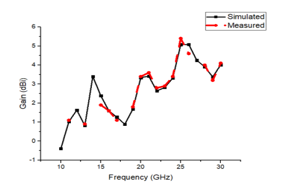
Figure 11 showcases the observed variations in gain as they correlate with the operating frequency. The illustration underscores a pronounced connection between antenna focus and frequency, elucidating that higher frequencies correspond to intensified antenna focus. As a direct outcome of this heightened focus, there is a concurrent decrease in gain while radiation efficiency experiences an augmentation. Across all resonating bands, the antenna has consistently exhibited an average gain of 2.5 decibels isotropic (dBi). This gain aspect is visually depicted in Figure 13.
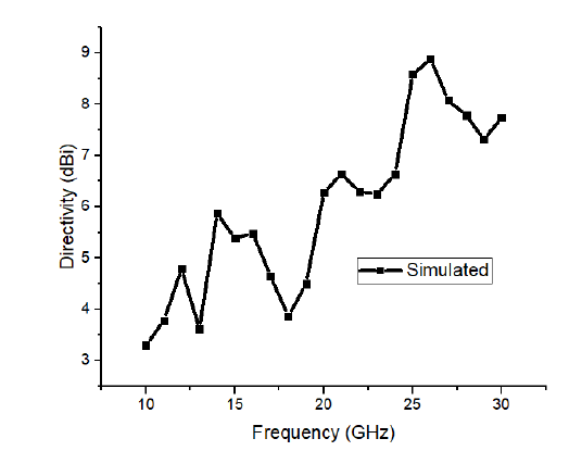
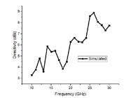
Furthermore, the antenna's directivity is consistently maintained above 4 dBi across all resonating frequencies, as highlighted in Figure 12.


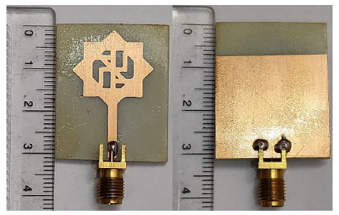
The physical realization of the antenna, achieved through the photolithography method, is visually depicted in Figure 13. The process of photolithography was employed to ensure the successful construction of the antenna. The process begins with the application of a mask containing the inverse of the planned design onto a thoroughly cleaned FR4 substrate treated with acetone. The antenna design employs a dual-sided CU-clad FR4 substrate as its foundational material. Following UV light exposure of the CU-clad FR4, the substrate is immersed in a NaCl developer solution. Subsequently, the etching process utilizing FeCl is executed, concluding with the removal of the photoresist to finalize the fabrication of the intended design.
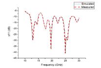
Figure 14 provides a concise visual comparison, juxtaposing the measured and simulated reflection coefficient (S11) against frequency curves for easy assessment. The measured data exhibit a reasonable degree of agreement when contrasted with the simulated data. However, a minor disparity (less than 2 percent) is discernible, particularly concerning operating frequencies and bandwidths. This subtle variation between the measured and simulated outcomes might be attributed, at least in part, to factors such as manufacturing nuances, imprecision in measurement, cable losses, and soldering effects. Table 2 offers a comparative analysis of the proposed antenna against existing literature.
CONCLUSION
This study conducts a comprehensive analysis of a microstrip patch antenna designed for Ku/K band satellite communication services, emphasizing its multiband functionality, including construction, fabrication, and empirical validation against simulated data. The experimental outcomes of the compactly sized antenna indicate bandwidths for a reflection coefficient (S11) of -10 dB spanning 3.02 GHz (11.83 to 14.93 GHz), 4.29 GHz (16.42 to 20.72 GHz), 1.85 GHz (21.38 to 23.40 GHz), and 3.49 GHz (23.74 to 27.09 GHz). The primary resonance frequencies are identified at 12.78, 17.64, 19.71, 22.28, and 25.01 GHz. The antenna exhibits favorable reflection coefficients across the designated frequency ranges and demonstrates commendable gain characteristics, leading to appropriate directional radiation patterns. A comparative analysis between the measured and simulated results highlights a noticeable degree of alignment between the two sets of data. These attributes collectively establish the proposed antenna as well-suited for applications within the Ku/K/Ka band satellite communication realm.
REFERENCES
-
1 Mandal K, Sarkar PP. A compact high gain microstrip antenna for wireless applications. AEU Int J Electron Commun. 2013;67(12):1010-4. doi:10.1016/j.aeue.2013.06.001.
» https://doi.org/10.1016/j.aeue.2013.06.001. -
2 Gupta SK, Sharma M, Kanaujia BK, Gupta A, Pandey GP. Triple band annular ring loaded stacked circular patch microstrip antenna. Wireless Pers Commun. 2014;77(1):633-47. doi:10.1007/s11277-013-1526-9.
» https://doi.org/10.1007/s11277-013-1526-9. - 3 Ullah MH, Islam MT, Mandeep JS. Printed prototype of a wideband S-shape microstrip patch antenna for Ku/K band applications. Appl Comput Electromagn Soc J. 2013;28(4):307-13.
-
4 Roja G, Maheswara Venkatesh P, Jayasankar T. Split Ring Resonator Inspired Dual-Band Monopole Antenna for ISM, WLAN, WIFI, and WiMAX Application. Tech Gaz. 2023;30(5):1533-8. doi:10.17559/TV-20230210000344.
» https://doi.org/10.17559/TV-20230210000344. -
5 Xu P, Yan ZH, Wang C. Multi-band modified fork-shaped monopole antenna with dual L-shaped parasitic plane. Electron Lett. 2011;47(6):364-5. doi:10.1049/el.2010.3280.
» https://doi.org/10.1049/el.2010.3280. -
6 Lee KF, Guo YX, Hawkins JA, Chair R, Luk KM. Theory and experiment on microstrip patch antennas with shorting walls. IEE Proc Microw Antennas Propag. 2000;147(6):521-5. doi:10.1049/ip-map:20000793.
» https://doi.org/10.1049/ip-map:20000793. -
7 Orhan A, Mesud K. The Effect of the Co-Planar Structure on HPBW and the Directional Gain at the Square Patch Antenna around ISM 2450 MHz. Tech Gaz. 2022;29(4):1120-5. doi:10.17559/TV-20190423010908.
» https://doi.org/10.17559/TV-20190423010908. - 8 Ma XL, Shao W, He GQ. A novel dual narrow band-notched CPW-fed UWB slot antenna with parasitic strips. Appl Comput Electromagn Soc J. 2012;27(7):581-6.
-
9 Armagan O, Kahriman M. The Effect of the Co-Planar Structure on HPBW and the Directional Gain at the Square Patch Antenna around ISM 2450 MHz. Tech Gaz. 2022;29(4):1120-5. https://doi.org/10.17559/TV-20190423010908
» https://doi.org/10.17559/TV-20190423010908 -
10 Emadian SR, Ghobadi C, Nourinia J, Mirmozafari M, Pourahmadazar J. Bandwidth enhancement of CPW-fed circle-like slot antenna with dual band-notched characteristic. IEEE Antennas Wireless Propag Lett. 2012;11:543-6. doi:10.1109/LAWP.2012.2199274.
» https://doi.org/10.1109/LAWP.2012.2199274. -
11 Sattar H, Saman E, Rashad M, Mowfaq A. Design and Simulation of Microstrip Antenna Array Operating at S-band for Wireless Communication System. Int J ElectrComput Eng Syst. 2023;14(5):497-506. doi:10.32985/ijeces.14.5.1.
» https://doi.org/10.32985/ijeces.14.5.1. -
12 Bethala C, Kamsali M. Multiband Circularly Polarized Apex Etched Hybrid Rectangular Dielectric Resonator for Wireless Applications. Tech Gaz. 2024;31(3):900-5. https://doi.org/10.17559/TV-20230911000930
» https://doi.org/10.17559/TV-20230911000930 -
13 Liu WC, Wu CM, Dai Y. Design of triple-frequency microstrip-fed monopole antenna using defected ground structure. IEEE Trans Antennas Propag. 2011;59(7):2457-63. doi:10.1109/TAP.2011.2152315.
» https://doi.org/10.1109/TAP.2011.2152315 -
14 Sikkanan S, Srinivasan B, Ganapathy J, Bethala C. Apex Feed Microstrip Printed Hybrid Dielectric Resonator Antenna for Wireless Application. Tech Gaz. 2024;31(3):864-9. https://doi.org/10.17559/TV-20230908000924
» https://doi.org/10.17559/TV-20230908000924 -
15 Islam MT, Cho M, Samsuzzaman M, Kibria S. Compact antenna for small satellite applications. IEEE Antennas Propag Mag. 2015;57(2):30-6. doi:10.1109/MAP.2015.2420471.
» https://doi.org/10.1109/MAP.2015.2420471. -
16 Arnieri E, Boccia L, Amendola G, Di Massa G. A compact high gain antenna for small satellite applications. IEEE Trans Antennas Propag. 2007;55(2):277-82. doi:10.1109/TAP.2006.889831.
» https://doi.org/10.1109/TAP.2006.889831. -
17 Moustafa L, Jecko B. Design of a wideband highly directive EBG antenna using double-layer frequency selective surfaces and multifeed technique for application in the Ku-band. IEEE Antennas Wireless Propag Lett. 2010;9:342-6. doi:10.1109/LAWP.2010.2047630.
» https://doi.org/10.1109/LAWP.2010.2047630. - 18 Samsuzzaman M, Islam MT, Yatim B, Ali MM. Dual frequency triangular slotted microstrip patch antenna for Ku band applications. PrzeglElektrotechn. 2013;89:275-9.
-
19 Prasad Jones Christydass S, Suresh Kumar S, Nishok VS, Saravanakumar R, Devakirubakaran S, Deepa J, Sangeetha K. Design of Metamaterial Antenna Based on the Mathematical Formulation of Patch Antenna for Wireless Application. Int J Antennas Propag. 2023;12 pages. doi:10.1155/2023/2543923.
» https://doi.org/10.1155/2023/2543923. -
20 Mohammad MI, Mohammad TI, Mohammad RIF. Design of Microstrip Antenna OnDuroid 5870 Substrate Material For Ku And K-Band Applications. Tech Gaz. 2015;22(1):71-7. doi:10.17559/TV-20130526131210.
» https://doi.org/10.17559/TV-20130526131210. -
21 Sam PJC, Gunavathi N. A tri-band monopole antenna loaded with circular electric-inductive-capacitive metamaterial resonator for wireless application. Appl Phys. 2020;126(10). doi:10.1007/s00339-020-03952-1.
» https://doi.org/10.1007/s00339-020-03952-1. -
22 Ashwini Kumar A, Seong JK, Sanghoek K. A Dual-Band Antenna for LTE-R and 5G Lower Frequency Operations. Prog Electromagn Res Lett. 2020;88:113-9. doi:10.2528/PIERL19081502.
» https://doi.org/10.2528/PIERL19081502. -
23 Lakshmi MLSNS, Sam S, Kannadhasan PJC, Anguraj S, Jyotir Moy C. Polarization Stable Triband Thin Square-Shaped Metamaterial Absorber. Int J Antennas Propag. 2023. doi:10.1155/2023/6065300.
» https://doi.org/10.1155/2023/6065300. -
24 Boopathi Rani R, Pandey S. A CPW-fed circular patch antenna inspired by reduced ground plane and CSRR slot for UWB applications with notch band. MicrowOpt Technol Lett. 2017;59:745-9. doi:10.1002/mop.30386.
» https://doi.org/10.1002/mop.30386.